Article

Fabrication of UV-Stable Perovskite Solar Cells with Compact Fe2O3 Electron Transport Layer by FeCl3 Solution and Fe3O4 Nanoparticles

1
School of Physics, Southeast University, Nanjing 211189, China
2
School of Materials Science and Engineering, Suzhou University of Science and Technology, Suzhou 215009, China
*
Authors to whom correspondence should be addressed.
These authors contributed equally to this work.
Nanomaterials 2022, 12(24), 4415; https://0-doi-org.brum.beds.ac.uk/10.3390/nano12244415
Submission received: 7 November 2022 / Revised: 8 December 2022 / Accepted: 8 December 2022 / Published: 10 December 2022
(This article belongs to the Special Issue Nanostructured Materials for Energy Applications)

Abstract

:
Even though Fe2O3 is reported as the electron-transporting layer (ETL) in perovskite solar cells (PSCs), its fabrication and defects limit its performance. Herein, we report a Fe2O3 ETL prepared from FeCl3 solution with a dopant Fe3O4 nanoparticle modification. It is found that the mixed solution can reduce the defects and enhance the performance of Fe2O3 ETL, contributing to improved electron transfer and suppressed charge recombination. Consequently, the best efficiency is improved by more than 118% for the optimized device. The stability efficiency of the Fe2O3-ETL-based device is nearly 200% higher than that of the TiO2-ETL-based device after 7 days measurement under a 300 W Xe lamp. This work provides a facile method to fabricate environmentally friendly, high-quality Fe2O3 ETL for perovskite photovoltaic devices and provides a guide for defect passivation research.

1. Introduction

Organic–inorganic hybrid lead halide perovskites have attracted extensive attention [1,2]. Since the first reports in 2009, the power conversion efficiency (PCE) of PSCs has been improved to 25.7% within about one decade [3,4,5]. A typical planar PSC is composed of the structure of a cathode layer [6]. The ETL plays a significant role in electron extraction and transport from the perovskite absorber to the FTO [7]. To obtain highly efficient perovskite solar cells, a thin, transparent, and electrically conductive ETL without pinholes is crucial.
Currently, the most commonly used ETL material in PSCs is TiO2, owing to its high chemical stability, innate transparency, inexpensiveness, and appropriate conduction band (CB) level aligning with the perovskite layer [8]. However, TiO2-based devices are reported to suffer from hysteresis and high charge recombination, which severely restricts the wide use of the TiO2 ETL and hinders the development of PSCs [9]. Moreover, the photocatalytic properties of TiO2 could reduce the illumination stability of PSCs, resulting in poor UV light stability in PSCs [10]. Thus, a great deal of effort has been made to alleviate this problem. Meanwhile, many endeavors have been directed at searching for alternative semiconductor materials for ETLs, such as SnO2, ZnO, and Nb2O5 [11].
As an n-type semiconductor, iron oxide (Fe2O3) has attracted increased attention in photovoltaic applications, due to its high chemical stability, low cost, and suitable energy band position [12]. Considering its ultraviolet stability and visible light absorption, Fe2O3 is one of the most promising candidates for the ETL in PSCs. However, only several studies have been reported on the application of Fe2O3 in PSCs [13,14,15,16]. Wang et al. applied spin-coated Fe2O3 as the ETL in PSCs, attaining a PCE of 10.7%, with stability over 30 days upon exposure to ambient air, indicating high stability but a poor efficiency [14]. Guo et al. reported the application of Ni-doped Fe2O3 ETL, achieving an efficiency of 14.2%. They also reported the application of γ-Fe2O3 ETL fabricated at room temperature. However, it is difficult to fabricate Fe2O3 films with good conductivity and crystallinity [15,16].
Herein, we report an Fe2O3 ETL fabricated with the water-dispersed Fe3O4 nanoparticles and FeCl3 solution. It is found that the addition of FeCl3 in Fe3O4 nanoparticles precursor reduces the defects and enhances the passivation ability. As a result, the improved electron transfer and suppressed charge recombination contribute to an improvement in the short circuit current density (Jsc) and open-circuit voltages (Voc), eventually yielding a champion PCE of 12.61%.

2. Experimental Section

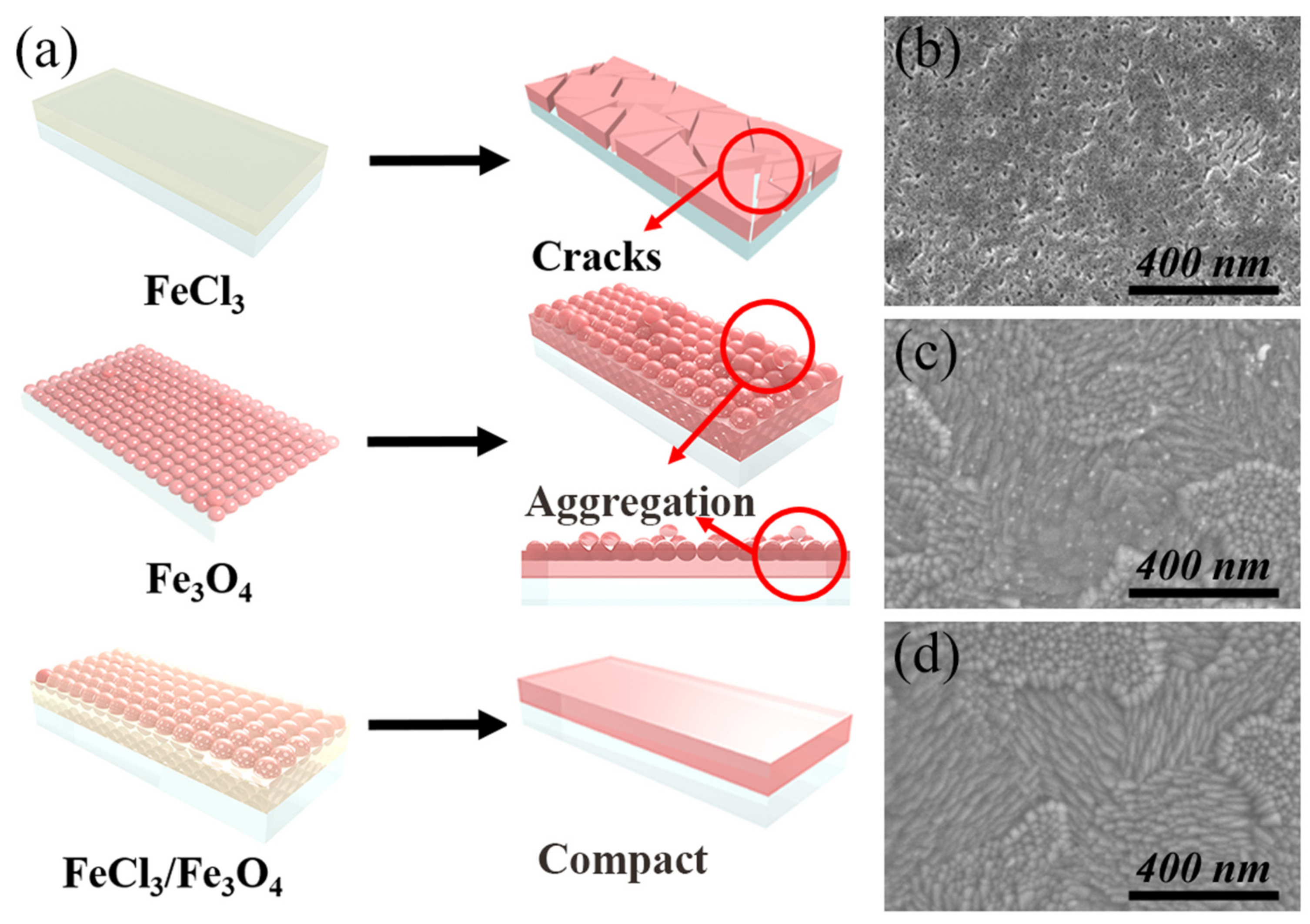
2.1. Preparation of Fe2O3 ETLs

The ITO substrates were rinsed by ultrasonic vibration with acetone, ethanol, and deionized water for 30 min, and then treated with UV–ozone irradiation for 15 min.
A total of 600 mg of 2.2 mM FeCl3·6H2O (Alfa Aesar, 97%) and 300 mg of 1.5 mM FeCl2·4H2O (Alfa Aesar, 99%) was dissolved in 5 mL deionized water. Next, 800 mg of polyglucose sorbitol carboxymethylether was dissolved in 10 mL deionized water. Then, both of the solutions were mixed in a three-neck bottle, and stirred vigorously (300 rpm) with nitrogen gas bubbling. Then, the bottle was immediately transferred to a water bath at 60 °C, and 900 μL of 28% ammonium aqueous solution was added (stirring at 800 rpm). The bottle was transferred to a cryogenic bath (containing cold water, ice water, and ethanol). After cooling to −5 °C (decline rate 0.28 °C min−1), Fe3O4 nanoparticles solution was eventually obtained after workup by dialysis and filtration.
The Fe2O3 films fabricated with Fe3O4 nanoparticles were deposited on the substrates by spin-coating water-dispersed ten-nm-sized Fe3O4 nanoparticles with a concentration of 0.075 M at 5000 rpm for 30 s. The as-prepared layers were then annealed at 550 °C for 120 min in air. For the Fe2O3 films fabricated with FeCl3 solution, the precursor solution was prepared by dissolving FeCl3·6H2O (Alfa Aesar, 97%) in deionized water with a concentration of 0.075 M. The Fe2O3 films were deposited by spin-coating the prepared precursor solution at 4000 rpm for 30 s and sintered at 550 °C for 120 min in air. For the Fe2O3 films fabricated with FeCl3/Fe3O4 mixed solution, the mixed solution was prepared by dissolving FeCl3·6H2O in the as-prepared Fe3O4 solution with a concentration of 0.075 M. The Fe2O3 films were fabricated by spin-coating the mixed solution at 5000 rpm for 30 s, and then annealed at 550 °C for 120 min in air.

2.2. Fabrication of Perovskite Solar Cells

Perovskite solar cells were fabricated by a modified two-step method. Firstly, a PbI2 solution with 600 mg mL−1 in DMF was dropped on the ETL substrate with 3000 rpm for 30 s. A total of 50 µL of mixed solution (60 mg mL−1 FAI, 6 mg mL−1, MABr, and 6 mg mL−1 MACl in isopropanol) was then rapidly dripped on the rotating substrate 10 s after the spin procedure started. The as-prepared film was heated at 150 °C for 10 min in air in order to obtain a dense perovskite film. After cooling to room temperature, the HTL solution (spiro-OMeTAD, 25 µL) was deposited by spin-coating at 2000 rpm for 30 s. The HTL solution consisted of 72.3 mg spiro-OMeTAD, 28.8 µL 4-tert-butylpyridine (TBP), and 17.5 µL of 520 mg mL−1 lithium bis(trifluoromethylsulphonyl)imide (LiTFSI) in acetonitrile dissolved in 1 mL of chlorobenzene. Then, devices were oxidized in air for 36 h.

2.3. Characterization and Measurement

The surface morphology and cross-section of the samples were observed by a field-emission scanning electron microscope (FE-SEM, Hitachi, SU8010, Japan). The XRD results were measured with an X-ray diffractometer (XRD, Bruker, D8 Advance, Germany). The samples were also investigated by X-ray photoelectron spectroscopy (Thermo, Escalab 250Xi, USA). The photoluminescence (PL) and time-resolved photoluminescence (TRPL) were detected with a 530 nm laser (Edinburgh Instruments, LP320, UK). The absorption spectra were recorded on a UV–vis spectrophotometer (Shimadzu, UV-2600, Japan). The contact angle measurement was measured by DSA25E (KRÜSS, Germany). The current–voltage characteristics of the solar cells were tested with a Newport solar simulator and a Keithley 2400 Source Meter under AM 1.5G irradiation (100 mW cm−2). The electrochemical impedance spectroscopy (EIS) was measured with an electrochemical workstation (Autolab, PGSTAT 302 N, Switzerland) under AM 1.5G light condition with an alternative signal amplitude of 10 mV and in the frequency range of 0.1 Hz-40 kHz in glove box.

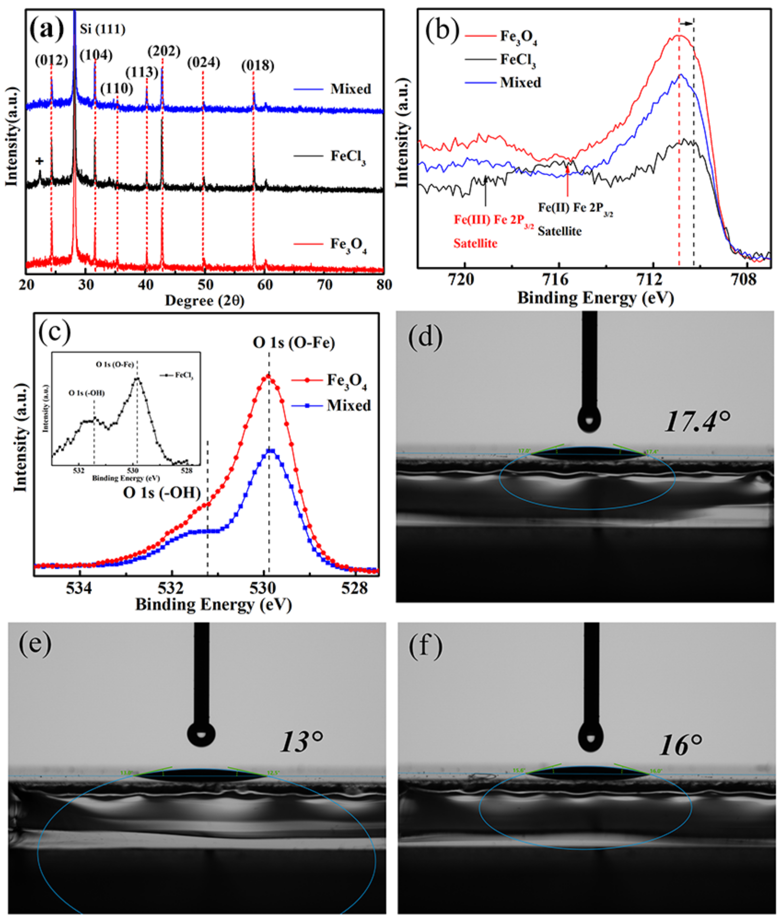
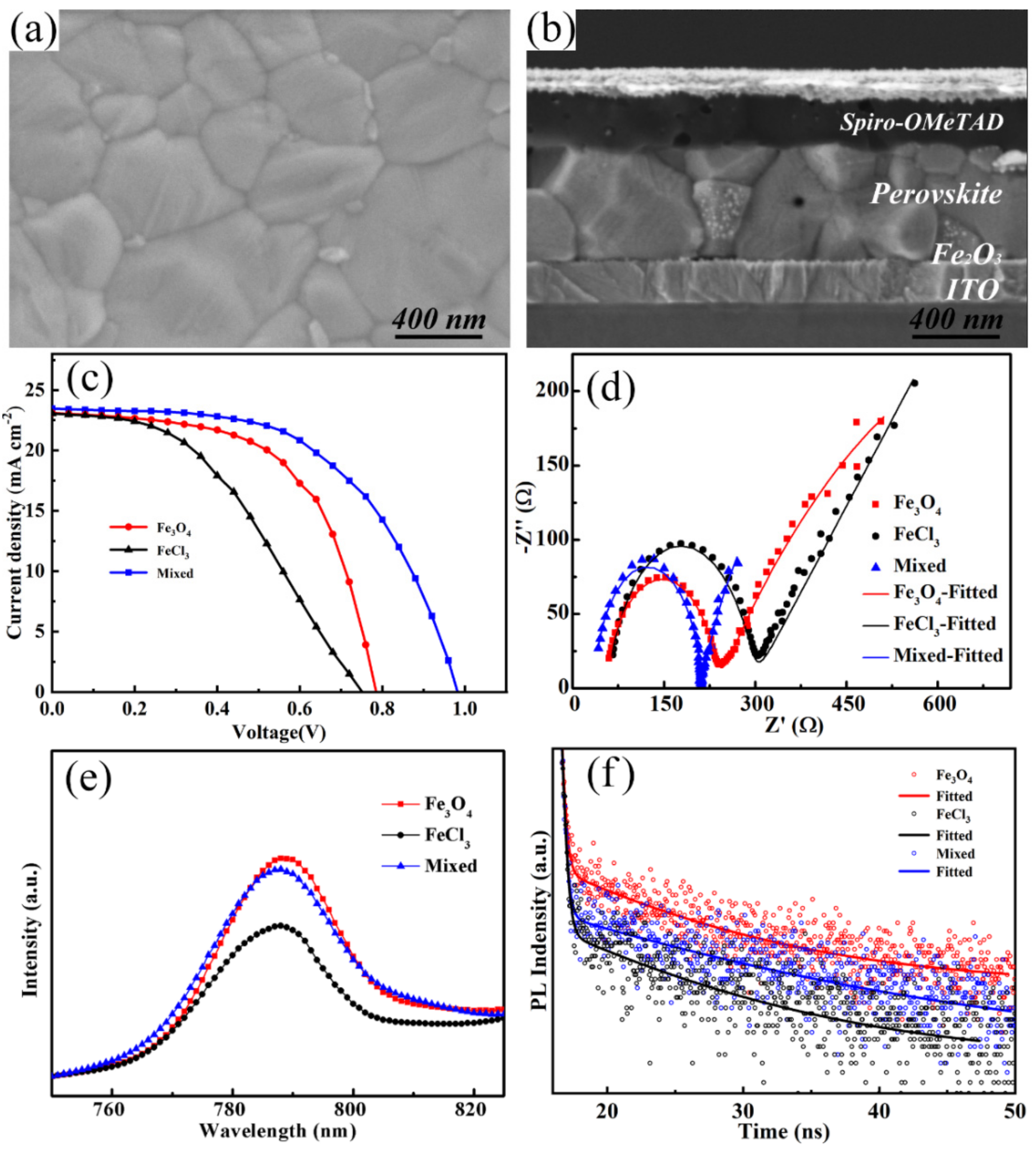
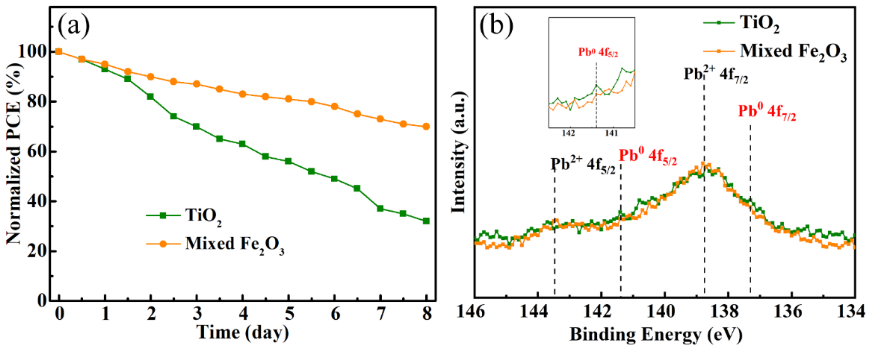
3. Results and Discussion

Figure 1a exhibits the schematic of different Fe2O3 films prepared by FeCl3 solution, Fe3O4 nanoparticles, and FeCl3/Fe3O4 mixed solution. Fe2O3 films prepared by FeCl3 solution exhibit good compactness, but a large number of cracks and pin-holes after the annealing process. Fe2O3 films fabricated by water-dispersed Fe3O4 nanoparticles show better morphology. However, some aggregation is still found, owing to the gathered nanoparticles in the crystallization process, which could influence the nucleation process of perovskite film and suppress the charge transport at the Fe2O3/perovskite interface.
In order to further improve the planarity and compactness of Fe2O3 films, FeCl3 solution was incorporated into the Fe3O4 nanoparticle precursor solution, which could simultaneously retain the advantages of the two methods and reduce the defects, thereby facilitating an efficient ETL. Figure S1 shows the top-view scanning electron microscopy (SEM) image of blank and clean ITO substrate, as previously reported. As shown in Figure 1b, the Fe2O3 film prepared by 0.075 M FeCl3 solution shows a morphology with cracks and pin-holes, which could lead to direct contact between the perovskite absorber and ITO, resulting in aggravated charge recombination. Figure 1c shows the morphology of the Fe2O3 film fabricated by spin-coating water-dispersed ten-nm-sized Fe3O4 nanoparticles with a concentration of 6 mg mL−1 (measured by Fe), which demonstrates a flat and compact surface except for a few gathered spots. Figure 1d depicts the morphology of the Fe2O3 film prepared by FeCl3/Fe3O4 mixed solution. It can be observed that the as-prepared Fe2O3 film exhibits a pin-hole-free coverage, as a result of the cooperation between the nanoparticles and FeCl3 solution in the annealing process.
Figure 2a shows the X-ray diffraction (XRD) pattern of the Fe2O3 films prepared by different methods. XRD analysis confirms that both the samples prepared by Fe3O4 nanoparticles and FeCl3/Fe3O4 mixed solution display the same diffraction peaks, which match the standard α-Fe2O3 perfectly (JCPDS, No. 80-2377) [17]. XRD peaks at 22.5 and 24 degree may be the peaks of iron chlorate formed by the incompletely volatilized Cl in the crystallization process and the reduced iron. While the sample prepared by FeCl3 solution displays an extra peak at low angle. The XRD results indicate that Fe3O4 is converted into Fe2O3 and that the FeCl3/Fe3O4 mixed sample has better purity. X-ray photoelectron spectroscopy (XPS) measurements were carried out to elucidate the chemical composition of Fe2O3 films prepared by different methods.
Figure 2b illustrates the Fe 2p3/2 peak of the as-prepared Fe2O3 films. The fitted curves are shown in Figure S2. The peaks center around 716 eV and 719 eV, corresponding to the binding energy of Fe2+ ions and Fe3+ ions, respectively [18]. The curves of the samples prepared by Fe3O4 nanoparticles and FeCl3/Fe3O4 mixed solution show no obvious peak of Fe2+ ions, indicating that the Fe elements are converted into Fe2O3.
As shown in Figure 2c, a little peak of O-H can be observed in samples prepared by mixed solution, proving that there are intermediate products during the annealing process. To ascertain the influence of the different preparation methods on the surface energy, a contact angle test was carried out on the as-prepared Fe2O3 substrates. The contact angles are 13°, 17.4°, and 16° for Fe2O3 films prepared by FeCl3 solution, Fe3O4 nanoparticles, and FeCl3/Fe3O4 mixed solution, respectively. For the FeCl3 prepared sample, the smallest contact angle could arise from its terrible morphology with large-area cracks and pin-holes, which could trap the perovskite precursor solution. It should be noted that the FeCl3/Fe3O4 mixed sample has a smaller contact angle than that of Fe3O4 nanoparticles. Attributing this to the addition of FeCl3 solution, the defects and aggregation of the Fe3O4 prepared films are passivated, leading to a compact and flat coverage of the Fe2O3 film prepared by FeCl3/Fe3O4 mixed solution. The reduced defects and passivated surface of the Fe2O3 films make a great contribution to a smaller contact angle, which is conducive to the diffusion of perovskite precursor solution on the surface, thus, accelerating the nucleation process of perovskite films [19]. Figure S3 illustrates the UV–vis absorption spectra of Fe2O3 films prepared by different methods. The Fe2O3 film prepared by FeCl3/Fe3O4 mixed solution shows a slightly higher absorption in almost the whole wavelength region, which could prevent the perovskite from degrading under UV irradiation and enhance the UV-stable ability.
Figure 3a shows the top-view SEM image of the perovskite layer deposited on the FeCl3/Fe3O4 mixed sample, which exhibits compact surface and large grain size. Figure 3b shows the cross-sectional SEM image of the entire structure, from which we can see the perovskite layer is also compact and the thickness is about 500 nm. Figure S4 shows the XRD patterns of perovskite coated on as-prepared substrates, and all the peaks of the perovskite are presented with an asterisk. All of them display the same characteristic peaks of perovskite materials, which indicates excellent perovskite crystallinity [20]. Figure 3c presents the best current density–voltage (J-V) curves of the devices based on Fe2O3 films prepared by different methods. All samples were measured under AM 1.5G (from 1.2 V to 0 V, scan step of 0.04 V, and scan rate of 100 mV s−1). The devices based on Fe2O3 films are also compared with the TiO2-based device, as shown in Figure S5. The detailed photovoltaic parameters of the PSCs with the best PCE values including open-circuit voltage (Voc), short-circuit current density (JSC), filling factor (FF), and PCE are summarized in Table S1. The device prepared with FeCl3 displays the lowest PCE of 7.72% and the device based on Fe3O4 nanoparticles provides a PCE of 10.64%. Expectedly, the optimal device prepared by mixed solution exhibits overall superior performance, including a Voc of 0.98 V, Jsc of 23.45 mA cm−2, and FF of 54.74%, resulting in a PCE of 12.61%. Compared with the device based on single Fe3O4 nanoparticles, Voc and Jsc are improved, which may be due to the reduced defects and passivated recombination with the addition of FeCl3. The forward and reverse scanning tests were also carried out to investigate the hysteresis effect by (PCEreverse − PCEforward)/PCEreverse. As shown in Figure S6, the mixed sample shows a minimum hysteresis of 0.09. As a contrast, the FeCl3 prepared sample shows a hysteresis index of 0.15, and that of the Fe3O4 prepared sample is 0.10. It is indicated that PSC based on the mixed sample shows a better charge-transfer ability. Further characterizations were performed to evaluate the trap state density of the devices. We prepared electron-only devices with structures of ITO/ETL/perovskite/PCBM/Ag to quantitatively assess the trap state density in ETL, as shown in Figure S7. Compared with the Fe3O4-based device, the VTFL of the mixed sample is reduced to 0.12 V. It is indicated that that addition of FeCl3 can obtain high-quality Fe2O3 film with compact and flat coverage, contributing to passivating the surface defect and effectively filling the electron trap density, which can greatly improve the electrical properties and accelerate electron extraction and injection at the ETL/perovskite interface.
To investigate charge transport and recombination in perovskite solar cells, electrochemical impedance spectroscopy (EIS) was conducted. Figure 3d shows the Nyquist plots of the devices based on Fe3O3 ETLs prepared by different methods under AM 1.5 G illumination, and the fitted parameters are summarized in Table S2. The semicircle at high frequency is related to the transfer resistance (Rct) at the interface and the semicircle at low frequency corresponds to recombination impedance (Rrec) of the device [21]. The device based on FeCl3/Fe3O4 film exhibits a Rct of 178 Ω and Rrec of 1023 Ω. The reduced Rct is conducive to the enhanced the carriers transfer at the interface, and the increased Rrec is beneficial to the suppressed charge recombination. To further investigate the leakage capacity of Fe3O3 ETLs prepared by different methods, a leakage current test is carried out, as shown in Figure S8. The FeCl3/Fe3O4-based sample shows the lowest leakage value, indicating a better leakage performance.
Photoluminescence (PL) was carried out to explore the carrier transport dynamics at the Fe2O3/perovskite interface, as shown in Figure 3e. All the samples display a typical emission peak at 788 nm, in agreement with the absorbance edge of the perovskite. The FeCl3 prepared sample presents the lowest PL intensity. This could mainly be correlated to poor coverage of the prepared film, which could cause the direct contact between perovskite and ITO, resulting in an illusion of great electron transfer and extraction. A higher PL intensity is presented in the sample with Fe3O4-prepared films. It should be ascribed to the imperfect surface and interface. The FeCl3/Fe3O4-prepared film demonstrates a PL quenching, indicating that the addition of FeCl3 can passivate the surface defect and accelerate electron extraction and injection at the ETL/perovskite interface. To further demonstrate the charge transfer and extraction, the time-resolved photoluminescence (TRPL) was performed. Figure 3f shows the TRPL spectra and the fitting curves with a bi-exponential decay function [22]. It is clear that the average recombination lifetime (τave) is prolonged from 7.76 ns to 20.28, and 12.29 ns for samples with FeCl3, Fe3O4, and FeCl3/Fe3O4-prepared films, respectively. Compared to the Fe3O4- prepared sample, the decreased carrier lifetime of the FeCl3/Fe3O4-prepared sample indicates that the addition of FeCl3 passivates defects of the Fe3O4 prepared films and greatly accelerates the charge separation and transport, leading to suppressed charge recombination.
The transmittance spectra of Fe2O3 films prepared by different methods are shown in Figure S9. The FeCl3/Fe3O4-prepared film shows a high transmission, but it is still slightly lower than that of the TiO2 film. Figure 4a shows the long-time stability test of controlled TiO2 and mixed Fe2O3-ETL-based perovskite solar cell, which were tested under a 300 W Xe lamp with the condition of humidity of less than 20% and temperature of 25 ℃. In order to obtain more accurate stability test results, we used Au as the top electrode instead of the original Ag. The efficiency of the device prepared by controlled TiO2 ETL decreases more than 70% after 7 days of continuous irradiation. As the most commonly used ETL material in PSCs, TiO2 is reported as a serious issue that affects the stability of the PSCs. As a product of the TiO2 photocatalytic effect, UV illumination can excite TiO2 to generate strong oxidizing holes, which could cause the decomposition of perovskite into CH3NH2, HI, and PbI2, and eventually result in the degradation of the stability [23,24,25]. The device prepared with mixed Fe2O3 ETL still has 70% efficiency, indicating a better stability performance. We speculate that it is due to the UV stability and lesser photocatalytic ability of Fe2O3, which slows the perovskite from degradation and, thus, enhances the UV-stable ability of PSCs. We also tested the TiO2 and mixed-Fe2O3-based devices at the maximum power point (MPP) to investigate the stability under UV illumination (composed of 313 nm, 340 nm, and 351 nm) without encapsulation, as shown in Figure S10. Under the same conditions for 300 min, the mixed-Fe2O3-based device retains 86% of its initial current density, while the current density of the TiO2-based device only retains 52%, indicating no UV reaction of Fe2O3 and perovskite, which makes a great contribution to the UV-stable devices. To further confirm our point of view, the XPS measurements were carried out to elucidate the valance change of Pb in the perovskite of controlled TiO2 and mixed-Fe2O3-ETL-based perovskite solar cells, which were tested for long-time stability for 7 days. Figure 4b shows the peak of the XPS spectra centered at 141.4 eV, corresponding to Pb0 4f5/2 of controlled TiO2-based sample, which is in good agreement with the literature values of 141.7 eV [26]. The peak is higher than that of the Fe2O3-based sample, confirming the presence of unsaturated Pb, which results from the degradation of perovskite and could be detrimental to the instability of the sample. For the Fe2O3-based sample, the peak of Pb0 4f5/2 is successfully suppressed, indicating improved stability of the perovskite. We think that the improvement of the stability should be ascribed to no UV reaction of Fe2O3, which protects perovskite from degradation under continuous irradiation.

4. Conclusions

In summary, we present a facile modification with FeCl3 solution to optimize the Fe2O3 ETL prepared by water-dispersed Fe3O4 nanoparticles. The device efficiency is improved by more than 118% for the optimized device. The stability efficiency of the Fe2O3-ETL-based device is nearly 200% higher than that of the TiO2-ETL-based device after 7 days measurement. The improved performance of the as-prepared solar cells is attributed to the reduced defects at the interface, enhanced passivation ability, excellent perovskite crystallization originating from the addition of the FeCl3, and the UV-stable ability of the Fe2O3-based devices. This work is dedicated to broadening the scope of perovskite photovoltaic devices and provides a way for defect passivation in commercial applications.

Supplementary Materials

The following supporting information can be downloaded at: https://0-www-mdpi-com.brum.beds.ac.uk/article/10.3390/nano12244415/s1, Figure S1. Top-view SEM images of pure ITO; Figure S2. Fitted curves of the Fe 2P3/2 of Fe2O3 films prepared by different methods; Figure S3. UV–vis absorption spectra of Fe2O3 films prepared by different methods; Figure S4. XRD patterns of perovskite coated on different substrates; Figure S5. J-V curves of PSCs based on Fe2O3 and TiO2 ETLs; Figure S6. Hysteresis measurement of PSCs based on Fe2O3 prepared by different methods; Figure S7. Current−voltage curves of the PSCs with a structure of ITO/HTMs/perovskite/spiro-OMeTAD/Ag; Figure S8. Leakage current measurement of PSCs based on the Fe2O3 ETLs prepared by different methods; Figure S9. Transmittance spectra of TiO2 and Fe2O3 films prepared by different methods. Figure S10. The continuous illumination stability of the TiO2 and mixed Fe2O3 based devices under UV illumination without encapsulation; Table S1. Summary of photovoltaic parameters of the PSCs based on the control TiO2 ETLs and Fe2O3 ETLs prepared by different methods (30 devices tested in the reversed direction); Table S2. Summary of the fitted parameters of solar cells based on the Fe2O3 ETLs prepared by different methods.

Author Contributions

Data curation, B.G., Y.D., X.C., X.L. and H.L.; funding acquisition, Q.X. and H.L.; methodology, Y.D., S.F. and H.L.; Writing—original draft, B.G.; Writing—review and editing, H.L. All authors have read and agreed to the published version of the manuscript.

Funding

We acknowledge the support from the National Natural Science Foundation of China (51802210), Excellent Youth Foundation of Jiangsu Science Committee (BK20220118), Natural Science Foundation of the Jiangsu Higher Education Institutions of China (22KJD430009), The Fundamental Research Funds for the Central Universities (2242020k30039), and the open research fund of the Key Laboratory of MEMS of Ministry of Education, Southeast University.

Institutional Review Board Statement

Not applicable.

Informed Consent Statement

Not applicable.

Data Availability Statement

The data is available on reasonable request from the corresponding author.

Conflicts of Interest

The authors declare no conflict of interest.

References

  1. Kong, J.; Shin, Y.; Röhr, J.A.; Wang, H.; Meng, J.; Wu, Y.; Katzenberg, A.; Kim, G.; Kim, D.Y.; Li, T.-D.; et al. CO2 Doping of Organic Interlayers for Perovskite Solar Cells. Nature 2021, 594, 51–56. [Google Scholar] [CrossRef] [PubMed]
  2. Choi, D.-S.; Kwon, S.-N.; Na, S.-I. Non-Fullerene Small Molecule Electron-Transporting Materials for Efficient p-i-n Perovskite Solar Cells. Nanomaterials 2020, 10, 1082. [Google Scholar] [CrossRef] [PubMed]
  3. Kojima, A.; Teshima, K.; Shirai, Y.; Miyasaka, T. Organometal Halide Perovskites as Visible-Light Sensitizers for Photovoltaic Cells. J. Am. Chem. Soc. 2009, 131, 6050–6051. [Google Scholar] [CrossRef] [PubMed]
  4. Lu, H.; Zhong, J.; Ji, C.; Zhao, J.; Li, D.; Zhao, R.; Jiang, Y.; Fang, S.; Liang, T.; Li, H.; et al. Fabricating an Optimal Rutile TiO2 Electron Transport Layer by delicately tuning TiCl4 precursor solution for High Performance Perovskite Solar Cells. Nano Energy 2020, 68, 104336. [Google Scholar] [CrossRef]
  5. NREL. Available online: https://www.nrel.gov/pv/cell-efficiency.html (accessed on 30 June 2022).
  6. Yang, X.; Luo, D.; Xiang, Y.; Zhao, L.; Anaya, M.; Shen, Y.; Wu, J.; Yang, W.; Chiang, Y.-H.; Tu, Y.; et al. Buried Interfaces in Halide Perovskite Photovoltaics. Adv. Mater. 2021, 33, 2006435. [Google Scholar] [CrossRef] [PubMed]
  7. Xiong, S.; Dai, Y.; Yang, J.; Xiao, W.; Li, D.; Liu, X.; Ding, L.; Gao, P.; Fahlman, M.; Bao, Q. Surface Charge-Transfer Doping for Highly Efficient Perovskite Solar Cells. Nano Energy 2021, 79, 105505. [Google Scholar] [CrossRef]
  8. Yin, R.; Wang, K.-X.; Huo, X.-N.; Sun, Y.-S.; Sun, W.-W.; Gao, Y.-K.; You, T.-T.; Yin, P.-G. A One-Step Ionic Liquid Interface-to-Bulk Modification for Stable Carbon-Based CsPbI3 Perovskite Solar Cells with Efficiency Over 15%. Adv. Mater. Interfaces 2022, 9, 2201488. [Google Scholar] [CrossRef]
  9. Wu, T.; Zhao, R.; Qiu, J.; Wang, S.; Zhang, X.; Hua, Y. Enhancing the Hot Carrier Injection of Perovskite Solar Cells by Incorporating a Molecular Dipole Interlayer. Adv. Funct. Mater. 2022, 32, 2204450. [Google Scholar] [CrossRef]
  10. Wang, B.; Yang, J.; Lu, L.; Xiao, W.; Wu, H.; Xiong, S.; Tang, J.; Duan, C.; Bao, B. Interface Engineering of Air-Stable n-Doping Fullerene-Modified TiO2 Electron Transport Layer for Highly Efficient and Stable Perovskite Solar Cells. Adv. Mater. Interfaces 2020, 7, 1901964. [Google Scholar] [CrossRef]
  11. Liu, Q.; Zhang, X.; Li, C.; Lu, H.; Weng, Z.; Pan, Y.; Chen, W.; Hang, X.-C.; Sun, Z.; Zhan, Y. Effect of Tantalum Doping on SnO2 Electron Transport Layer via Low Temperature Process for Perovskite Solar Cells. Appl. Phys. Lett. 2019, 115, 143903. [Google Scholar] [CrossRef]
  12. Tang, C.; Sun, B.; Li, M.; Zhang, J.; Fan, X.; Gao, F.; Tong, Y.; Dong, L.; Li, Y. Surface Hydroxylated Hematite Promotes Photoinduced Hole Transfer for Water Oxidation. J. Mater. Chem. A 2019, 7, 8050–8054. [Google Scholar] [CrossRef]
  13. Fisher, D.; Rajbhandari, P.-P.; Dhakal, T.-P. Fe2O3 as an Electron Transport Material for Organo-Metal Halide Perovskite Solar Cells. In Proceedings of the IEEE 44th Photovoltaic Specialists Conference (PVSC), Washington, DC, USA, 25–30 June 2017; pp. 989–992. [Google Scholar]
  14. Hu, W.; Liu, T.; Yin, X.; Liu, H.; Zhao, X.; Luo, S.; Guo, Y.; Yao, Z.; Wang, J.; Wang, N.; et al. Hematite Electron-Transporting Layers for Environmentally Stable Planar Perovskite Solar Cells with Enhanced Energy Conversion and Lower Hysteresis. J. Mater. Chem. A 2017, 5, 1434–1441. [Google Scholar] [CrossRef]
  15. Guo, Y.; Liu, T.; Wang, N.; Luo, Q.; Lin, H.; Li, J.; Jiang, Q.; Wu, L.; Guo, Z. Ni-doped α-Fe2O3 as electron transporting material for Planar Heterojunction Perovskite Solar Cells with Improved Efficiency, Reduced Hysteresis and Ultraviolet Stability. Nano Energy 2017, 38, 193–200. [Google Scholar] [CrossRef]
  16. Guo, Y.; He, H. γ-Fe2O3 as a Novel Electron Transporting Material for Planar Heterojunction Perovskite Solar Cells by Simple Room-Temperature Solution Method. Earth Environ. Sci. 2019, 358, 052022. [Google Scholar] [CrossRef] [Green Version]
  17. Li, S.S.; Li, W.-J.; Jiang, T.-J.; Liu, Z.-G.; Chen, X.; Cong, H.-P.; Liu, J.-H.; Huang, Y.-Y.; Li, L.-N.; Huang, X.-J. Iron Oxide with Different Crystal Phases (α- and γ-Fe2O3) in Electroanalysis and Ultrasensitive and Selective Detection of Lead(II): An Advancing Approach Using XPS and EXAFS. Anal. Chem. 2016, 88, 906–914. [Google Scholar] [CrossRef]
  18. Zhou, G.; Yang, X.; Xiao, L.; Sun, B.; Zhou, A. Investigation of a Submerging Redox Behavior in Fe2O3 Solid Electrolyte for Resistive Switching Memory. Appl. Phys. Lett. 2019, 114, 163506. [Google Scholar] [CrossRef]
  19. Wu, G.; Liang, R.; Ge, M.; Sun, G.; Zhang, Y.; Xing, G. Surface Passivation Using 2D Perovskites toward Efficient and Stable Perovskite Solar Cell. Adv. Mater. 2022, 34, 2105635. [Google Scholar] [CrossRef]
  20. Wang, J.; Meng, F.; Li, R.; Chen, S.; Huang, X.; Xu, J.; Lin, X.; Chen, R.; Wu, H.; Wang, H.-L. Boosting Efficiency and Stability of Planar Inverted (FAPbI3)x(MAPbBr3)1−x Solar Cells via FAPbI3 and MAPbBr3 Crystal Powders. Sol. RRL 2020, 4, 2000091. [Google Scholar] [CrossRef]
  21. Gu, B.; Du, Y.; Chen, B.; Zhao, R.; Lu, H.; Xu, Q.; Guo, C. Black Phosphorus Quantum Dot-Engineered Tin Oxide Electron Transport Layer for Highly Stable Perovskite Solar Cells with Negligible Hysteresis. ACS Appl. Mater. Interfaces 2022, 14, 11264–11272. [Google Scholar] [CrossRef]
  22. Luo, T.; Ye, G.; Chen, X.; Wu, H.; Zhang, W.; Chang, H. F-doping-Enhanced Carrier Transport in the SnO2/Perovskite Interface for High-Performance Perovskite Solar Cells. ACS Appl. Mater. Interfaces 2022, 14, 42093–42101. [Google Scholar] [CrossRef]
  23. Niu, G.; Guo, X.; Wang, L. Review of Recent Progress in Chemical Stability of Perovskite Solar Cells. J. Mater. Chem. A. 2015, 3, 8970–8980. [Google Scholar] [CrossRef]
  24. Huang, M.; Zhao, Q.; Chen, Z.; Shou, C.; Shen, Q.; Yang, S. A UV-Stable Perovskite Solar Cell Based on Mo-doped TiO2 Interlayer. Chem. Lett. 2019, 48, 700–703. [Google Scholar] [CrossRef]
  25. Ouafi, M.; Jaber, B.; Atourki, L.; Bekkari, R.; Laânab, L. Improving UV Stability of MAPbI3 Perovskite Thin Films by Bromide Incorporation. J. Alloy. Compd. 2018, 746, 391–398. [Google Scholar] [CrossRef]
  26. Shai, X.; Zuo, L.; Sun, P.; Liao, P.; Huang, W.; Yao, E.-P.; Li, H.; Liu, S.; Shen, Y.; Yang, Y.; et al. Efficient Planar Perovskite Solar Cells using Halide Sr-substituted Pb Perovskite. Nano Energy 2017, 36, 213–222. [Google Scholar] [CrossRef]
Figure 1. (a) Schematic of Fe2O3 films prepared by FeCl3 solution, Fe3O4 nanoparticles, and FeCl3/Fe3O4 mixed solution. Top-view SEM images of Fe2O3 film prepared by (b) 0.075 M FeCl3 solution, (c) water-dispersed ten-nm-sized Fe3O4 nanoparticles, and (d) FeCl3/Fe3O4 mixed solution.
Nanomaterials 12 04415 g001
Figure 2. (a) XRD patterns, XPS spectra of (b) Fe 2P3/2 and (c) O 1s of Fe2O3 films prepared by FeCl3 solution, Fe3O4 nanoparticles, and FeCl3/Fe3O4 mixed solution, contact angle of Fe2O3 films prepared by (d) Fe3O4 nanoparticles, (e) FeCl3 solution, and (f) FeCl3/Fe3O4 mixed solution.
Nanomaterials 12 04415 g002
Figure 3. (a) Top-view SEM image of the perovskite layer. (b) Cross-sectional SEM image of the entire structure. (c) J-V curves of PSCs based on Fe2O3 ETLs prepared by different methods. (d) Nyquist plots of PSCs based on the Fe2O3 ETLs prepared by different methods. (e) PL spectra, (f) TRPL spectra of perovskite based on Fe2O3 films prepared by different methods.
Nanomaterials 12 04415 g003
Figure 4. (a) Long-time stability test under AM 1.5 G of controlled TiO2 and mixed-SnO2-ETL-based perovskite solar cells. (b) XPS spectra depicting Pb 4f5/2 and Pb 4f7/2 peaks of controlled TiO2 and mixed-SnO2-ETL-based perovskite solar cell, which were tested for long-time stability for 7 days.
Nanomaterials 12 04415 g004
Publisher’s Note: MDPI stays neutral with regard to jurisdictional claims in published maps and institutional affiliations.

