Non-Enzymatic Glucose Biosensor Based on Highly Pure TiO2 Nanoparticles
by

Hongin Jeong
1, 
Jhongryul Yoo
1,
Seokyung Park
2,
Jiling Lu
2,
Sungho Park
1,* and
Jeseung Lee
2,* 1
Department of Life Science and Chemistry, Daejin University, 1007 Hoguk Road, Pocheon-si 11159, Korea
2
Department of Chemistry and Research Institute of Basic Sciences, Kyung Hee University, 26 Kyungheedae-ro, Dongdaemun-gu, Seoul 02447, Korea
*
Authors to whom correspondence should be addressed.
Biosensors 2021, 11(5), 149; https://0-doi-org.brum.beds.ac.uk/10.3390/bios11050149
Submission received: 9 April 2021
/
Revised: 29 April 2021
/
Accepted: 7 May 2021
/
Published: 11 May 2021
(This article belongs to the Section Biosensor and Bioelectronic Devices)
Abstract
:This study proposes a non-enzymatic glucose sensor fabricated by synthesizing high-purity TiO2 nanoparticles in thermal plasma and depositing it directly on a substrate and then depositing chitosan–polypyrrole (CS-PPy) conductive polymer films by electrochemical method. The structural properties of the deposited TiO2 nanoparticles were analyzed by X-ray diffraction (XRD) and dynamic light scattering (DLS) system. The chemical composition and structural properties of the TiO2 nanoparticle layer and the conductive polymer films were confirmed by X-ray photoelectron spectroscopy (XPS) spectra and scanning electron microscope (SEM). The glucose detection characteristics of the fabricated biosensor were determined by cyclic voltammetry (CV). CS-PPy/TiO2 biosensor showed high sensitivity of 302.0 µA mM−1 cm−2 (R2 = 0.9957) and low detection limit of 6.7 μM. The easily manufactured CS-PPy/TiO2 biosensor showed excellent selectivity and reactivity.
1. Introduction
Glucose is an essential metabolite of all living organisms. Diabetes is a metabolic disorder caused by impaired insulin secretion or dysfunction, characterized by the elevated blood sugar levels that must be maintained at a constant level by insulin and glucagon produced by the pancreas. Chronic hyperglycemia caused by diabetes leads to damage and dysfunction of each organ of the body, especially microvascular complications in the retina, kidney, and nerves, as well as giant vascular complications such as arteriosclerosis and cardiovascular and cerebrovascular diseases, resulting in increased mortality [1,2,3]. Although the incidence of complications due to the onset and progression of diabetes can be reduced by weight loss or medication, the most important strategy is thorough blood sugar management and prevention. The normal range of glucose levels in the blood is 4.4–6.6 mM (80–120 mg/100 mL), and higher or lower levels of glucose in the blood indicate a problem with insulin secretion or the glucose levels not being controlled even though insulin is normally secreted [4].
Since the first electrochemical glucose sensor was designed by Clark and Lyons in 1962, more advanced biosensors for detecting glucose have been developed by many researchers [5]. Updike and Hicks developed a method for measuring the glucose concentration in biological fluids by immobilizing the glucose oxidase (GOx) on the electrode surface [6]. When glucose and protein enzymes combine, hydrogen peroxide (H2O2) is produced. The concentration of glucose in sample is measured by detecting the movement of electrons generated by the decomposition of hydrogen peroxide on the electrode surface. In early glucose biosensors, the low selectivity to glucose due to the interference of other substances present in the sample to the enzymes was a serious problem to overcome [4,7,8]. Nowadays, glucose dehydrogenase (GDH) or GOx-based electrochemical biosensors are considered as one of the most efficient glucose detecting devices with the advantages of high selectivity, sensitivity, and low detection limit. Although enzyme-based biosensors have excellent advantages in terms of convenience and performance as a regular blood glucose measurement device, there is a need to be complemented in terms of thermal and chemical stability because the enzymes can be affected by pH of blood samples, temperature, the partial pressure of oxygen, and humidity during the measurement and long-term storage [1,9,10].
To overcome the drawbacks of enzyme-based biosensors, many researchers are conducting ongoing work on non-enzymatic biosensors using nanomaterials. Enzyme-based sensors are difficult to mass produce and hold in long-term storage due to disadvantages such as the complexity of enzyme immobilization process and the instability of biologically active substances. Most non-enzyme sensors, however, are relatively easy for mass production due to the advantages including relatively simple structure, manufacturing process, and easy quality control [3]. Non-enzymatic glucose sensors have been developed using various metals, metal oxides, alloys, metal complexes, and carbon materials as the electrochemical catalysts for the oxidation of glucose in blood samples [1,4,11,12,13,14,15,16,17,18,19,20]. Various metal oxide NPs including copper oxide (Cu2O), titanium oxide (TiO2), and iron oxide (Fe3O4) in their original or modified form have been used for glucose oxidation [21,22,23,24,25,26,27,28]. Among the metal oxide NPs in particular especially, the interest for titanium dioxide (TiO2) NP is being amplified due to its unique properties such as high surface area and high catalytic efficiency, which can improve the interaction between biomolecules and electrode surfaces [29,30,31,32,33]. Recently, a glucose sensor using a nanocomposite film of polypyrrole–chitosan–TiO2 with a detection limit of 614 µM has been reported [34].
Herein, the high purity TiO2 nanoparticles that were deposited on the fluorine-doped tin oxide coated glass slide (FTO) using thermal plasma deposition based on the glucose biosensor were fabricated. Deposited TiO2 nanoparticles were electrochemically deposited by chitosan–polypyrrole (CS-PPy) conductive polymer to prepare the CS-PPy/TiO2 sensor. Enhanced sensitivity and selectivity of glucose biosensors was obtained by using high purity and small particle sizes of thermal plasma deposited TiO2 nanoparticles.
2. Materials and Methods
2.1. Materials and Chemicals
TiCl4 (ReagentPlus®, 99.9%), chitosan (CS), D-(+)-glucose, sodium p-toluenesulfonate (Na p-TS), pyrrole (Py), and fluorine-doped tin oxide coated glass slide (FTO) were purchased from Sigma-Aldrich Co. (Yongin, Korea). Ar and O2 gases (99.999%) were purchased from Sinyang Co. (Seoul, Korea).
2.2. Characterization Methods
Field emission scanning electron microscope (FE-SEM, Hitachi, Model SU 8220, Tokyo, Japan) and high-resolution transmission electron microscope (HR-TEM, Tecnai G2-F20, FEI Company, Hillsboro, OR, USA) equipped with EDS PV9761 detector at the acceleration voltage of 200 kV were used to investigate the morphology and structural properties of the deposited nanocomposite films. The NPs in the films were analyzed by X-ray photoelectron spectroscopy (XPS) measurements with a PHI 5800 ESCA System (Physical Electronics) equipped with a hemispherical energy analyzer and the monochromatized AlKα X-ray source of 250 W. A potentiostat instrument (PARSTAT 2263, Princeton Applied Research, Oak Ridge, TN, USA) was used for the electrochemical measurements. The FTO glass electrode, platinum mesh, and Ag/AgCl were used as a working electrode, counter electrode, and reference electrode, respectively.
2.3. Fabrication and Deposition of TiO2 Nanoparticles
To fabricate and deposit the crystalline TiO2 NPs, we used a self-developed form of equipment capable of depositing precursors (TiCl4) using a thermal plasma directly on a fluorine-doped tin oxide coated glass slide (FTO) substrate [35]. Ar carrier gas was injected into a bubble-type canister containing TiCl4 to inject a Ti precursor into a stabilized plasma flame. The resulting TiO2 NP was injected into the chamber and deposited on a FTO substrate.
2.4. Deposition of CS-PPy Film on the Deposited TiO2 NPs on FTO
Electrochemical deposition of CS-PPy conductive film on TiO2 NP layer was proceeded by the modified reported method [29]. To prepare the reaction solution, we dissolved 0.5 g of CS in 50 mL of acetic acid (1 M) under continuous stirring at room temperature for 1 h, followed by ultrasonic treatment for 2 h. A total of 10 mL of Na p-TS (2 wt %) and a certain amount of pyrrole were added to the previous solution as dopants with stirring for 10 min. As shown in Figure 1, FTO with immobilized TiO2 NPs was added to the prepared reaction solution. The CS-PPy conductive polymer film was deposited on the TiO2 layer using the three-electrode cell system at a potential range of −1 to +1.2 V (vs. Ag/AgCl) with a scan rate of 50 mV s−1. The CS-PPy/TiO2 nanocomposite films were washed repeatedly with deionized water and dried at the ambient temperature.
3. Results
Crystalline TiO2 NPs with high purity were deposited on FTO substrate using a self-developed form of equipment that can deposit precursors (TiCl4) using a thermal plasma directly on a substrate. The injected Ti precursor (TiCl4) was quickly mixed with the O2 radical and the swirling gas to produce TiO2 NPs. The produced NPs were injected into the chamber and deposited on the surface of FTO substrate [35].
Figure 2a shows the TEM images of the deposited TiO2 NPs with the size of prepared NPs. The average size of TiO2 NPs deposited through a microwave plasma process was measured at around 20 nm. It can be confirmed that the highly pure TiO2 NPs were synthesized by the result of TEM-EDX observation, as shown in Figure 2b. The variation in size of the NPs according to the plasma processing time was also investigated. Dynamic light scattering (DLS) results showed that the average particle sizes were about 20 nm, even as the processing time increased (Table 1).
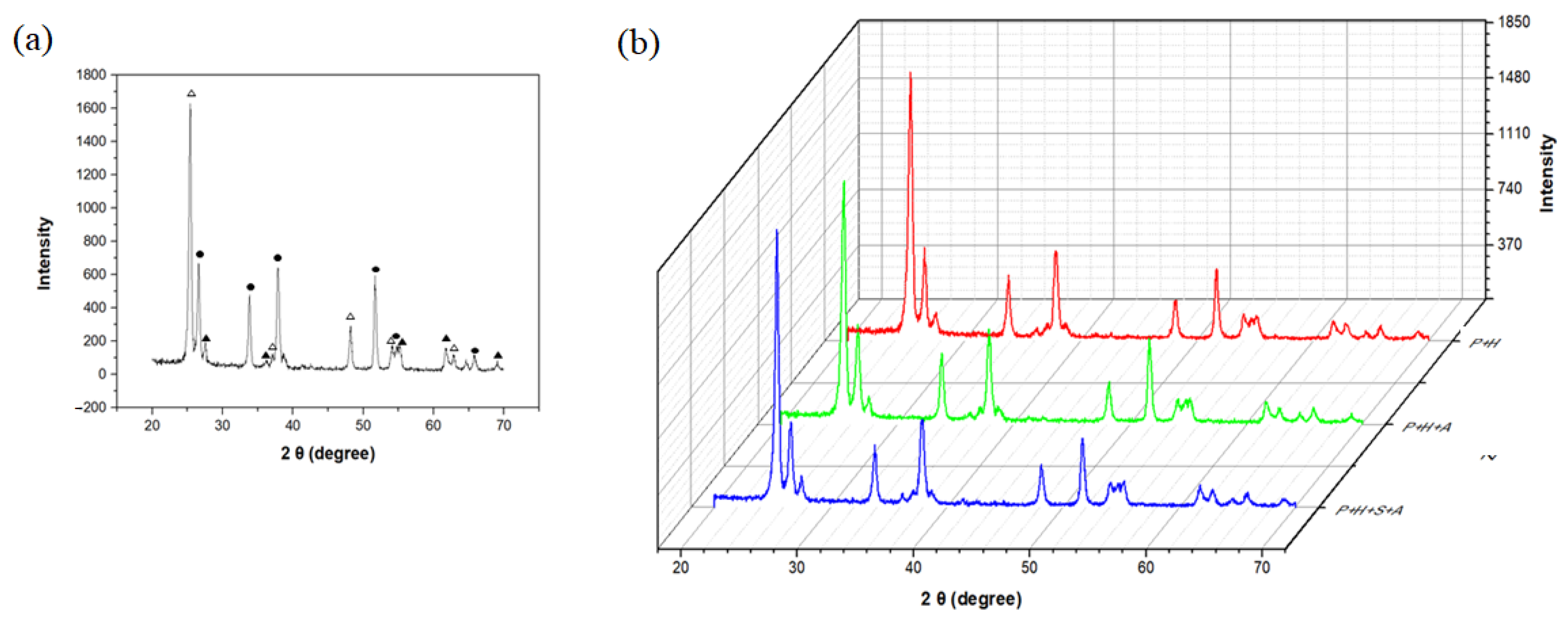
Figure 3 shows the XRD patterns of TiO2 nanoparticles deposited on FTO through microwave plasma process. As shown in Figure 3a, the weight fraction of deposited crystalline TiO2 NPs was 66% for the anatase phase and 34% for the rutile phase. As shown in Figure 3b, even through varying the deposition time to 4 or 16 min, we found that the crystallinity of TiO2 was reproduced and the ratio of phases did not change. In addition, it can be seen that there was no change in crystallinity even after heat treatment at 450 °C for 24 h to immobilize the deposited TiO2 NP layer on to FTO.
Figure 4a,b are the cross-section images of the TiO2 NP layer deposited on the FTO and the chitosan–polypyrrole (CS-PPy) polymer film deposited on the TiO2 NP layer by electrochemical method, respectively. As shown in Figure 4a, the TiO2 NP layer was deposited on the FTO substrate with a thickness of about 2 μm. Figure 4b shows that the CS-PPy conductive polymer film was deposited on the surface of the TiO2 NP layer through an electrochemical method. Figure 4c exhibits a schematic diagram showing that the TiO2 NP layer was deposited on the FTO substrate and the CS-PPy film was deposited thereon. During the electrochemical deposition, polypyrrole was connected to chitosan through hydrogen bonding, and CS-PPy/TiO2 nanocomposite conductive polymer film was formed through hydrogen bonding with TiO2 NPs and Ti–nitrogen ligand bonding. The chemical structure of the formed CS-PPy/TiO2 film is shown in Figure 4d.
Figure 5 shows the X-ray photoelectron spectroscopy (XPS) analysis results for C, O, N, and Ti, the main components of the CS-PPy/TiO2 nanocomposite conductive film. Figure 5a is the depth profile of the film. It can be seen that as the etching time increased, the CS-PPy layer on the surface was reduced by shaving, and the TiO2 NP layer was exposed, according to the increased Ti and O fractions and the decreased C and N fractions. Figure 5b,c show the XPS spectrum before and after etching for 900 s and the change in atomic concentration ratio for each element. After etching for 900 s, the fraction of TiO2 NP increased more than the CS-PPy layer and the fraction of Ti and O became closer to the ratio of Ti/O = 1:2.
For the detection of glucose using the CS-PPy/TiO2 nanocomposite conductive film as a sensor, we used a three-electrode cell system the same as the electrochemical deposition of CS-PPy layer with a scan rate of 50 mV s−1 in the range of −0.8 to +1.0 V (vs. Ag/AgCl). Glucose detection was measured by cyclic voltammetry under basic conditions (0.1 M NaOH at pH = 8.1). As shown in Figure 6a, the peak observed at about +0.13 V was according to the oxidation of glucose. Figure 6b shows a schematic diagram for the oxidation reaction of glucose on the sensor surface during the glucose detection. Glucose is oxidized to gluconolactone on the surface of sensor electrode [1], and the generated electrons can be measured by changing the current to determine the concentration of glucose in solution.
Figure 7a shows the current change according to the glucose concentration in aqueous solution using the CS-PPy/TiO2 electrode as a sensor using the chronoamperometry method, and the inset is a calibration curve for the current change according to the varied concentration of glucose. The glucose concentrations in the aqueous solutions were 1, 3, 5, 7, 9, and 11 mM, and the current was measured by applying the potential of +0.13 V for each solution. The measured currents were proportional to the concentration of glucose in each aqueous solution. The sensitivity and the limit of detection (LOD) of the CS-PPy/TiO2 sensor were determined as 302 μA mM−1 cm−2 and 6.7 μM, respectively. The detection limit was calculated using the following Equation (1):
where sb is the standard deviation of the blank and m is the sensitivity between the concentration and current (S/N = 3, confidence level = 98.1%). Figure 7b is a chronoamperometry graph comparing the sensitivity of the CS-PPy/TiO2 sensor for glucose and some substances such as ascorbic acid, uric acid, and cholesterol present in blood sample. The potential of +0.13 V was applied, and the concentrations of each substances were 0.1 mM. The large current change was detected for glucose, but the similar low current changes were observed for all comparative materials, implying the high selectivity of CS-PPy/TiO2 sensor for glucose.
LOD = 3 × sb/m
The amperometric responses of CS-PPy/TiO2 nanocomposites on FTO were also measured at an applied potential of +0.13 V (vs. Ag/AgCl) with consecutively increasing the concentration of glucose. As shown in Figure 8, the amperometric response of CS-PPy/TiO2 electrode for glucose increased linearly by increasing the concentration of glucose.
In Figure 9, the sensitivities for the detection of glucose of the CS-PPy/TiO2 glucose sensor produced by the plasma process and were compared by the sol–gel method. Using the cyclic voltammetry method, we measured the basic aqueous solutions of 1 mM glucose at a scan rate of 50 mV s−1 in the potential range of −0.8 to +1.0 V (vs. Ag/AgCl).
The sensitivities and detection limits of sensors fabricated using various metal oxides were compared. As shown in Table 2, the sensitivity of the TiO2 sensors was not very high, but it was satisfactory. In particular, the TiO2 sensor has the advantage that blood sample dilution is not required because the linear range of the TiO2 sensor covers the entire range of glucose concentrations that are actually present in human blood. Importantly, the glucose sensor fabricated by the plasma process had higher sensitivity and lower detection limit than that fabricated by the sol–gel method under the same condition. This result seems to be because the TiO2 NPs deposited by the plasma process have higher purity and crystallinity than the TiO2 NPs produced by the sol–gel method and have a larger surface area due to the relatively smaller particle size.
4. Conclusions
A highly sensitive, non-enzymatic glucose sensor based on the high-purity TiO2 nanoparticles was successfully fabricated. TiO2 nanoparticles were synthesized in thermal plasma and deposited directly on an FTO substrate followed by deposited the chitosan-polypyrrole (CS-PPy) conductive polymer films by electrochemical method to obtain the nanocomposites. The deposited TiO2 NPs were highly pure and had 66% of anatase phase. The average particle sizes of TiO2 NPs were about 20 nm and the thickness of TiO2 layer was about 2 μm. The chemical composition and structural properties of the TiO2 NP layer and the conductive polymer films were confirmed by X-ray photoelectron spectroscopy (XPS) spectra and scanning electron microscope (SEM). CS-PPy/TiO2 glucose biosensor showed high sensitivity of 302.0 µA mM−1 cm−2 (R2 = 0.9957) and low detection limit of 6.7 μM in basic solution. The higher sensitivity and lower detection limit of the glucose biosensor prepared by deposition using the plasma process rather than by sol–gel method may have been due to the higher purity and larger surface area of the TiO2 NPs deposited by the plasma process in comparison with those by the sol–gel method.
Author Contributions
Conceptualization, H.J. and S.P. (Sungho Park); methodology, J.Y., S.P. (Seokyung Park), and J.L. (Jiling Lu); writing—original draft preparation, H.J. and S.P. (Seokyung Park); writing—review and editing, S.P. (Seokyung Park) and J.L. (Jeseung Lee); supervision, S.P. (Sungho Park) and J.L. (Jeseung Lee); funding acquisition, S.P. (Sungho Park) and J.L. (Jeseung Lee). All authors have read and agreed to the published version of the manuscript.
Funding
This research was funded by National Research Foundation of Korea (NRF), grant number: 2018R1D1A1B07040898 and 2018R1D1A1B07050522.
Institutional Review Board Statement
Not applicable.
Informed Consent Statement
Not applicable.
Data Availability Statement
Not applicable.
Conflicts of Interest
The authors declare no conflict of interest.
References
- Si, P.; Huang, Y.J.; Wang, T.H.; Ma, J.M. Nanomaterials for electrochemical non-enzymatic glucose biosensors. RSC Adv. 2013, 3, 3487–3502. [Google Scholar] [CrossRef]
- Niu, X.H.; Li, X.; Pan, J.M.; He, Y.F.; Qiu, F.X.; Yan, Y.S. Recent advances in non-enzymatic electrochemical glucose sensors based on non-precious transition metal materials: Opportunities and challenges. RSC Adv. 2016, 6, 84893–84905. [Google Scholar] [CrossRef]
- Hwang, D.W.; Lee, S.; Seo, M.; Chung, T.D. Recent advances in electrochemical non-enzymatic glucose sensors—A review. Anal. Chim. Acta 2018, 1033, 1–34. [Google Scholar] [CrossRef] [PubMed]
- Wang, J. Electrochemical glucose biosensors. Chem. Rev. 2008, 108, 814–825. [Google Scholar] [CrossRef]
- Clark, L.C.; Lyons, C. Electrode systems for continuous monitoring in cardiovascular surgery. Ann. N. Y. Acad. Sci. 1962, 102, 29–45. [Google Scholar] [CrossRef] [PubMed]
- Updike, S.; Kicks, G. The enzyme electrode. Nature 1967, 214, 986–988. [Google Scholar] [CrossRef]
- Heller, A. Electrical connection of enzyme redox centers to electrodes. J. Phys. Chem. 1992, 96, 3579–3587. [Google Scholar] [CrossRef]
- Gorton, L. Carbon paste electrodes modified with enzymes, tissues, and cells. Electroanalysis 1995, 7, 23–45. [Google Scholar] [CrossRef]
- Krikstopaitis, K.; Kulys, J.; Tetianec, L. Bioelectrocatalytical glucose oxidation with phenoxazine modified glucose oxidase. Electrochem. Commun. 2004, 6, 331–336. [Google Scholar] [CrossRef]
- Tsai, T.W.; Heckert, G.; Neves, L.F.; Tan, Y.Q.; Kao, D.Y.; Harrison, R.G.; Resasco, D.E.; Schmidtke, D.W. Adsorption of glucose oxidase onto single-walled carbon nanotubes and its application in layer-by-layer biosensors. Anal. Chem. 2009, 81, 7917–7925. [Google Scholar] [CrossRef]
- Guo, M.Q.; Hong, H.S.; Tang, X.N.; Fang, H.D.; Xu, X.H. Ultrasonic electrodeposition of platinum nanoflowers and their application in nonenzymatic glucose sensors. Electrochim. Acta. 2012, 63, 1–8. [Google Scholar] [CrossRef]
- Lang, X.Y.; Fu, H.Y.; Hou, C.; Hang, G.F.; Yang, P.; Liu, Y.B.; Jiang, Q. Nanoporous gold supported cobalt oxide microelectrodes as high-performance electrochemical biosensors. Nat. Commun. 2013, 4, 2169. [Google Scholar] [CrossRef] [PubMed] [Green Version]
- Li, R.Y.; Zhang, J.J.; Wang, Z.P.; Li, Z.J.; Liu, J.K.; Gu, Z.G.; Wang, G.L. Novel graphene-gold nanohybrid with excellent electrocatalytic performance for the electrochemical detection of glucose. Sens. Actuators B Chem. 2015, 208, 421–428. [Google Scholar]
- Shen, C.C.; Su, J.; Li, X.Z.; Luo, J.J.; Yang, M.H. Electrochemical sensing platform based on Pd-Au bimetallic cluster for non-enzymatic detection of glucose. Sens. Actuators B Chem. 2015, 209, 695–700. [Google Scholar] [CrossRef]
- Yang, Y.; Wang, Y.L.; Bao, X.Y.; Li, H.C. Electrochemical deposition of Ni nanoparticles decorated ZnO hexagonal prisms as an effective platform for non-enzymatic detection of glucose. J. Electroanal. Chem. 2016, 775, 163–170. [Google Scholar] [CrossRef]
- Ghiaci, M.; Tghizadeh, M.; Ensafi, A.A.; Zandi-Atashbar, N.; Rezaei, B. Silver nanoparticles decorated anchored type ligands as new electrochemical sensors for glucose detection. J. Taiwan Inst. Chem. E 2016, 63, 39–45. [Google Scholar] [CrossRef]
- Thanh, T.D.; Balamurugan, J.; Lee, S.H.; Kim, N.H.; Lee, J.H. Effective seed-assisted synthesis of gold nanoparticles anchored nitrogen-doped graphene for electrochemical detection of glucose and dopamine. Biosens. Bioelectron. 2016, 81, 259–267. [Google Scholar] [CrossRef]
- Zhu, H.; Li, L.; Zhou, W.; Shao, Z.P.; Chen, X.J. Advances in non-enzymatic glucose sensors based on metal oxides. J. Mater. Chem. B. 2016, 4, 7333–7349. [Google Scholar] [CrossRef] [PubMed]
- Hovancova, J.; Sisolakova, I.; Orinakova, R.; Orinak, A. Nanomaterial-based electrochemical sensors for detection of glucose and insulin. J. Solid State Electr. 2017, 21, 2147–2166. [Google Scholar] [CrossRef]
- Sabu, C.; Henna, T.K.; Raphey, V.R.; Nivitha, K.P.; Pramod, K. Advanced biosensors for glucose and insulin. Biosens. Bioelectron. 2019, 141, 111201. [Google Scholar] [CrossRef]
- Bao, S.J.; Li, C.M.; Zang, J.F.; Cui, X.Q.; Qiao, Y.; Guo, J. New nanostructured TiO2 for direct electrochemistry and glucose sensor applications. Adv. Funct. Mater. 2008, 18, 591–599. [Google Scholar] [CrossRef]
- Mu, Y.; Jia, D.; He, Y.; Miao, Y.; Wu, H.-L. Nano nickel oxide modified non-enzymatic glucose sensors with enhanced sensitivity through an electrochemical process strategy at high potential. Biosens. Bioelectron. 2011, 26, 2948–2952. [Google Scholar] [CrossRef]
- Wang, L.; Fu, J.; Hou, H.; Song, Y. A facile strategy to prepare Cu2O/Cu electrode as a sensitive enzyme-free glucose sensor. Int. J. Electrochem. Sci. 2012, 7, 12587–12600. [Google Scholar]
- Zhou, D.-L.; Feng, J.-J.; Cai, L.-Y.; Fang, Q.-X.; Chen, J.-R.; Wang, A.-J. Facile synthesis of monodisperse porous Cu2O nanospheres on reduced graphene oxide for non-enzymatic amperometric glucose sensing. Electrochim. Acta 2014, 115, 103–108. [Google Scholar] [CrossRef]
- Hou, C.; Xu, Q.; Yin, L.; Hu, X. Metal-organic framework templated synthesis of Co3O4 nanoparticles for direct glucose and H2O2 detection. Analyst 2012, 137, 5803–5808. [Google Scholar] [CrossRef]
- Masoomi-Godarzi, S.; Khodadadi, A.A.; Vesali-Naseh, M.; Mortazavi, Y. Highly stable and selective non-enzymatic glucose biosensor using carbon nanotubes decorated by Fe3O4 nanoparticles. J. Electrochem. Soc. 2014, 161, B19–B25. [Google Scholar] [CrossRef]
- Chen, Y.; Zhang, H.; Xue, H.; Hu, X.; Wang, G.; Wang, C. Construction of a non-enzymatic glucose sensor based on copolymer P4VP-co-PAN and Fe2O3 nanoparticles. Mater. Sci. Eng. C 2014, 35, 420–425. [Google Scholar] [CrossRef]
- Ye, Y.; Wang, P.; Dai, E.; Liu, J.; Tian, Z.; Liang, C.; Shao, G. A novel reduction approach to fabricate quantum-sized SnO2-conjugated reduced graphene oxide nanocomposites as non-enzymatic glucose sensors. Phys. Chem. Chem. Phys. 2014, 16, 8801–8807. [Google Scholar] [CrossRef] [Green Version]
- Si, P.; Ding, S.J.; Yuan, J.; Lou, X.W.; Kim, D.H. Hierarchically structured one-dimensional TiO2 for protein immobilization, direct electrochemistry, and mediator-free glucose sensing. ACS Nano 2011, 5, 7617–7626. [Google Scholar] [CrossRef]
- Chen, J.S.; Xu, L.; Xing, R.Q.; Song, J.; Song, H.W.; Liu, D.L.; Zhou, J. Electrospun three-dimensional porous CuO/TiO2 hierarchical nanocomposites electrode for nonenzymatic glucose biosensing. Electrochem. Commun. 2012, 20, 75–78. [Google Scholar] [CrossRef]
- He, M.Q.; Bao, L.L.; Sun, K.Y.; Zhao, D.X.; Li, W.B.; Xia, J.X.; Li, H.M. Synthesis of molecularly imprinted polypyrrole/titanium dioxide nanocomposites and its selective photocatalytic degradation of rhodamine B under visible light irradiation. Express Polym. Lett. 2014, 8, 850–861. [Google Scholar] [CrossRef] [Green Version]
- Bai, J.; Zhou, B.X. Titanium dioxide nanomaterials for sensor applications. Chem. Rev. 2014, 114, 10131–10176. [Google Scholar] [CrossRef] [PubMed]
- Yang, Q.; Long, M.; Tan, L.; Zhang, Y.; Ouyang, J.; Liu, P.; Tang, A.D. Helical TiO2 nanotube arrays modified by Cu-Cu2O with ultrahigh sensitivity for the nonenzymatic electro-oxidation of glucose. ACS Appl. Mater. Interface 2015, 7, 12719–12730. [Google Scholar] [CrossRef] [PubMed]
- Al-Mokaram, A.M.A.A.A.; Yahya, R.; Abdi, M.M.; Mahmud, H.N.M.E. The development of non-enzymatic glucose biosensors based on electrochemically prepared polypyrrole-chitosan-titanium dioxide nanocomposite films. Nanomaterials 2017, 7, 129. [Google Scholar] [CrossRef] [Green Version]
- Jeong, H.; Yoo, J.; Park, S.K.; Park, S.; Lee, J.S. High-purity core/shell structured nanoparticles synthesis using high-frequency plasma technology and atomic layer deposition. Vacuum 2020, 179, 109556. [Google Scholar] [CrossRef]
Figure 1.
Schematic diagram of (a) a three-electrode measuring system and (b) the preparing CS-PPy/TiO2 nanocomposite films on FTO.
Figure 1.
Schematic diagram of (a) a three-electrode measuring system and (b) the preparing CS-PPy/TiO2 nanocomposite films on FTO.

Figure 2.
(a) TEM image and (b) EDX data of TiO2 nanoparticles prepared by thermal plasma process.

Figure 3.
XRD patterns of (a) deposited TiO2 NPs on FTO electrode (Δ: anatase phase, ▲: rutile phase, ●: FTO) and (b) after deposition and after immobilization (in order from top to bottom, after 4 min of deposition, after 16 min of deposition, and after heat treatment (450 °C)).
Figure 3.
XRD patterns of (a) deposited TiO2 NPs on FTO electrode (Δ: anatase phase, ▲: rutile phase, ●: FTO) and (b) after deposition and after immobilization (in order from top to bottom, after 4 min of deposition, after 16 min of deposition, and after heat treatment (450 °C)).

Figure 4.
SEM images of the cross-section of (a) TiO2 deposited on the FTO electrode and (b) CS-PPy conductive polymer film deposited on (a). (c) Schematic procedure of depositing CS-PPy conductive polymer on TiO2 deposited on FTO and (d) chemical structure of a CS-PPy/TiO2 films.
Figure 4.
SEM images of the cross-section of (a) TiO2 deposited on the FTO electrode and (b) CS-PPy conductive polymer film deposited on (a). (c) Schematic procedure of depositing CS-PPy conductive polymer on TiO2 deposited on FTO and (d) chemical structure of a CS-PPy/TiO2 films.

Figure 5.
(a) XPS depth profile of CS-PPy/TiO2 glucose sensor. XPS survey spectra and atomic concentration fraction of (b) before sputtering and (c) after 900 s sputtering.
Figure 5.
(a) XPS depth profile of CS-PPy/TiO2 glucose sensor. XPS survey spectra and atomic concentration fraction of (b) before sputtering and (c) after 900 s sputtering.

Figure 6.
Cyclic voltammograms of CS-PPy/TiO2 sensor in 0.1 M NaOH solution (a) with 1 mM glucose and without glucose and (b) reaction on the sensor surface during the glucose detection.
Figure 6.
Cyclic voltammograms of CS-PPy/TiO2 sensor in 0.1 M NaOH solution (a) with 1 mM glucose and without glucose and (b) reaction on the sensor surface during the glucose detection.

Figure 7.
Chronoamperograms of CS-PPy/TiO2 glucose sensor in 0.1 M NaOH solution at +0.13 V with (a) varied glucose concentration (the inset shows the steady-state calibration curve) and (b) the different substances.
Figure 7.
Chronoamperograms of CS-PPy/TiO2 glucose sensor in 0.1 M NaOH solution at +0.13 V with (a) varied glucose concentration (the inset shows the steady-state calibration curve) and (b) the different substances.

Figure 8.
Amperometric responses to the consecutive addition of glucose solution in 0.1 M NaOH solution at +0.13 V.
Figure 8.
Amperometric responses to the consecutive addition of glucose solution in 0.1 M NaOH solution at +0.13 V.

Figure 9.
Cyclic voltammograms of CS-PPy/TiO2 prepared by plasma process and sol–gel process.


Table 1.
Dependence on the deposition time for the average particle sizes of deposited TiO2 NPs.
| Deposition Time (min) | Average Particle Size (nm) |
|---|---|
| 2 | 19.2 |
| 4 | 18.7 |
| 8 | 20.9 |
| 16 | 19.7 |
Table 2.
Comparison of biosensor characteristics according to the metal oxide NPs.
| Metal Oxide | Sensitivity (µA mM−1 cm−2) | Linear Range (mM) | LOD (µM, S/N = 3) | Reference |
|---|---|---|---|---|
| NiO | 43.9 | 0.001–0.11 | 0.16 | [22] |
| Cu2O | 62.29 | 0.05–6.75 | 37 | [23] |
| Cu2O | 185 | 0.01–6 | 0.05 | [24] |
| Co3O4 | 520.7 | 0.005–0.8 | 0.13 | [25] |
| Fe3O4 | 238.7 | 0.5–7 | 15 | [26] |
| Fe2O3 | 1382.8 | 0.0025–0.58 | 0.58 | [27] |
| SnO2 | 1930 | 0.050–0.500 | 13.35 | [28] |
| TiO2 a | 0.008 | 1–14 | 614 | [29] |
| TiO2 b | 254.4 | 1–9 | 62 | this work |
| TiO2 c | 302.0 | 1–11 | 6.7 | this work |
a Electrochemical deposition. b Sol–gel method. c Plasma thermal deposition.
Publisher’s Note: MDPI stays neutral with regard to jurisdictional claims in published maps and institutional affiliations. |
© 2021 by the authors. Licensee MDPI, Basel, Switzerland. This article is an open access article distributed under the terms and conditions of the Creative Commons Attribution (CC BY) license (https://creativecommons.org/licenses/by/4.0/).
Share and Cite
MDPI and ACS Style
Jeong, H.; Yoo, J.; Park, S.; Lu, J.; Park, S.; Lee, J. Non-Enzymatic Glucose Biosensor Based on Highly Pure TiO2 Nanoparticles. Biosensors 2021, 11, 149. https://0-doi-org.brum.beds.ac.uk/10.3390/bios11050149
AMA Style
Jeong H, Yoo J, Park S, Lu J, Park S, Lee J. Non-Enzymatic Glucose Biosensor Based on Highly Pure TiO2 Nanoparticles. Biosensors. 2021; 11(5):149. https://0-doi-org.brum.beds.ac.uk/10.3390/bios11050149
Chicago/Turabian StyleJeong, Hongin, Jhongryul Yoo, Seokyung Park, Jiling Lu, Sungho Park, and Jeseung Lee. 2021. "Non-Enzymatic Glucose Biosensor Based on Highly Pure TiO2 Nanoparticles" Biosensors 11, no. 5: 149. https://0-doi-org.brum.beds.ac.uk/10.3390/bios11050149
Note that from the first issue of 2016, this journal uses article numbers instead of page numbers. See further details here.