1. Introduction
There is significant discussion within the scientific community concerning the distinction and interrelation between self-organization (SO) [
1,
2] and self-organized critical (SOC) processes [
3,
4,
5,
6,
7,
8]. This research exhibits real case studies of the underlying relationships between these processes, especially under strong non-equilibrium conditions, which are typical for friction.
It was discovered by I. Prigogine that, under certain conditions, non-equilibrium thermodynamic systems absorb matter and energy from the surrounding environment in order to make a qualitative jump in complexity by forming dissipative structures [
1]. This was a focus of our previous research [
2] and the current study is a continuation of the development of this approach. It is strongly contended by the authors of this study that any advancement in this research direction requires reliable experimental investigations (case studies). The relevant field of applied science and engineering is known as tribology, which is concerned with the interrelation between physical/chemical phenomena that emerge under the predominantly non-equilibrium conditions in tribological applications [
9]. The cutting process constitutes a unique environment in which such phenomena can be studied under severely tribological conditions that are very far from equilibrium, which are rarely observable in any other field.
Cutting is a complex tribological process that usually undergoes very high temperatures (within the range of 700–1000 °C, and even above [
9]), heavy loads (within the range of 1–2 GPa and more) and strongly non-equilibrium states throughout the entire tribo-system [
10,
11,
12].
Temporal effects strongly associated with self-organization are chiefly considered in chemical, biological and material fields of science [
13,
14,
15,
16,
17,
18,
19,
20]. A limited amount of scientific literature exists on the temporal wear behavior of materials [
21,
22]; in particular, the atomic/nano-scale surface tribo-ceramic films that are generated under the outlined conditions [
9].
It should be noted that a self-organized critical (SOC) process could also develop under these conditions [
23]. Limited information is available in published studies regarding the relationship between temporal self-organization (SO) processes and self-organized criticality (SOC) [
24,
25,
26,
27].
It is known that strong adhesive bonds are periodically formed and destroyed during cutting, which results in attrition wear [
28]. Moreover, the intensive adhesive interaction between the tool and the workpiece during the machining of sticky materials (such as stainless steels) eventually leads to the catastrophic tribological mode of seizure and the generation of large buildups [
29]. These buildups are dynamic complex structures [
29] driven by a stick–slip phenomenon during friction, which is associated with the self-organized critical (SOC) process [
8]. The buildup is structurally similar to a composite “third body” [
29], which consists of heavily deformed particles of the machined material as well as various compounds created during cutting by the complex interactions between the tool, the workpiece and the environment [
29]. On the one hand, the “ceramic-like” buildup layer provides significant protection to the tool surface [
29]. On the other hand, the structural stability of a buildup layer is very poor due to its avalanche-like behavior [
8]. An avalanche-like release of energy (dissipation) takes place during the moment at which the buildups become separated from the surface of a cutting tool, which initiates self-organization (via the formation of a tribo-film) in this area.
It is known that the system must be in a highly non-equilibrium state in order for self-organization with the formation of dissipative structures to be initiated [
30]. Moreover, the system must intensely deviate not only from the equilibrium but also from the stationary state [
31]. Thus, the tribo-system needs to be quite heavily loaded, and at the same time, undergo significant dissipation for self-organization, with dissipative structure formation to commence.
Since the processes that develop during self-organization (SO) with dissipative structure formation have an intensely negative entropy production, the overall growth of entropy within the system is actually lower. This means that the processes in a tribo-system develop in an avalanche-like manner, thereby absorbing a significant portion of the frictional energy, which would otherwise be expended on the wear process.
Conversely, SOC processes begin to aggregate in an avalanche-like manner in order to cause significant energy dissipation and entropy production. As these “avalanches” develop, the SOC significantly increases the instability of the stationary state. This is precisely what is needed to initiate self-organization with the formation of dissipative structures (tribo-films), under which, in contrast to the previous process, the dissipation of energy, entropy production and the ensuing wear rate decrease like an avalanche. Therefore, the SOC increases energy dissipation in an avalanche-like manner, thereby facilitating the transition towards self-organization.
This paper investigates the dynamic interactions between various self-organizing processes that coincide with temporal wear processes during cutting with buildup edge formation [
5].
2. Finite Element Process Modeling
Finite element modeling (FEM) is essential for evaluating the conditions (such as temperature/stress profiles) present at the cutting zone. This step is necessary for a better understanding and control of the wear mechanisms under a machining process with a prevalent buildup edge formation [
29]). During metal cutting, the severe plastic deformation of the workpiece material is responsible for the growth of temperature/stress, which results in severe tribological conditions [
2]. One of the major challenges of modeling the temperature/stress profiles within the cutting zone during stainless steel machining under wet conditions is presented by the complexity of the machining processes associated with buildup edge formation. It should be noted that this FEM-based approach is quite novel. In this case, simulations of metal machining during turning require a fundamental understanding of the deformation conditions in the relevant deformation zones, as well as the strain rates and frictional conditions at the tool/workpiece interface. Cutting temperature/stress profiles are critical for understanding and controlling a machining process with buildup edge formation [
29]).
All modeling in this study was conducted by a Third Wave Systems AdvantEdge™ simulation software (version 7.8), which employs advanced finite element models suitable for machining operations. A method of continuous chip formation was developed for a cutting length of 3 mm. The mechanical properties of the workpiece material (an austenitic AISI 304 stainless steel) were obtained using the FEM program database. The material and coolant properties used for the model input, as well as for the friction coefficient, are given in
Table 1.
The AdvantEdge software combines the Lagrangian method with adaptive remeshing capabilities in order to address the non-linearities generated by high strain rates and plastic deformation inherent to the machining processes.
The cutting edge was defined as ideally rigid, in accordance with CNMG 120408 MS Grade KCM25 (Kennametal) inserts used in the experiments. The cutting parameters and tool code geometry used in the simulation are listed in
Table 2 (see experimental).
The 2D models of temperature/stresses are presented in
Figure 1.
Figure 1 presents FEM data (2D stress/temperature profiles) at the cutting zone with buildup formation.
As can be seen in
Figure 1, high temperatures (around 740 °C) and loads (around 1.5–2 GPa) are generated on the cutting edge under analyzed cutting conditions.
These severe conditions strongly influence the surface phenomena, which unfold during the wear of the the tribo-system.
3. Materials and Methods
The cutting parameters used in this work are listed in
Table 2.
The cemented carbide cutting insert used for the cutting tests was CNMG120408-MP (according to ISO 1832). The workpiece material analyzed in this work is an austenitic AISI 304 stainless steel (
Table 1). Semi-finish turning cutting tests were performed. A CNC Okuma Crown L1060 lathe was used for the cutting tests. All turning tests were conducted at a cutting speed of 320 m/min, feed rate of 0.2 mm/rev and depth of cut of 1 mm under wet conditions, using a semi-synthetic coolant with 7% concentration. The cutting conditions were based on the industrial practice. In order to remove buildups, Aqua Regia etchant was used.
Cross-section studies of the cutting tools and wear pattern investigations were performed using a Vega 3-TESCAN scanning electron microscope (SEM) (Vega 3-TESCAN, TESCNA, Brno Kohoutovice, Czech Republic). The wear mechanism and morphology of the worn cutting inserts were also evaluated through the electron backscatter diffraction (EBSD, JSM-7600F Schottky, Jeol Ltd., Tokyo, Japan); Field Emission Scanning Electron Microscope (FE-SEM, JSM-F100, Jeol Ltd., Tokyo, Japan) method. The micro-mechanical characteristics (hardness and reduced elastic modulus) of the coatings and corresponding carbide substrates were measured by a Fischerscope HM2000 Hardness Tester (Fischer, Sindelfingen, Germany) at a load of 20 mN. A Vickers indenter geometry was used for this analysis. In order to evaluate the wear performance during the cutting tests, progressive 3D studies of wear volume were carried out with an Infinite Focus G5 focus variation microscope (Optimax, Alicona, Austria).
The surface and chemical composition of the formed tribo-films on the surface of cutting tool were analyzed by X-ray photoelectron spectroscopy (XPS, AXIS Nova, Kratos Analytical Inc., Manchester, UK), AXIS Supra spectrometer equipped with a hemispherical energy analyzer and an Al anode source for X-ray generation. A monochromatic Al K-α X-ray (1486.6 eV) source was operated at 15 kV. The system base pressure was no higher than 1.0 × 10⁻⁹ Torr, with an operating pressure that did not exceed 2.0 × 10⁻⁸ Torr. The samples were sputter-cleaned for 4 min by a 4 kV Ar+ beam prior to the collection of any spectra. A 110 μm beam was used for the data collected from the samples. All survey spectra were gathered at a pass energy of 160 eV. High-resolution data were collected at a pass energy of 40 eV. The spectra were obtained at a 90° takeoff angle and Kratos’ charge compensation ensured the neutralization of all samples. The data were calibrated using a C1s signal of C–C at 284.8 eV. Data analysis was performed in Casa XPS version 2.3.18PR1.0 software (version 2.3.24).
4. Results and Discussion
Figure 2 shows the cross-section of the carbide tool with CVD alumina multilayer TiN/TiCN/Al
2O
3 coating.
Cutting edge profiles were evaluated using an Alicona Infinity Focus white light microscope equipped with focus variation and 3D capabilities (
Figure 3).
Investigations were carried out in two stages:
-With buildups forming in situ;
-With buildups etched out by chemical etching to prevent the screening effect.
This approach enables the distinction of different wear mechanisms and the assessment of their contribution to the entire tribo-system’s performance.
The obtained data also outline the progression of the buildup size with respect to wear time. The size of the buildup edge (BUE) tends to strongly fluctuate with a growing length of cut.
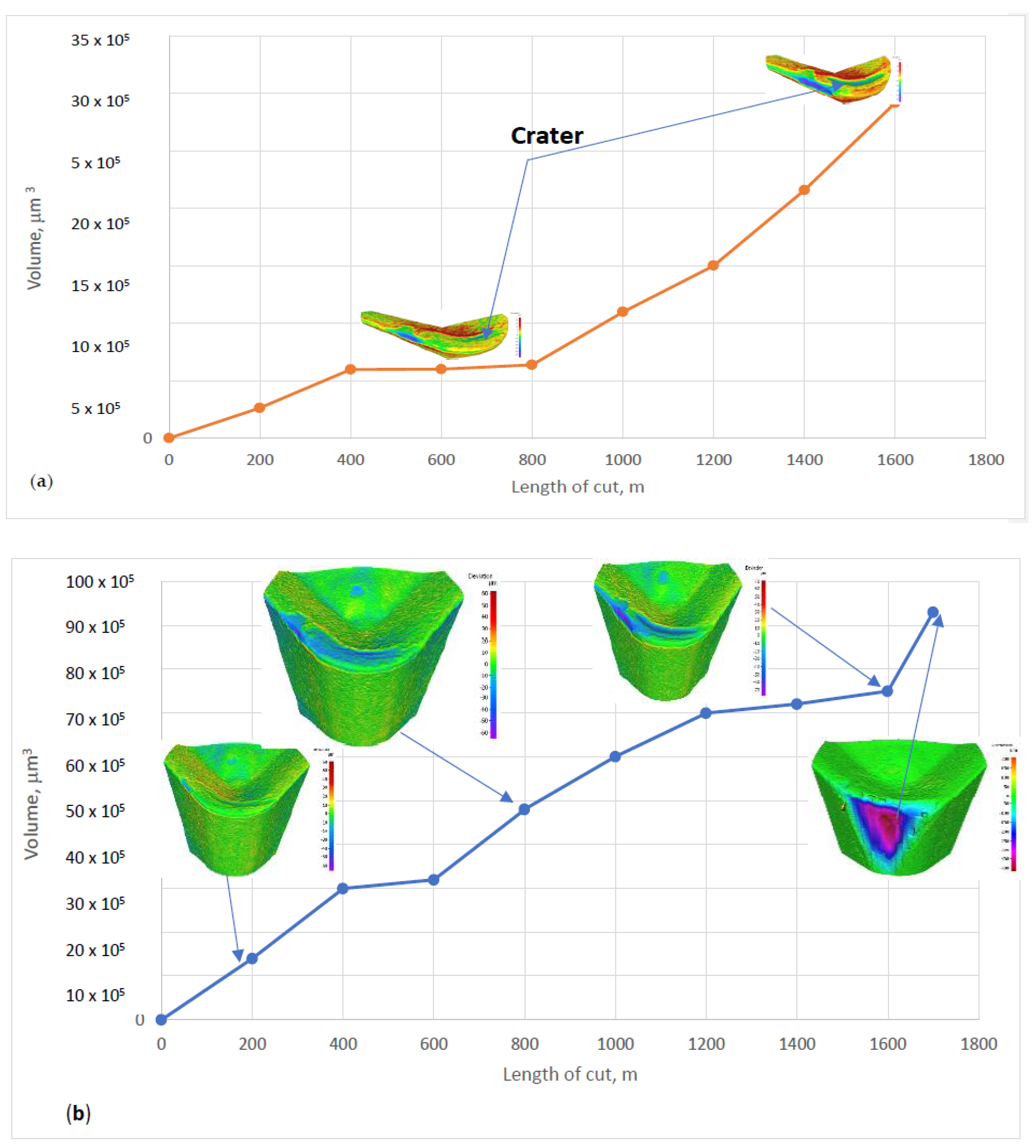
Figure 3 presents 3D Alicona progressive wear studies after each 200 m length of cut.
Figure 3a depicts the significant progression of BUE with the length of cut. The BUE instability is demonstrated by the periodical volatility of the BUE heights in relation to the previous passes (
Figure 3a). XPS studies of the surface in close proximity to the buildup were performed after a similar length of cut. Typical XPS results at the corresponding wear regions are presented in
Figure 3b.
Figure 4 shows the typical XPS spectra of the surface of the coated tool after wear. In the initial state, only the corundum (Al
2O
3) phase is present on the surface of the CVD-coated tool, as confirmed by XRD analysis [
32]. After wear, the sapphire tribo-phase [
2] starts to form at nano-scale [
9] in the corresponding wear regions (
Figure 4).
It is interesting to note that the quantity of sapphire tribo-films that form on the surface of the ceramic coating exhibits the opposite trend to BUE formation, with respect to the length of cut (
Figure 3b). The formation of these tribo-films follows an unstable pattern, alternating between peaks and troughs in contrast with the BUE height. As can be seen in
Figure 3b the sapphire tribo-film content reached 82% at a cutting length of 200 m. As the buildup height grew from 13 to 17 μm (
Figure 3a), at a cutting length increment of 200 to 400 m, the amount of sapphire tribofilms content slightly decreased to 80% (
Figure 3b). When the buildup height had reached 48 μm at a 600 m length of cut, the sapphire tribofilm content decreased to 70%. It can be concluded that the decrease in the amount of sapphire tribo-films can be associated with a corresponding decrease in the thermomechanical loads on the layer of tribo-films. Consequently, the formation of a buildup layer assumes a portion of the surface protective functions, alleviating friction conditions on the tribo-films. At a cutting length of 800 m, the buildup becomes detached and a new buildup layer begins to form (its height is 15 μm). The detachment of the old buildup and the formation of a new small buildup increases the thermomechanical load on the tribo-film layer. Accordingly, as a result of the adaptive response of the friction surface, the amount of sapphire tribo-films increases by up to 88% at a length of cut of 800 m. At a length of cut of 1000 m, the height of the new buildup reaches 54 μm. Once again, this buildup takes over a part of the surface protective functions, reducing the thermomechanical load on the tribo-film layer. Accordingly, the amount of sapphire tribofilms was reduced to 63% at this cutting length. At a length of cut of 1200 m, the new buildup layer became partially detached once again, with a consequent partial loss of its protective functions. The thermomechanical load on the tribo-film layer was thus increased. As a result, the amount of sapphire tribo-films also rose to 70% at a length of cut of 1200 m. Further growth of the buildup layer’s height to 60 μm at a length of cut of 1400 m resulted in a decrease in the thermomechanical load on the tribofilm layer, as well as a corresponding reduction of the amount of sapphire tribofilms to 57%. The next partial buildup detachment occurred at a cutting length of 1600 m, resulting in an increase in the thermomechanical load on the tribo-film layer and a consequent growth of the sapphire tribo-phase content to 63%.
Figure 5 records the quantitative 3D wear data (
Figure 5a) and crater wear volumes (
Figure 5b) vs. the time of cut.
Figure 5 presents tool wear data with the buildups, which have been chemically etched-out. The wear curve consists of the following typical stages: the initial running-in stage (up to a length of cut of 400 m), the short stable wear stage and the stage of accelerated wear caused by the intensification of crater wear (at a length of cut exceeding 800 m,
Figure 5b). Crater wear begins to form after 800 m (
Figure 5b), mostly due to the chips sliding along the rake surface of the tool [
2]. This process continues to unfold until the end of the tool life (
Figure 5a,b). The growth of crater wear, in combination with flank wear, eventually results in the failure of the entire tribo-system (see the 3D image of the final wear stage presented in
Figure 5a).
As was outlined previously, the process of BUE formation is governed by the stick–slip phenomena [
8]. Corresponding patterns of these phenomena are presented in the SEM images of typical buildups in
Figure 6.
Figure 6a depicts a BUE during the initial running-in stage and
Figure 6b shows the progression of BUE throughout the consequent wear stages (see
Figure 5a). It is interesting to note that, at the very beginning of wear, during the running-in stage (see
Figure 3 and
Figure 5a), the rise of intensive thermomechanical processes (due to the adhesive interactions at the tool/chip interface) results in heavy frictional loads and temperatures within the cutting zone. This is a consequence of the stick–slip phenomenon (
Figure 6a), which is directly related to the self-organized critical process [
3]. The resulting growth of entropy production [
3,
4] immediately prompts an adaptive response from the surface engineered layer to the external stimuli and directly leads to the intensification of energy dissipation (self-organization) [
1]. The tribo-films are generated at a highly rapid rate at the initial stage of friction (
Figure 3b). A similar trend was already presented in [
9].
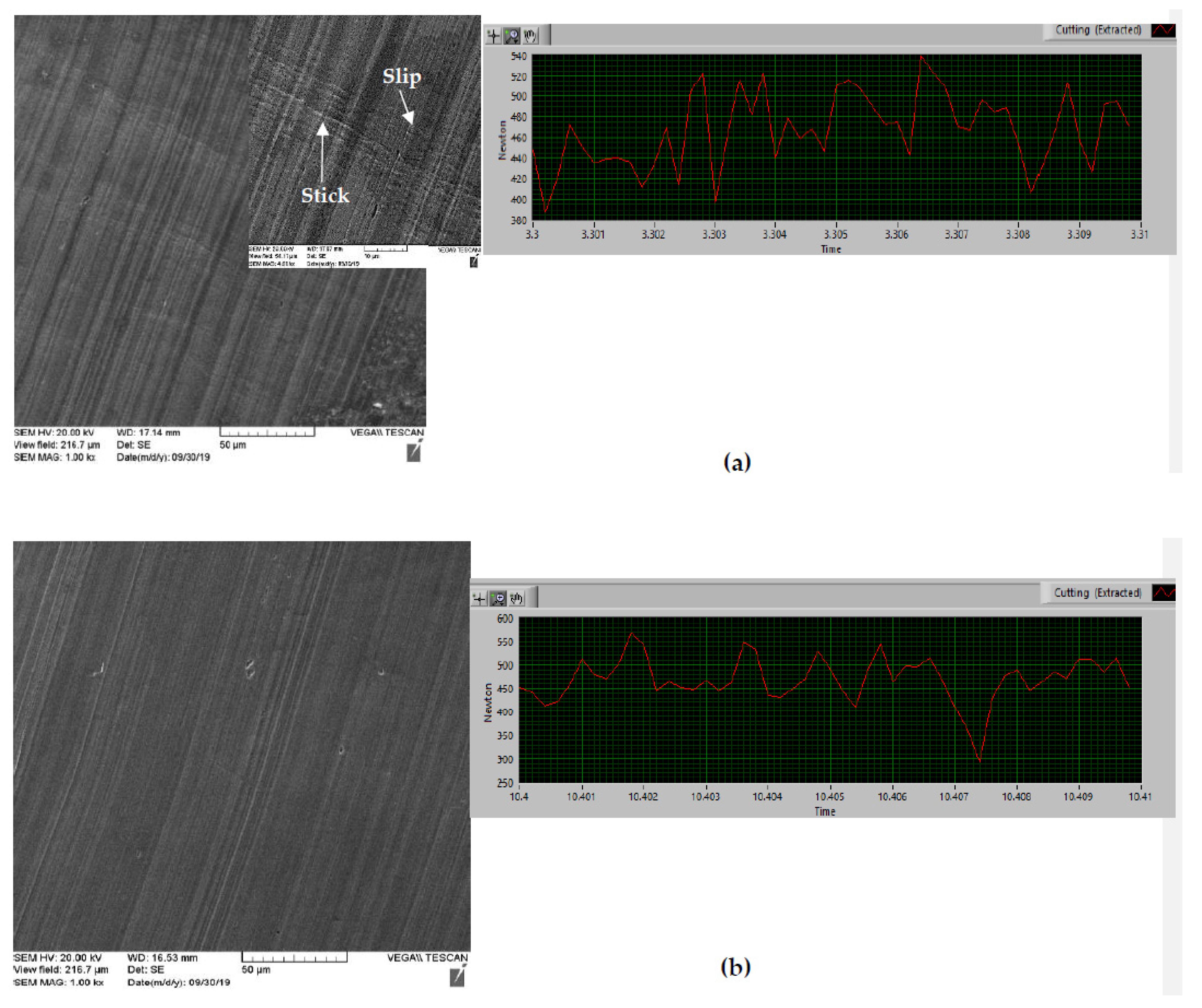
SEM images of the chip undersurface, as well as cutting force data, confirm these phenomena (
Figure 7).
The stick–slip phenomenon [
8] occurs on the chip/tool surface at the moment of the most intensive buildup edge formation (wave-like patterns indicated by arrows, at a length of cut of 1000 m, see
Figure 7a). The most intensive spikes of frictional forces occur at the same length of cut (
Figure 7a). They strongly diminish at the next length of cut of 1200 m (
Figure 7b). Cutting force spikes become less intense (
Figure 7b) and wave-like patterns on the chips undersurface are practically eliminated at the next moment of cut (
Figure 7b). This outcome can be attributed to the generation of thermal barrier tribo-films on the friction surface at the corresponding moment of wear (
Figure 3b).
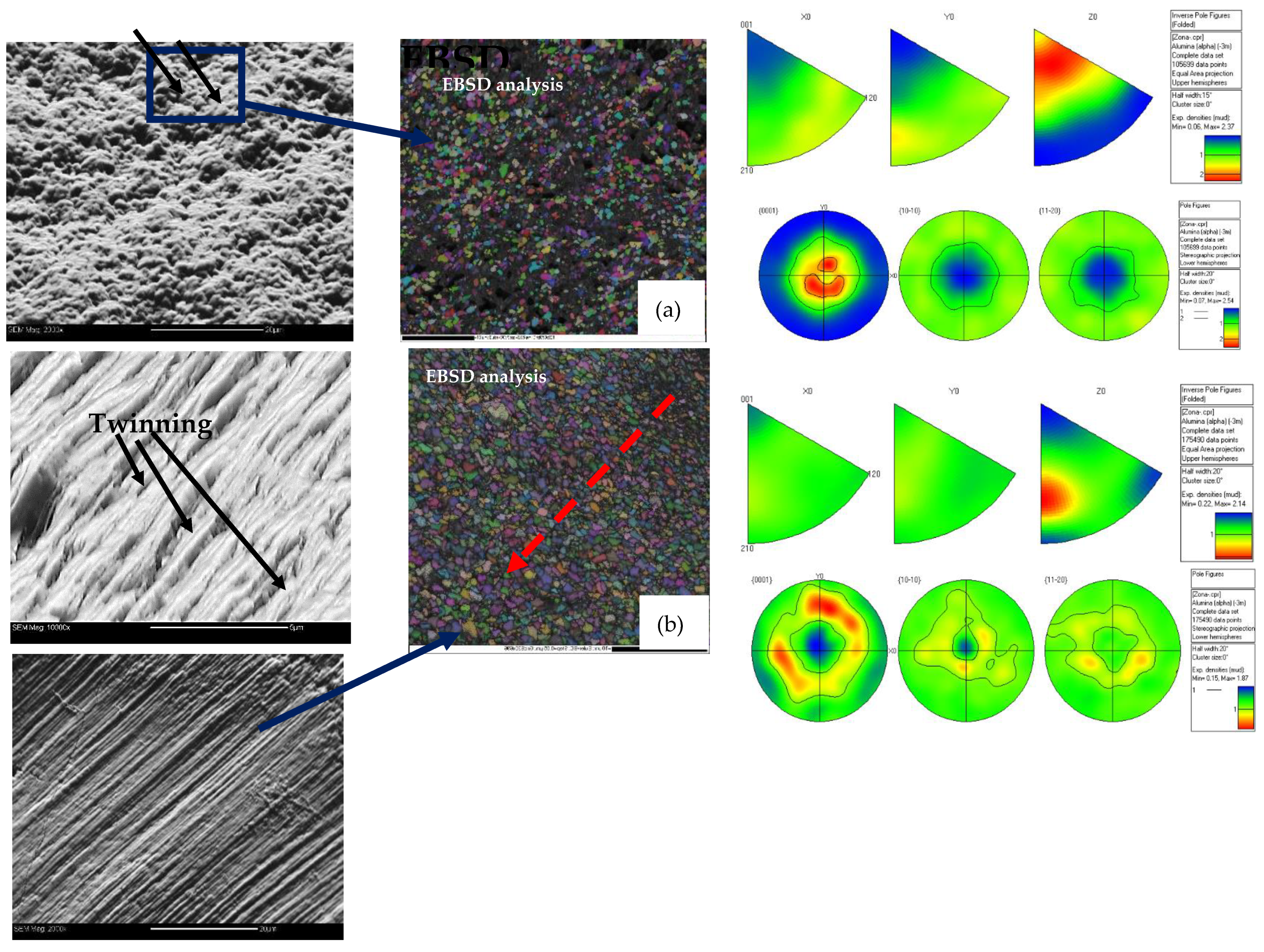
Another micro-scale phenomenon known as deformation twinning [
33], occurring on the alumina coating layer during various stages of wear, was caused by the repetitive shock loading that arose from the periodical formation and breakage of buildups (
Figure 8).
Figure 8 presents the SEM and EBSD images of the coated tool surface (in the region close to the tip) during the initial state (
Figure 8a) and after wear (
Figure 8b) with chemically etched buildup. The SEM image of the surface morphology at the initial state indicates the presence of alveoli all over the surface (
Figure 8a). The electron backscattered diffraction (EBSD) images of the initial state (
Figure 8a) depict the crystalline structure of the as-deposited surface coating layer. The crystal orientation map images indicate the absence of any plastic deformation and a clear grain orientation distribution function (ODF) of (0 0 1), (2 1 0) and (1 2 0) (see the pole figures in
Figure 8a). The pole figures indicate a (0 0 1) preferred orientation in the range of 0–20 degrees, predominantly perpendicular to the surface, which is typical for a CVD alpha-alumina orientation structure after deposition [
33,
34,
35,
36]. SEM images of the post-wear surface morphology (
Figure 8b) show that the alveoli disappear due to the intensive metal flow at the chip/tool interface. This leads to the formation of twinning patterns (
Figure 8b) caused by the plastic deformation of the surface layer. The crystal orientation map image also reveals intensive plastic deformation on the tool surface during cutting. FEM data indicate that grain refinement of the alumina coating layer could be caused by heavy load/high-temperature conditions at the cutting edge, (
Figure 1). Surface deformation is more intense near the tool tip, decreasing with distance from the edge (see red arrow,
Figure 8b). The reduction of grain elongation in this direction can be clearly seen. The preferred crystal (0 0 1) orientation is still there, but it is "blurred" and the (0 0 1) texture is within a range of 30–60 degrees in the direction perpendicular to the surface. Such a change in crystallographic orientation on the surface layer can be attributed to the aforementioned severe plastic deformation on the friction surface, which is confirmed by the change in the preferred crystal orientation to (2 1 0) and (1 2 0).
This performance affects the tool’s underlying surface area and causes twinning in the alumina coating layer (
Figure 8b). Twins are possible channels for decreasing the system’s entropy [
34]. This process could also be associated with yet another self-organization process that develops within the tribo-system at the micro-scale [
33,
34,
35,
36].
Energy dissipation occurs on three levels: the macro-scale (formation and detachment of buildup on a scale of tens of microns), the nano-scale (tribo-film formation through a strongly non-equilibrium process) and the micro-scale (twinning on the surface of the several-microns-thick ceramic layer). These multi-scale processes occur both in a state of equilibrium and in a strongly non-equilibrium state.


 ,
, 


