Effect of Fabric Integration on the Physical and Optical Performance of Electroluminescent Fibers for Lighted Textile Applications


Department of Electrical, Computer Engineering, Drexel University, Philadelphia, PA 19104, USA
*
Author to whom correspondence should be addressed.
Fibers 2018, 6(3), 50; https://0-doi-org.brum.beds.ac.uk/10.3390/fib6030050
Submission received: 20 April 2018
/
Revised: 12 July 2018
/
Accepted: 13 July 2018
/
Published: 17 July 2018
(This article belongs to the Special Issue Electronically Active Textiles)
Abstract
:The advent of electroluminescent (EL) fibers, which emit light in response to an applied electric field, has opened the door for fabric-integrated light emission and displays in textiles. However, there have been few technical publications over the past few years about the performance of these light emitting fibers inside functional fabrics. Thus, there is limited information on the effect of integration on the physical and optical performance of such devices. In this work, alternating current powder-based EL (ACPEL) fibers were evaluated under a range of operating conditions both inside and outside of a knit matrix to understand how the EL fiber device performance changed inside a functional fabric. The device efficiency, adjustable brightness, and mechanical properties of these fibers are presented. The effects of fabric integration on the light-emitting fibers as well as the supporting knit fabric are discussed as they relate to the practical applications of this technology.
1. Introduction
The merging of electronics and textiles has given rise to garments and upholstery with new abilities such as sensing, biomedical monitoring, power storage, movement, and communication. Within this smart fabric field, light emitting fibers are garnering great attention for applications in fashion, entertainment, optical physiological monitoring, safety lighting in garments, and automotive and aircraft interior lighting [1]. The integration of electronics and textiles has typically been accomplished by mounting prefabricated devices into garments [2,3] and incorporating discrete components (e.g., sensors, batteries, controller chips) with laminated or knit conducting interconnects [4,5] that compromise the most desirable characteristics of the textile including conformability, softness, strength, and washability. Therefore, the smart fabric arena is rapidly pushing towards fabric-integrated electronic systems and fibers and fabric structures exhibiting electro-optic properties [6,7].
A number of light emitting fibers have emerged in the literature including side-emitting optical fibers [8,9,10], mechanoluminescent fibers [11], electroluminescent (EL) fibers [12,13,14,15,16,17,18,19], and fibers exhibiting photoluminescence [20,21,22,23]. Electroluminescent and photoluminescent fibers emit light upon the application of electrical or optical power, respectively. Both optical and photoluminescent (PL) fibers require an external light source for illumination; optical fibers must be illuminated at one end by a luminescent source and PL fibers must be charged by the sun or external luminescent source. Fibers that emit light via electroluminescence are especially desirable for lighted fabrics and fabric-integrated displays due to the fast switching times, inherent luminescence, and adjustable brightness of these electrically controllable devices [24]. EL fibers based on inorganic powder phosphor [17], organic [15], and polymer [12,13,16,18] material systems have been reported in literature. Table 1 compares the optical performance and bending radius of fibers fabricated from different material systems.
Despite the higher efficiency and flexibility of some of these other fibers, complicated fiber fabrication processes and the sensitivity of the resulting fibers to handling and environmental factors like heat, moisture, and humidity have prevented many of the reported EL fibers from achieving full fabric-integration [12,13,16,24,26]. The only fibers to be integrated into a knit fabric are those fabricated by Dias et al. [17], which were inlaid into the knit fabric, and Coyle et al. [18], which required the fibers to be placed under tension while testing to maintain contact between the two fibers acting as the top and bottom electrodes in the electroluminescent structure. The fibers produced by Zhang et al. [12] and Kwon et al. [27] produced light while bent, but were not placed inside a fabric structure for testing. A more detailed comparison of fibers produced by these material systems exists in previous literature [25]. The ACPEL material set has demonstrated reliable light emission over large surface areas in planar films and coated fibers due to the robustness of the thick layers [28]. This materials system was chosen for testing due to its simplicity of fabrication, robustness of the thick layers, long lifetimes, and brightness visible to the naked eye.
However, a lot is still unknown about the effect fabric integration has on the physical and optical performance characteristics of these fibers. In this work, the optical, electrical, and mechanical performance of ACPEL fibers inside and outside of a knit fabric were compared to understand the effect of integration on both the light-emitting fibers and knit fabric. The flexibility, robustness, brightness, and power requirements of the light-emitting fabric resulting from the integration of ACPEL fibers into a knit fabric are important in identifying the applications and limitations of the system. These properties and the methods of obtaining them for EL fibers inside and outside of a fabric are reported in this work. These methods provide a foundation for experimentally quantifying and comparing the performance of fabric-integrated EL fibers.
2. Materials and Methods
2.1. Fiber Fabrication
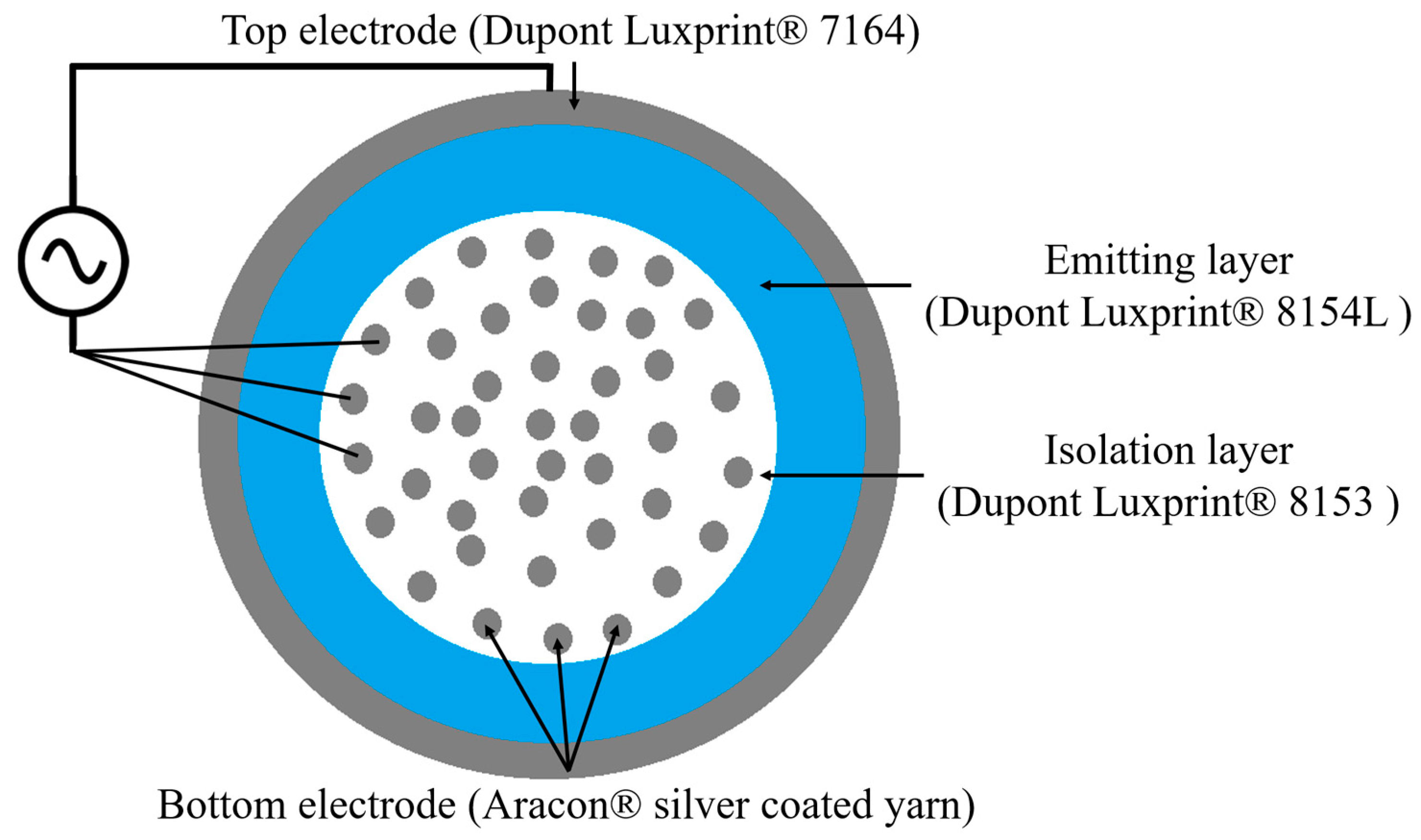
Electroluminescent (EL) fibers were fabricated by coating an alternating current phosphor-based EL (ACPEL) structure onto a supporting conductive fiber. The cross-sectional ACPEL device structure, depicted in Figure 1, consisted of a conductive bottom electrode, an isolation layer with a high dielectric constant to focus the electric field on the emitting layer and protect it from heating at this electrode, an emitting layer, and a top electrode layer that was translucent to allow light through. The Dupont Luxprint® material system was used due to its robustness, simplicity of deposition, and ease of handling after curing. The solution-processed layers were deposited in the following order onto an Aracon® XS0400E-018 silver-coated Kevlar® yarn (manufactured by Micro-coax, Inc., Pottstown, PA, USA): Dupont Luxprint® 8153 dielectric paste, Dupont Luxprint® 8154L phosphor paste, and Dupont Luxprint® 7164 transparent conductive paste. Upon application of the first isolation layer, the dielectric paste filled the gaps between the individual silver coated fibers within the underlying conductive yarn, creating a monofilament onto which subsequent layers were deposited. The individual strands of the supporting conductive yarn were randomly dispersed in the dielectric coating layer.
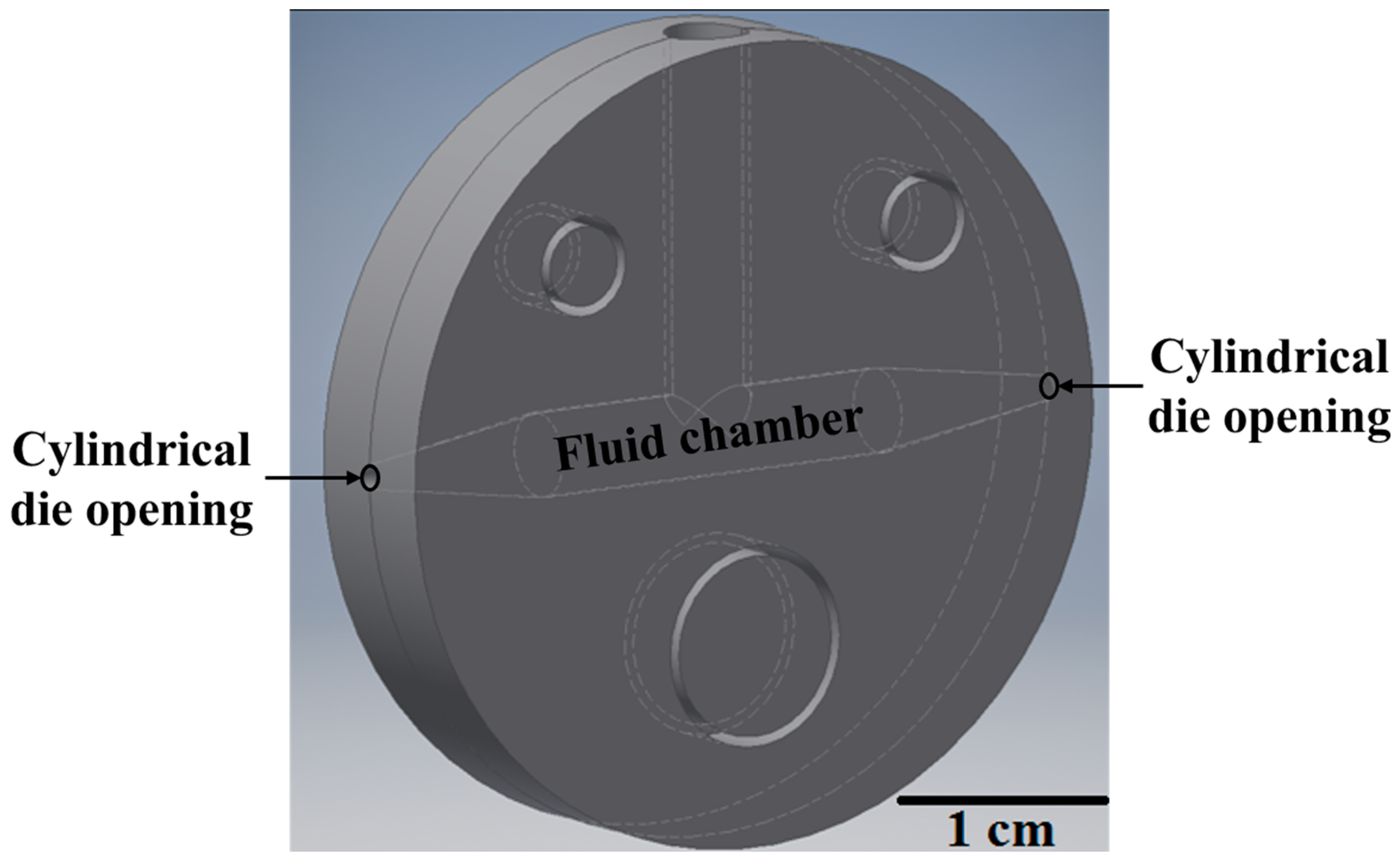
Slot die devices, like that shown in Figure 2, with varying cylindrical die openings were used to control the deposition of each layer onto the previous layer of the device structure. These devices were described in detail in previous work [29]. The fibers were cured inside an oven to evaporate the solvent from the fluid coating material after deposition. The dielectric and phosphor pastes were cured at 130 °C for 15 min, while the translucent conductive paste took only 5 min to cure at the same temperature [30]. Unlike many other organic and polymer emissive systems [24], this material set is not highly sensitive to surface roughness, oxygen, and particulates from the air due to its thick layers. Therefore, the entire fabrication process can take place in air and outside a clean room, which is a great advantage for scaling production of the fibers and using them in commercial applications.
2.2. Power Application and Fabric Integration
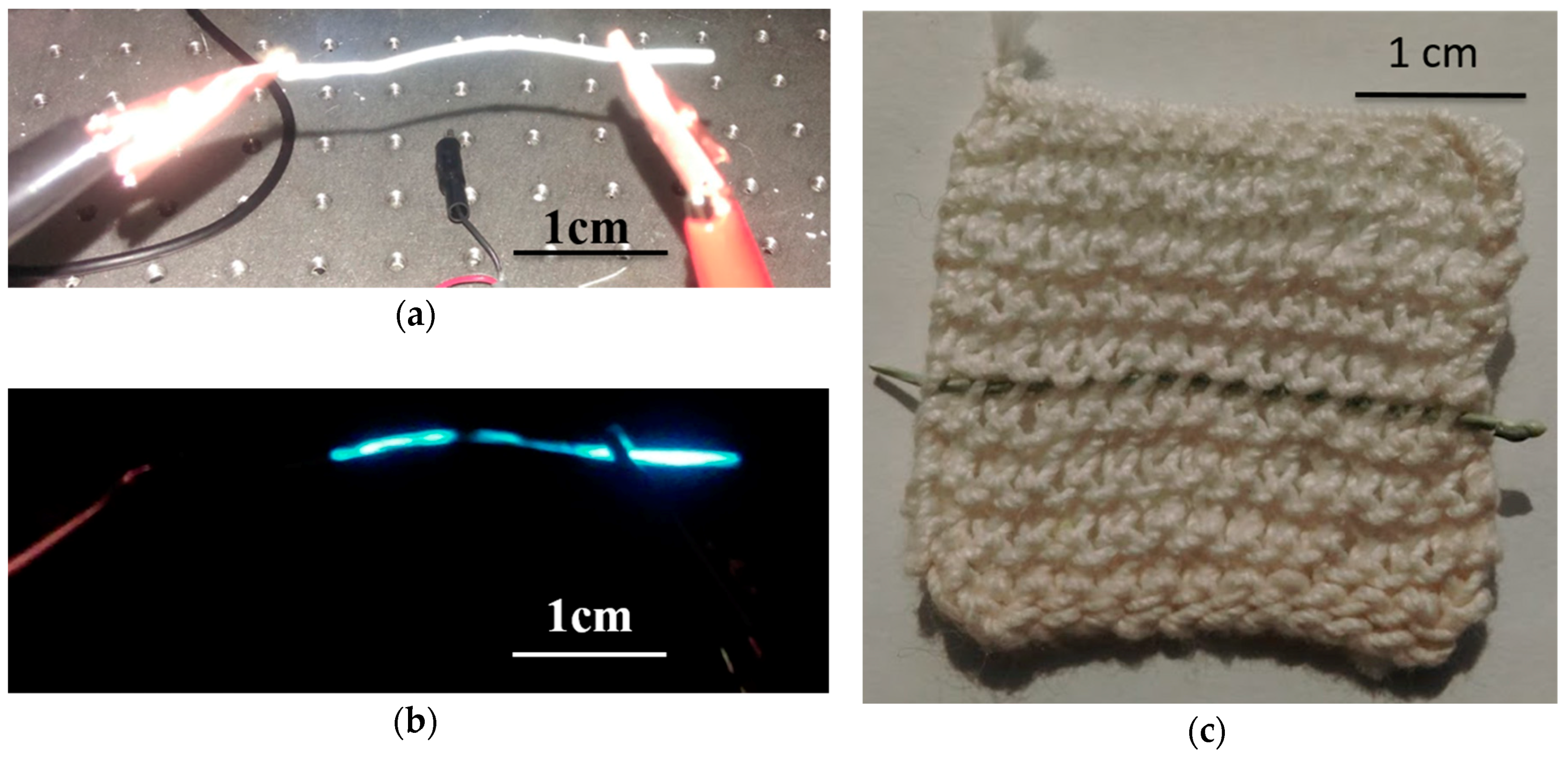
An Agilent 33220A arbitrary waveform generator (AWG) amplified by a TREK model PZD700 high voltage amplifier supplied power to the fibers. Power was applied between the top electrode and across all individual fibers of the supporting conductive yarn electrode simultaneously to illuminate the fiber. This was accomplished by twisting the individual fibers of the supporting conductive yarn together and contacting them using flat alligator clips as shown in Figure 3a. The more tightly packed the individual fibers of the supporting yarn electrode, the more efficient the devices because there is less power lost to the dielectric isolation layer. However, as long as the average isolation layer thickness between the emissive layer and conductive fibers of the supporting yarn closest to that emissive layer has a 35 ± 10 μm tolerance, light emission across the yarn will appear uniform to an observer. This thickness is controlled by the diameter of the cylindrical opening of the slot die coating device.
The illuminated fiber in Figure 3b had non-uniform emission due to an uneven dispersion of supporting conductive fibers. The thicknesses of the layers has been reported in previous work [29]. Although the total thickness of the isolation layer was consistent across, the parts of the fiber that appear dark had an isolation layer thickness between the emissive layer and conductive fibers of the supporting yarn greater than 50 μm. These dark areas were eliminated by keeping the fibers of the supporting yarn tightly twisted using clamps during deposition and curing to control the dispersion of the fibers in the isolation layer.
A 3 cm × 3 cm weft knit fabric composed of a 3-ply cotton yarn (Size 10 crochet cotton thread, Coats & Clark, Inc., Charlotte, NC, USA) with a gauge of 4 rows and 3 stitches = 1 cm was hand knit. A single fiber was inlaid into the fabric as shown in Figure 3c. The conductive ends of the fibers were accessible on either end of the fabric sample, which allowed power to be applied using flat alligator clips.
2.3. Optical Characterization Methods
Electrical, optical, mechanical tests were performed on EL fibers inside and outside of the cotton knit matrix. For each test, a 3-cm segment of fiber was tested due to space constraints in the fabrication and testing set ups. However, using a longer continuous segment of fiber or multiple fibers would increase the light output and effect the mechanical strength and flexibility of the light-emitting fabric.
Optical testing was performed inside a 12-inch diameter Gamma Scientific integrating sphere to eliminate any geometric and ambient light effects on the intensity of light. The intensity of the emitted light was measured by an Ocean Optics USB-4000 spectrometer attached via fiber optic cable to the integrating sphere and Spectrasuite software was used to process the data. Prior to beginning each optical measurement, a voltage waveform with amplitude below the threshold voltage of the device was applied to the fiber for half an hour to allow the device to reach the steady-state.
The voltage, frequency, and shape of the applied waveform can affect the optical output of the device. ACPEL devices are most efficient during the rising edge portion of the applied waveform, and least efficient when the voltage is held constant above the threshold voltage. A sine wave was used to illuminate the ACPEL fiber devices except for the device efficiency measurements. The threshold voltage of the EL fiber device was 49.833 V, which is independent of frequency. This voltage is the magnitude of power necessary to accelerate electrons inside the EL layer to speeds high enough to produce light via impact ionization with phosphor particles in the emitting layer.
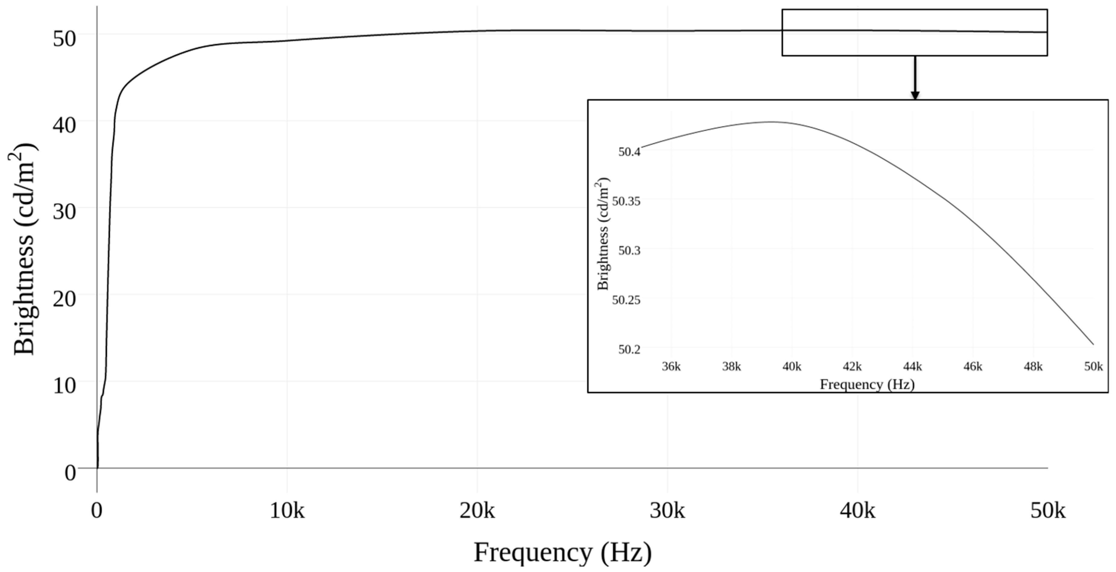
The frequency of the applied waveform plays a large role in the brightness of light emission in inorganic phosphor devices. The field must switch fast enough to have continuous excitation and decay of electrons, but cannot exceed the lifetime of electrons. The brightness-frequency (B-F) curve was determined by applying waveforms with increasing frequency to the device, while keeping the amplitude constant, and measuring the luminance at each increased frequency. The frequency was increased in increments of 100 Hz from 0 Hz to 50 kHz, while the voltage remained constant at 100 V. A constant voltage of 100 V was selected for the frequency sweep as it is in the middle of the fiber operating range. The brightness-voltage (B-V) curve was determined by applying waveforms with increasing amplitude (higher voltage) at a constant frequency of 400 Hz to the device and measuring the luminance at each successive amplitude. The voltage sweep was performed on fibers at a constant frequency of 400 Hz, while the voltage was increased in increments of 10 V from 0 V to 230 V. To determine if the knitted matrix absorbed or blocked any light from the fibers, voltage and frequency sweeps were performed on fibers inlaid into and outside a knitted fabric matrix.
2.4. Device Efficiency Calculation
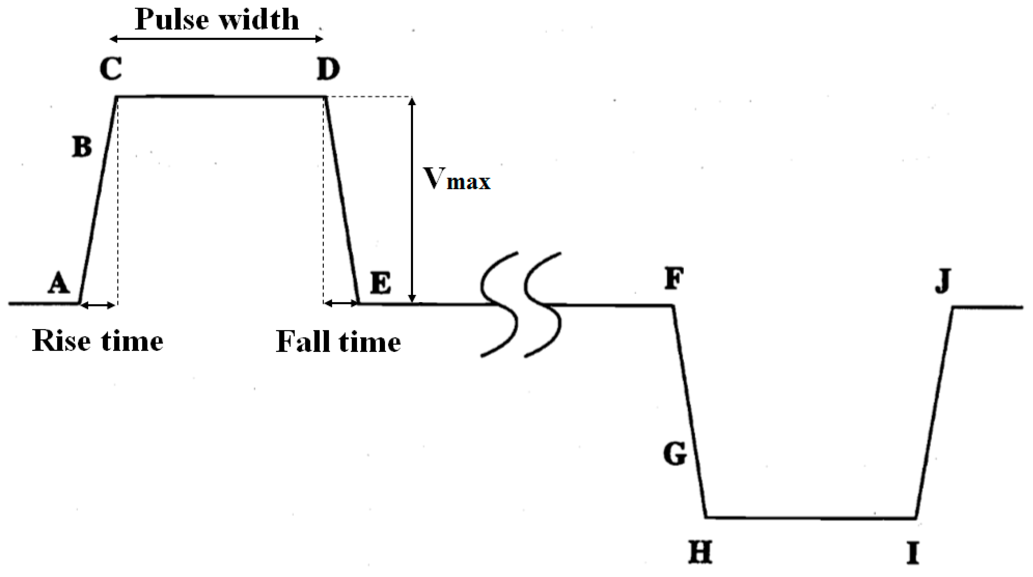
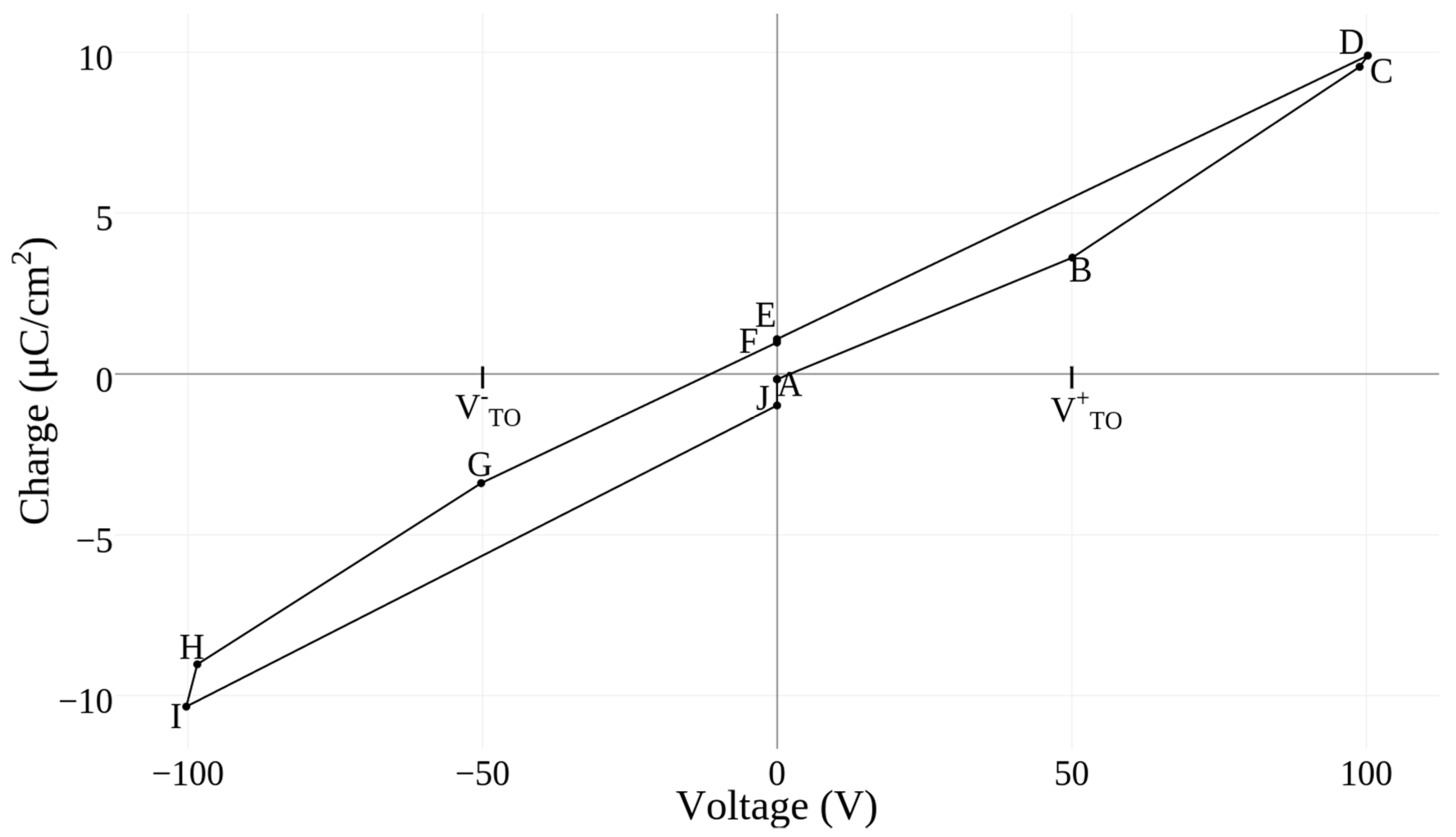
A bipolar trapezoidal waveform, shown in Figure 4, was used to drive the fiber in the circuit as there are distinct points on the waveform that can be identified and plotted to obtain a Q-V curve. These points have been explained in great detail in prior work [25,31]. Most of the points designated where the applied voltage began increasing and decreasing, except for B and G, which represent the points in the waveform where the device began conducting charge, commonly called the turn-on voltage.
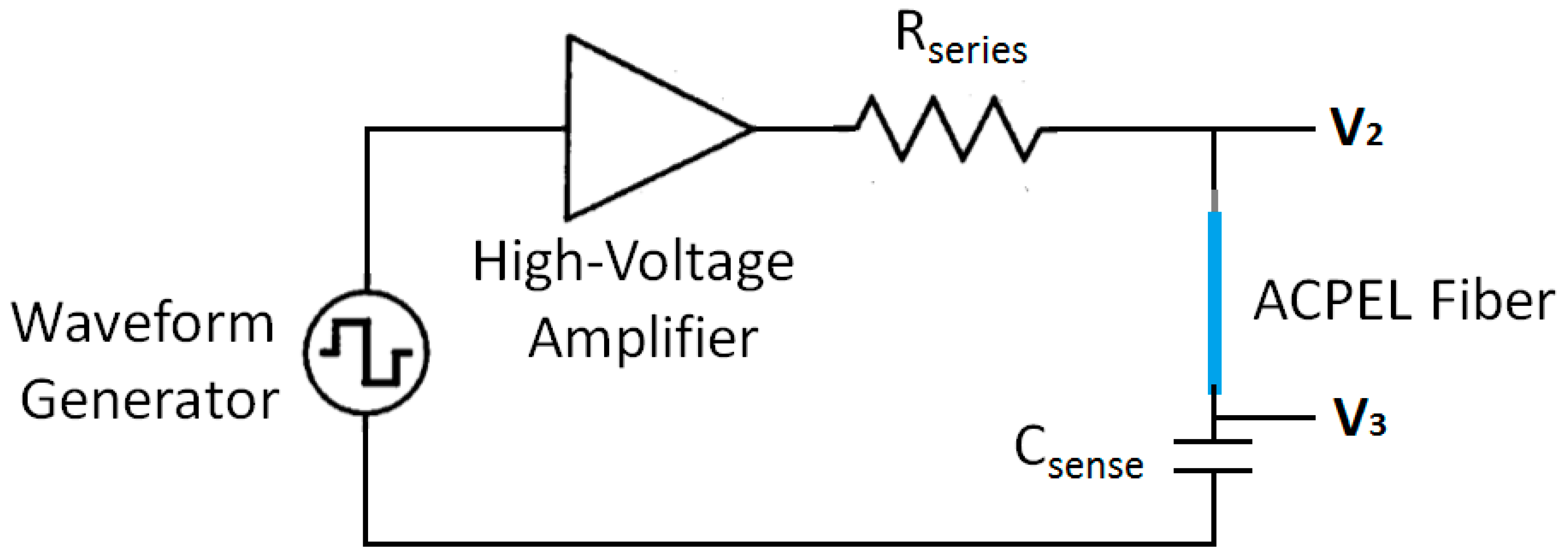
The device efficiency can be derived from the charge-voltage (Q-V) curve of the ACPEL fibers. The density of electrical power delivered across the ACPEL device per pulse is equal to the area inside the Q-V curve. This measurement divided by the input power equals the device efficiency. The Sawyer-Tower method is commonly used to determine this curve in EL devices [32,33]. In this method, the voltage drop across a sense element, typically a capacitor or resistor, is monitored to gain information about device operation. The Sawyer-Tower circuit is depicted in Figure 5. The signal applied to the circuit consisted of a 1 kHz sequence of bipolar pulses with 100 V amplitude, rise, and fall times of 5 µs and a pulse width of 30 µs.
The output of the high-voltage amplifier drives the characterization circuit, which is a series combination of a resistor, the ACPEL fiber device, and a sense element. The sense element in this case was a capacitor, which was chosen to be much larger than the capacitance of the ACTFEL device to minimize its effect on the measurement. The resistor acts as a current-limiter to protect the ACPEL fiber device from catastrophic failure. The capacitance of a pixel in the 3 cm segment of ACPEL fiber was measured with a GW Instek LCR-819 LCR meter as 0.27 nF, so an 82 nF capacitor was used as the sense element (Csense) in the characterization circuit. The resistor acts as a current-limiter to protect the ACPEL fiber device from catastrophic failure, so a 1.5 kΩ resistor was used. The voltages V2 and V3 in Figure 6 and Figure 7 were monitored by an Agilent MSO-X 2014A oscilloscope during testing.
The voltage drop across the sense capacitor, V3(t), is related to the amount of charge stored on the external terminals of the ACPEL fiber device, qext(t), and described by
The value of qext(t) is also called the instantaneous external charge because it is a transient charge measured externally with respect to the phosphor of the ACPEL device. The Q-V characteristics are obtained by plotting this instantaneous electric charge against the instantaneous voltage drop across the ACPEL fiber device, Vi(t), which is determined by
2.5. Mechanical Characterization Methods
The force vs. displacement curves of the EL fibers inside and outside of the knitted matrix and the bending radius of the fibers were previously reported [34] and demonstrated that the fibers were not flexible enough to be used in garments. To further explain the effect in both the knitted fabric and EL fiber after integration and determine what applications the fibers can be used for, flexural stress-strain curves were derived from the three-point flexural test detailed by ASTM D6856/D6856M [35,36]. Experimental tests were performed with a Mark-10 Force Gauge model MS-20 on fibers inside and outside of a fabric matrix. Details of this testing set up are given in a previous work [34].
Equations (3) and (4) are based on homogeneous beam theory and define the flexural stress for a circular cross section (σf) and flexural strain (εf) on the outer surface of the fiber, respectively [36]. In these equations, F is applied load, L is the support span, R is the radius of the fiber, D is the deflection of the fiber, and d is the diameter of the beam [37].
These equations were used to calculate the flexural stress-strain response of fibers inside and outside of the knit fabric as an increasing load was applied. The three-point bend test method is sensitive to the geometry of the fiber, and the accuracy of the calculated values depends upon the ratio of the beam length (L) to the cross-sectional height of the fiber (h), called the span to thickness ratio (L/h). A L/h ratio of at least 20:1 is recommended for determining the flexural modulus of fiber-reinforced composites [36]. During experimentation, the L/h ratio was 32:1, which is in the recommended range of values for determining the flexural modulus according to ASTM D6856/D6856M.28 [35].
3. Results
3.1. Optical Characterization
Figure 6 shows the results of the frequency sweep. The intensity of light increased with increasing frequency until approximately 45 kHz, when darkening at the center began to appear and the overall intensity decreased. This darkening was a result of the increase in degradation of the electroluminescent devices under very high frequencies. There is minimal gain in luminance with a frequency above 5 kHz and continuous operation of the fiber devices at higher frequencies will decrease the lifetime of the fiber, so it is better to run the device at frequencies below this point [30].
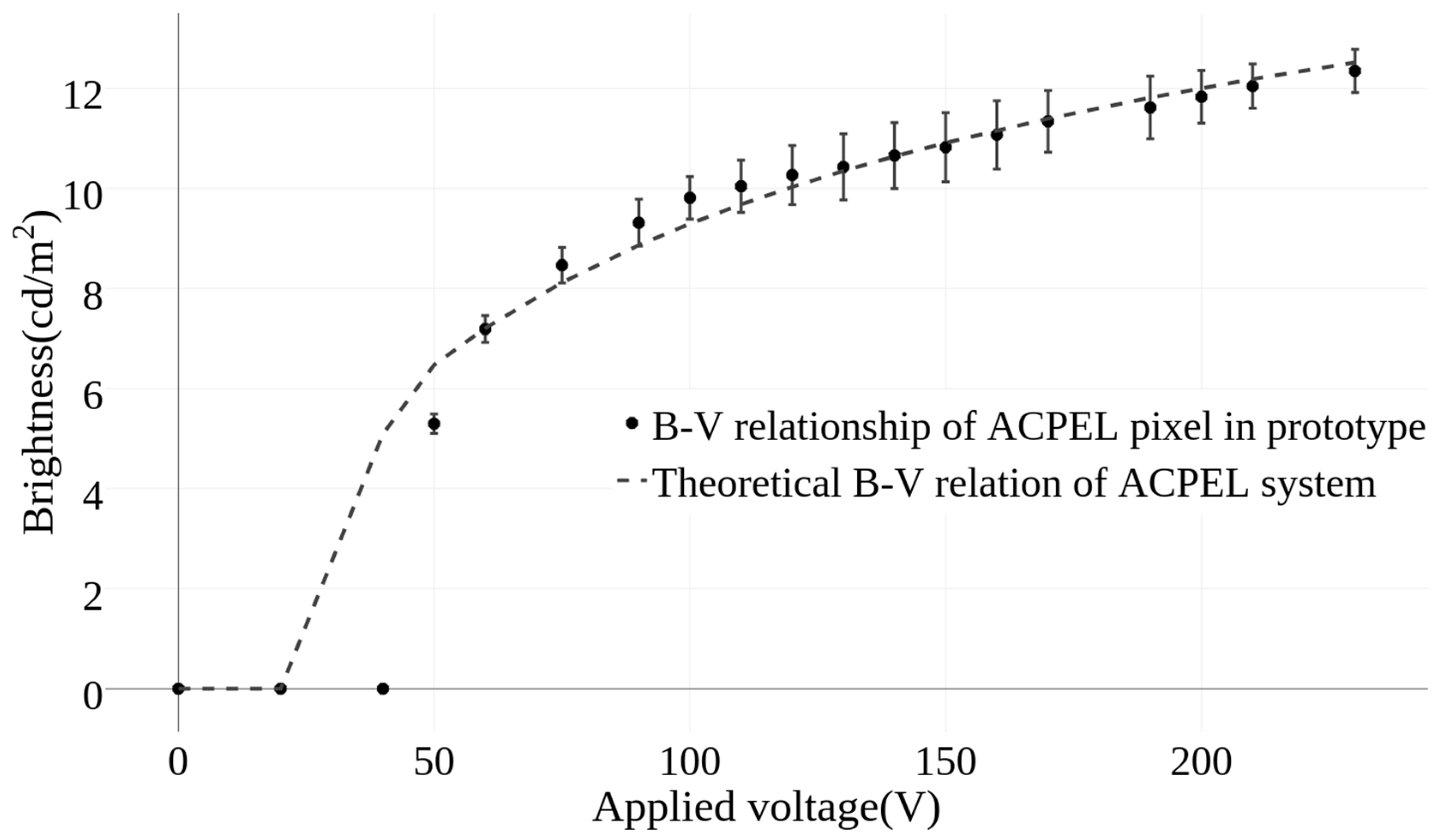
The relationship between brightness and voltage is well defined in the literature for ACPEL material systems and is described by Equation (5), where U is the applied voltage and A and c are empirical constants [38,39]. These empirical constants are dependent on the material properties of the ACPEL system, and are unique to the material under investigation. Once the empirical constant has been derived, the brightness of the fiber at different voltages can be theoretically predicted for this fiber. Alternatively, one can predict what voltage would be needed to achieve a desired brightness from the material and determine if these fibers will fit into an application based on the limitations of the device.
The empirical constants of the ACPEL material system used in this work were derived using a nonlinear regression analysis to fit the equation to the average of five experimental voltage sweeps performed on a single pixel in the display. Figure 7 demonstrates the accuracy of the brightness-voltage (B-V) curve predicted by Equation (5), where the empirical constants A and c for this ACPEL system were calculated as 22.2678 and 8.7396, respectively. The error bars at each voltage increment of the experimentally derived curve show the standard deviation to the average of the five voltage sweeps performed on the pixel. The difference in luminance of a fiber inside and outside of a knitted fabric matrix was measured as 0.00015 ± 0.00005 cd/m2 regardless of the voltage or frequency applied.
3.2. Device Efficiency
Figure 8 depicts the Q-V curve of an EL fiber at 100 V. The density of power delivered to the device per pulse was 323.64 W/cm3. The power efficiency of the device could then be derived by dividing this delivered power by the input power, which gave an efficiency of 0.016% for this device at 40 V above threshold. This efficiency depends upon a number of factors including the concentration of phosphor particles in the emitting layer, applied waveform, length of the fiber, environmental factors, and the dielectric constant of both the isolation layer and suspension medium of the emitting layer [31]. Thus, the efficiency of the device can vary over time and under different operating conditions.
3.3. Mechanical Characterization
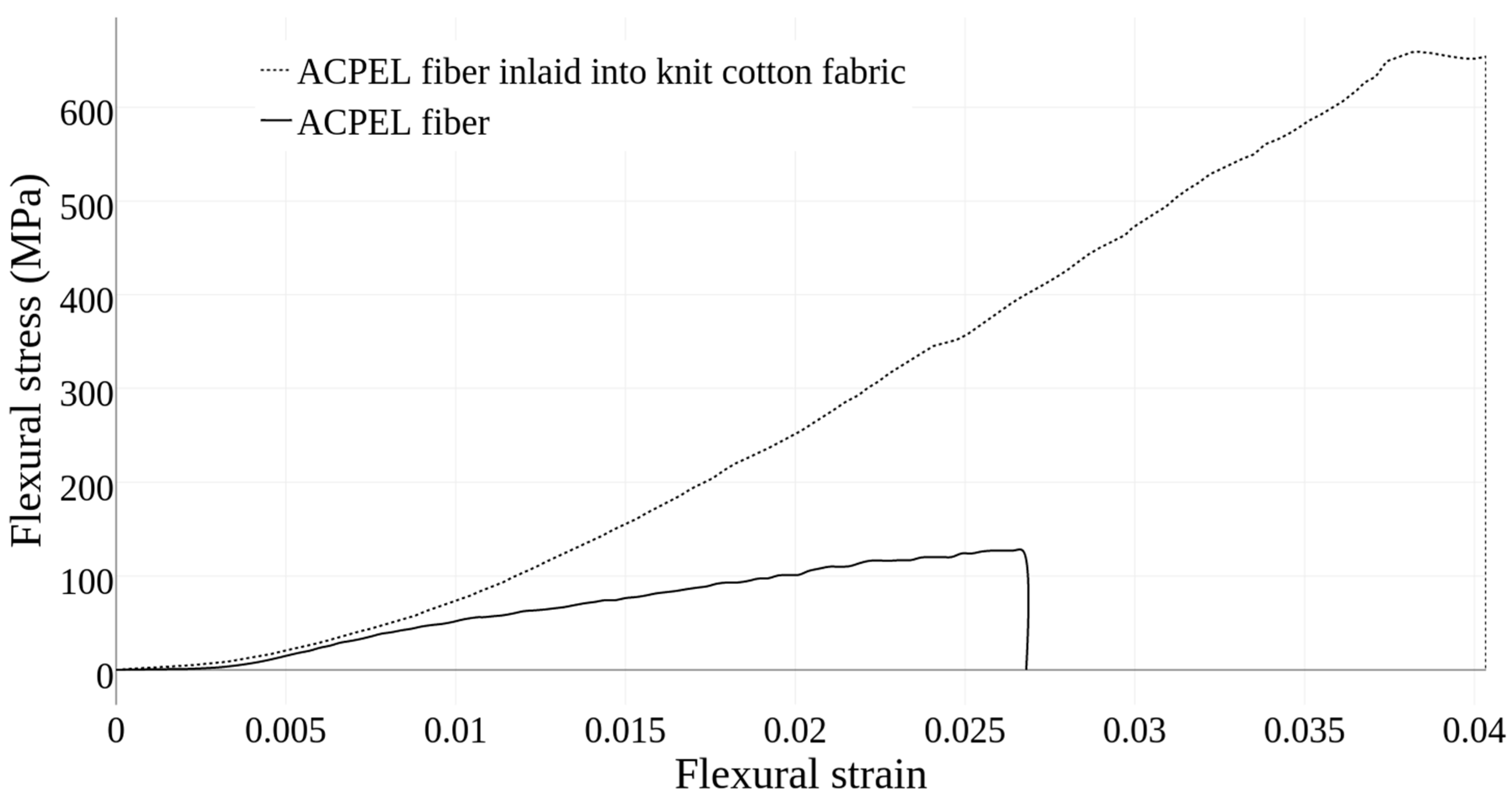
The curves resulting from the mechanical tests, shown in Figure 9, indicated that the knitted matrix absorbed some of the applied stress and allowed the inlaid fiber to withstand a much higher load than the fiber on its own. The flexural strength is a measure of how much force or pressure is needed to break the fibers, which is quantified by the maximum stress before fiber failure. Assuming that the maximum stress occurs at the outermost layer in the EL fiber, the flexural strength can be calculated by Equation (3), where F is the maximum force applied before failure [40]. The flexural strength of the fibers inside and outside the knitted matrix was calculated as 5.23 MPa and 2.02 MPa, respectively. Based on these values, the knitted matrix allows the fiber to withstand more than twice the load that it would be able to on its own.
The flexural modulus of the fibers is the ratio of stress to strain in flexural deformation, which describes the material’s tendency to bend. The higher the flexural modulus, the more resistant it is to bending. Ideally, this flexural modulus is equivalent to the elastic modulus of the material, but in reality, these values may differ due to the presence of normal and shear stresses throughout the beam span. The contribution of the shear stress can be reduced by using a high L/h ratio. During experimentation, a sufficiently high L/h ratio was maintained to minimize this effect. The flexural modulus of an EL fiber outside the knit textile was determined using Equation (6), where m is the initial slope of the load-deflection curve given in Figure 9 [41].
The flexural modulus of a single fiber was determined to be 4.9 GPa, which means that these fibers are stiff and have a high resistance to bending.
4. Discussion
The frequency has a more pronounced effect on the brightness of the ACPEL system than the voltage because of the time dependence of light emission in ACPEL devices. Upon application of an electric field with a high enough magnitude, electrons are excited by impact ionization and emit light as they relax back to ground state. This relaxation process occurs on the order of nanoseconds, and the emission produced has an equivalent decay time. To have a continuous emission, the applied field must be constantly switched as the emission and subsequent decay of the devices occurs twice per AC cycle. Generally, a higher frequency will result in a higher brightness due to the time dependence of the emission [28]. However, once the AC cycle becomes comparable to or surpasses the lifetime of excited electrons, the brightness will decrease.
A number of textile properties such as gauge, yarn thickness, and yarn material could affect the visible light output of the fibers. Specifically, a tighter gauge, thicker yarn, or denser yarn material could decrease the amount of visible light. The apparent brightness of the fibers will also change based on the amount of ambient light. In applications where the surroundings are dark, like a wall mounted screen in a movie theater or night time concert, the fibers could be run at lower voltages and frequencies, thus increasing the lifetime of the device.
The efficiency of the fiber is an internal property of the fiber that will not change with fabric integration. However, the wear and tear that the fiber experiences during normal use in a functional fabric will decrease this efficiency over time. The efficiency is an important property of the fiber as it determines the power requirements of the fiber. The low device efficiency exhibited by the ACPEL fibers is a consequence of the indirect method of light emission in these devices, which gives rise to high power requirements. However, this AC power can be supplied directly in airplanes and through wall electrical outlets, enabling automotive interior lighting and wall-mounted lighting applications.
Moisture, and therefore humidity, can accelerate the natural decrease in luminous efficiency that occurs over time in inorganic phosphor devices [42]. The transparent conductive top layer reduces the exposure of the phosphor layer to such environmental effects. However, fabrics incorporating these fibers should not be subjected to excessive moisture like soaking or washing without additional precautions to protect the fibers. Additionally, the high power requirements significantly reduce the portability of the fibers and fabrics supporting these fibers and require that the fibers be isolated from human skin. In the future, an encapsulation layer could be added to protect the fibers and electrically isolate them to prevent human contact. However, the addition of more layers could further reduce the flexibility of the fibers, so a highly flexible polymer encapsulation layer is recommended.
The ACPEL fibers exhibit a high resistance to bending, which has been discussed in previous work [29,34]. Thus, when introduced into the knitted matrix, they reduced the overall flexibility, but significantly increased the strength of the fabric. This increased strength results from the distribution of force across the fiber and matrix. The fiber absorbs some of the force and as it has a high flexural strength, it reinforces the fabric strength. This increased strength is useful in applications where the fibers is subjected to a great deal of perpendicular stresses such as automotive carpet lighting or a display screen directly integrated into the fabric of a car seat.
5. Conclusions
In this paper, ACPEL fiber devices were fabricated and experimentally analyzed. To demonstrate the performance and potential of these fibers in functional fabrics, electrical, optical, and mechanical tests were performed on the fibers inside and outside of a knit fabric. The simple fabrication procedures and ease of handling streamlines the integration of ACPEL fibers into knitted fabrics. The integration of ACPEL fibers into a knit structure improves the strength and robustness of the resulting light emitting fabric, making it useful for applications in automotive/airplane interior lighting and emissive wall displays.
Author Contributions
A.M. fabricated the EL devices, performed the characterization experiments, analyzed the data and wrote the paper. A.F. contributed all other materials/analysis tools and revised the manuscript.
Funding
This material is based upon work supported by both the National Science Foundation Graduate Research Fellowship under Grant No. DGE-1104459, and the National Science Foundation STEM K-12 Fellowship under grant No. DGE-0947936.
Conflicts of Interest
The authors declare no conflict of interest.
References
- Dalsgaard, C.; Sterrett, R. White paper on smart textile garments and devices: A market overview of smart textile wearable technologies. In Market Opportunities for Smart Textiles; Ohmatex: Viby, Denmark, 2014. [Google Scholar]
- Janietz, S.; Gruber, B.; Schattauer, S.; Schulze, K. Integration of OLEDs in textiles. Adv. Sci. Technol. 2013, 80, 14–21. [Google Scholar] [CrossRef]
- Wang, G.F.; Tao, X.M.; Huang, H.M. Light-emitting devices for wearable flexible displays. Color. Technol. 2005, 121, 132–138. [Google Scholar] [CrossRef]
- Orth, M.; Post, R.; Cooper, E. Fabric computing interfaces. In CHI 98 Conference Summary on Human Factors in Computing Systems—CHI ’98; ACM Press: New York, NY, USA, 1998; pp. 331–332. [Google Scholar] [Green Version]
- CuteCircuit. Available online: https://cutecircuit.com/ (accessed on 8 July 2016).
- Mauriello, M.; Gubbels, M.; Froehlich, J. Social fabric fitness: The design and evaluation of wearable E-textile displays to support group running. In Proceedings of the SIGCHI Conference on Human Factors in Computing Systems, Toronto, ON, Canada, 26 April–1 May 2014. [Google Scholar]
- Jost, K.; Stenger, D.; Perez, C.R.; McDonough, J.K.; Lian, K.; Gogotsi, Y.; Dion, G. Knitted and screen printed carbon-fiber supercapacitors for applications in wearable electronics. Energy Environ. Sci. 2013, 6, 2698–2705. [Google Scholar] [CrossRef]
- Koncar, V. Optical fiber fabric displays. Opt. Photonics News 2005, 16, 40–44. [Google Scholar] [CrossRef]
- Spigulis, J. Side-emitting fibers brighten our world. Opt. Photonics News 2005, 16, 34–39. [Google Scholar] [CrossRef]
- Deflin, E.; Koncar, V.; Weill, A.; Vinchon, H. Bright optical fiber fabric: A new flexible display. Text. Asia 2001, 33, 25–28. [Google Scholar]
- Jeong, S.M.; Song, S.; Seo, H.-J.; Choi, W.M.; Hwang, S.-H.; Lee, S.G.; Lim, S.K. Battery-Free, Human-Motion-Powered Light-Emitting Fabric: Mechanoluminescent Textile. Adv. Sustain. Syst. 2017, 1, 1700126. [Google Scholar] [CrossRef]
- Zhang, Z.; Guo, K.; Li, Y.; Li, X.; Guan, G.; Li, H.; Luo, Y.; Zhao, F.; Zhang, Q.; Wei, B.; et al. A colour-tunable, weavable fibre-shaped polymer light-emitting electrochemical cell. Nature 2015, 9, 233–238. [Google Scholar] [CrossRef]
- Yang, H.; Lightner, C.R.; Dong, L. Light-emitting coaxial nanofibers. ACS Nano 2012, 6, 622–628. [Google Scholar] [CrossRef] [PubMed]
- Samei, E.; Badano, A.; Chakraborty, D.; Compton, K.; Cornelius, C.; Corrigan, K.; Flynn, M.J.; Hemminger, B.; Hangiandreou, N.; Johnson, J.; et al. Assessment of display performance for medical imaging systems. Med. Phys. 2005, 32, 1205–1225. [Google Scholar] [CrossRef] [PubMed]
- O’Connor, B.; An, K.K.H.H.; Zhao, Y.; Pipe, K.P.P.K.; Shtein, M. Fiber Shaped Light Emitting Device. Adv. Mater. 2007, 19, 3897–3900. [Google Scholar] [CrossRef]
- Kwon, S.; Kim, W.; Kim, H.C.; Choi, S.; Park, B.-C.; Kang, S.-H.; Choi, K.C. P-148: Polymer Light-Emitting Diodes Using the Dip Coating Method on Flexible Fiber Substrates for Wearable Displays. In Proceedings of the 53rd Annual SID Symposium, San Jose, CA, USA, 21 May–5 June 2015; Volume 46, pp. 1753–1755. [Google Scholar]
- Dias, T.; Monaragala, R. Development and analysis of novel electroluminescent yarns and fabrics for localized automotive interior illumination. Text. Res. J. 2012, 82, 1164–1176. [Google Scholar] [CrossRef]
- Coyle, J.P.; Li, B.; Dion, G.; Fontecchio, A.K. Direct integration of a 4-pixel emissive display into a knit fabric matrix. Adv. Disp. Technol. III 2013, 8643, 864308. [Google Scholar] [CrossRef]
- Zhang, Z.; Cui, L.; Shi, X.; Tian, X.; Wang, D.; Gu, C.; Chen, E.; Cheng, X.; Xu, Y.; Hu, Y.; et al. Textile Display for Electronic and Brain-Interfaced Communications. Adv. Mater. 2018, 30, 1800323. [Google Scholar] [CrossRef] [PubMed]
- Services, S.A.T. Glow Yarns for Special Effects in Textiles from Swicofil. Available online: http://www.swicofil.com/glow_yarn.html (accessed on 23 June 2017).
- Bortz, T.; Agrawal, S.; Shelnut, J. Photoluminescent Fibers, Compositions and Fabrics Made Therefrom. U.S. Patent 8,207,511, 26 June 2012. [Google Scholar]
- Gauvreau, B.; Guo, N.; Schicker, K.; Stoeffler, K.; Boismenu, F.; Ajji, A.; Wingfield, R.; Dubois, C.; Skorobogatiy, M. Color-changing and color-tunable photonic bandgap fiber textiles. Opt. Express 2008, 16, 15677–15693. [Google Scholar] [CrossRef] [PubMed]
- Sayed, I.; Berzowska, J.; Skorobogatiy, M. Jacquard-woven photonic bandgap fiber displays. Res. J. Text. Appar. 2010, 14, 97–105. [Google Scholar] [CrossRef]
- O’Connor, B.; Pipe, K.; Shtein, M. Fiber based organic photovoltaic devices. Appl. Phys. Lett. 2008, 92, 172. [Google Scholar] [CrossRef]
- Bellingham, A. Direct Integration of Dynamic Emissive Displays into Knitted Fabric Structures; Drexel University: Philadelphia, PA, USA, 2017. [Google Scholar]
- Kim, W.; Kwon, S.; Lee, S.-M.; Kim, J.Y.; Han, Y.; Kim, E.; Choi, K.C.; Park, S.; Park, B.-C. Soft fabric-based flexible organic light-emitting diodes. Org. Electron. 2013, 14, 3007–3013. [Google Scholar] [CrossRef]
- Kwon, S.; Kim, W.; Kim, H.; Choi, S.; Park, B.-C.; Kang, S.-H.; Choi, K.C. High Luminance Fiber-Based Polymer Light-Emitting Devices by a Dip-Coating Method. Adv. Electron. Mater. 2015, 1, 1500103. [Google Scholar] [CrossRef]
- Bredol, M.; Dieckhoff, H.S. Materials for Powder-Based AC-Electroluminescence. Materials 2010, 3, 1353–1374. [Google Scholar] [CrossRef] [Green Version]
- Bellingham, A.; Bromhead, N.; Fontecchio, A. Rapid Prototyping of Slot Die Devices for Roll to Roll Production of EL Fibers. Materials 2017, 10, 594. [Google Scholar] [CrossRef] [PubMed]
- Dupont. Processing Guide for DuPont Luxprint Electroluminescent Inks. 2012. Available online: http://www.dupont.com/content/dam/dupont/products-and-services/electronic-and-electricalmaterials/documents/prodlib/MCM-EL-Processing-Guide.pdf (accessed on 16 July 2018).
- Keir, P. Fabrication and Characterization of ACTFEL Devices, Oregon State. 1999. Available online: https://ir.library.oregonstate.edu/concern/graduate_thesis_or_dissertations/n009w490c (accessed on 16 July 2018).
- Aleksandrova, M.P.; Dobrikov, G.H.; Andreev, S.K.; Dobrikov, G.M.; Rassovska, M.M. Electrical Properties Characterization of Thick Film Organic Electroluminescent Structures. Annu. J. Electron. 2011, 5, 183–186. [Google Scholar]
- Wager, J.F.; Keir, P.D. Electrical Characterization of thin-film electroluminescent devices. Annu. Rev. Mater. Sci. 1997, 27, 223–248. [Google Scholar] [CrossRef]
- Bellingham, A.; Fontecchio, A. Direct integration of individually controlled emissive pixels into knit fabric for fabric-based dynamic display. IEEE Photonics J. 2017, 9, 1–10. [Google Scholar] [CrossRef]
- Standard Guide for Testing Fabric-Reinforced Textile Composite Materials. ASTM International: West Conshohocken, PA, USA. Available online: http://www.astm.org/cgi-bin/resolver.cgi?D6856D6856M (accessed on 16 July 2018).
- Zweben, C.; Smith, W.; Wardle, M. Test methods for fiber tensile strength, composite flexural modulus, and properties of fabric-reinforced laminates. In Composite Materials: Testing and Design (Fifth Conference); ASTM International: West Conshohocken, PA, USA, 1979. [Google Scholar]
- Oberg, E.; Jones, F.; Horton, H.; Ryffel, H. Machinery’s Handbook; Industrial Press: New York, NY, USA, 2004. [Google Scholar]
- Zalm, P.; Diemer, G.; Klasens, H. Some aspects of the voltage and frequency dependence of electroluminescent zinc sulphide. Philips Res. Rep. 1955, 10, 205–215. [Google Scholar]
- Alfrey, G.F.; Taylor, J.B. Electroluminescence in Single Crystals of Zinc Sulphide. Proc. Phys. Soc. Sect. B 1955, 68, 775–784. [Google Scholar] [CrossRef]
- Hodgkinson, J.M. Mechanical Testing of Advanced Fibre Composites; Elsevier: New York, NY, USA, 2000; ISBN 9781855738911. [Google Scholar]
- Mallick, P.K. Fiber-Reinforced Composites: Materials, Manufacturing, and Design; CRC/Taylor & Francis: Boca Raton, FL, USA, 2007; ISBN 1420005987. [Google Scholar]
- Smet, P.F.; Moreels, I.; Hens, Z.; Poelman, D. Luminescence in Sulfides: A Rich History and a Bright Future. Materials 2010, 3, 2834–2883. [Google Scholar] [CrossRef] [Green Version]
Figure 1.
Schematic diagrams of the ACPEL fiber structure.

Figure 2.
Model of slot die devices used to deposit ACPEL layers onto supporting yarn substrate [29].
Figure 2.
Model of slot die devices used to deposit ACPEL layers onto supporting yarn substrate [29].

Figure 3.
Macro images of the ACPEL fibers (a) outside of knit indicating where electrodes are connected to fiber during testing, (b) illuminated at 100 Vrms, 400 Hz, and (c) inlaid into 3 cm 2 knit fabric sample.
Figure 3.
Macro images of the ACPEL fibers (a) outside of knit indicating where electrodes are connected to fiber during testing, (b) illuminated at 100 Vrms, 400 Hz, and (c) inlaid into 3 cm 2 knit fabric sample.

Figure 4.
Bipolar trapezoid waveform indicating important measurement points.

Figure 5.
Schematic diagram of Sawyer-Tower measurement circuit set up.

Figure 6.
Effect of frequency on the luminance of the inlaid fiber (Voltage = 100 VAC).

Figure 7.
Comparison of the theoretically and experimentally derived relationship between brightness and voltage of an ACPEL fiber inside a knit fabric.
Figure 7.
Comparison of the theoretically and experimentally derived relationship between brightness and voltage of an ACPEL fiber inside a knit fabric.

Figure 8.
Charge-Voltage (Q-V) curve of the 3 cm ACPEL fiber at 100 V.

Figure 9.
Bipolar trapezoid waveform indicating important measurement points.


Table 1.
Comparison of electroluminescent fiber properties reported in literature.
| Type of Fiber | Wavelength | Maximum Emission Intensity | Turn On Voltage | Bending Radius | Reference |
|---|---|---|---|---|---|
| ACPEL | 485 nm | 49.39 cd/m2 | 50 V | 3.1 cm | [17,25] |
| LEC (iTMC) | 855–984 nm | 23 cd/m2 | 4.2 V | 6 mm | [13] |
| OLED | N/A | 104 mW/cm2 | ~0.5 V | N/A | [15] |
| pLEC | N/A | 125 cd/m2 | 4.2 V | N/A | [12] |
| PLED (MEH-PPV) | ~575 nm | N/A | 15–16 V | N/A | [18] |
| PLED (SY solution) | ~550 nm | 1458.8 cd/m2 | 5 V | 2.5 mm | [16] |
© 2018 by the authors. Licensee MDPI, Basel, Switzerland. This article is an open access article distributed under the terms and conditions of the Creative Commons Attribution (CC BY) license (http://creativecommons.org/licenses/by/4.0/).
Share and Cite
MDPI and ACS Style
Martin, A.; Fontecchio, A. Effect of Fabric Integration on the Physical and Optical Performance of Electroluminescent Fibers for Lighted Textile Applications. Fibers 2018, 6, 50. https://0-doi-org.brum.beds.ac.uk/10.3390/fib6030050
AMA Style
Martin A, Fontecchio A. Effect of Fabric Integration on the Physical and Optical Performance of Electroluminescent Fibers for Lighted Textile Applications. Fibers. 2018; 6(3):50. https://0-doi-org.brum.beds.ac.uk/10.3390/fib6030050
Chicago/Turabian StyleMartin, Alyssa, and Adam Fontecchio. 2018. "Effect of Fabric Integration on the Physical and Optical Performance of Electroluminescent Fibers for Lighted Textile Applications" Fibers 6, no. 3: 50. https://0-doi-org.brum.beds.ac.uk/10.3390/fib6030050
Note that from the first issue of 2016, this journal uses article numbers instead of page numbers. See further details here.