Damage Characterization of Nano-Interleaved CFRP under Static and Fatigue Loading
by
 ,
,
Mohamad Fotouhi
1,*, 
Cristiano Fragassa
2 ,
,
Sakineh Fotouhi
3,
Hamed Saghafi
4 and
Giangiacomo Minak
2
1
Department of Design and Mathematics, University of the West of England, BS16 1QY Bristol, UK
2
Department of Industrial Engineering, University of Bologna, Viale Risorgimento 2, 40136 Bologna, Italy
3
Mechanical Engineering Department, University of Tabriz, Tabriz 51666-14766, Iran
4
Department of Mechanical Engineering, Tafresh University, Tehran Road, Tafresh 79611-39518, Iran
*
Author to whom correspondence should be addressed.
Fibers 2019, 7(2), 13; https://0-doi-org.brum.beds.ac.uk/10.3390/fib7020013
Submission received: 28 November 2018
/
Revised: 16 January 2019
/
Accepted: 19 January 2019
/
Published: 28 January 2019
(This article belongs to the Special Issue Fiber Reinforced Inorganic-Based Composite Systems for Structural Applications)
Abstract
:The use of high strength-to-weight ratio-laminated fiber-reinforced composites is emerging in engineering sectors such as aerospace, marine and automotive to improve productivity. Nevertheless, delamination between the layers is a limiting factor for the wider application of laminated composites, as it reduces the stiffness and strengths of the structure. Previous studies have proven that ply interface nanofibrous fiber reinforcement has an effective influence on delamination resistance of laminated composite materials. This paper aims to investigate the effect of nanofiber ply interface reinforcement on mode I properties and failure responses when being subjected to static and fatigue loadings. For this purpose, virgin and nanomodified woven laminates were subjected to Double Cantilever Beam (DCB) experiments. Static and fatigue tests were performed in accordance with standards and the Acoustic Emissions (AE) were acquired during these tests. The results showed not only a 130% increase of delamination toughness for nanomodified specimens in the case of static loads, but also a relevant crack growth resistance in the case of fatigue loads. In addition, the AE permitted to relate these improvements to the different failure mechanisms occurring.
1. Introduction
Due to their high strength-to-weight ratio and stiffness, carbon fiber-reinforced polymer (CFRP) composites have many applications in different sectors, such as aerospace, superstructure of ships, automotive, civil engineering and even sports goods. CFRP composites are usually produced by stacking several sheets of prepregs together, followed by a thermal treatment in autoclave where the pressure allows for a high fiber volume fraction and low void content for maximum structural efficiency. Unlike the excellent in-plane properties of CFRP, they suffer from damage between the plies such as delamination or cracks, which happen mostly in the matrix areas. These phenomena have been explored in a large number of investigations in relation to the dynamic damage and to the fracture mechanisms of both fibers and resins. For instance, the following aspects were investigated: the effect of stitching on the strain energy release [1], the improvement on the fracture toughness of laminates by the use of dissolvable thermoplastic [2], the interlayer self-healing and toughening of composites using copolymer films [3], and the relevance of the three-dimensionality on the damage [4].
Thus, different methods, such as matrix toughening, stitching of the plies, and three-dimensional woven fabrics, have been used to prevent delamination [5,6,7,8]. Solutions aiming to improve the matrix toughening, in particular, have recently attracted a lot of attention at which delamination toughness increases by using toughened material layers during the manufacturing.
A large number of researches were also done on toughening laminated composites using nanofibers interleaving with the overall conclusion that nanofibers can bring significant benefits to the composite under certain conditions of resin–polymer compatibility, size and amount of interleave, and type of material [9,10,11]. In this term, recent observations showed that mode I fracture toughness of epoxy resin composites increased with the use of Nylon 66 nanofibers [12,13], both in static and fatigue loading conditions, if these fibers are treated in a defined condition such as appropriate selection of thickness of nanofibrous and curing temperature.
Strictly in line with these considerations, the present paper aimed to identify the failure mechanisms that emerge in Nylon 66 nanofibers-interleaved composites in the occurrence of static and fatigue loadings. With this scope, the Acoustic Emission (AE) was preferred as a method of investigation: this powerful technique was already applied in the past to monitor the AE signals generated from the failure mechanisms in fiber-reinforced composites [14,15,16,17,18,19,20,21,22]. An AE signal can be related to the liberation of the intrinsic energy generated during a damage mechanism of fibers. Analyzing the intensity, frequency and waveform of this emission, it is possible to successfully identify the damage type and investigate the failure evolution.
As a general result, this paper reports a good correlation between the mechanical data and recorded AE signals that were obtained from the experiments on CFRP interleaved with the Nylon 66 nanofibers under both static and fatigue mode I interlaminar loadings.
2. Materials and Methods
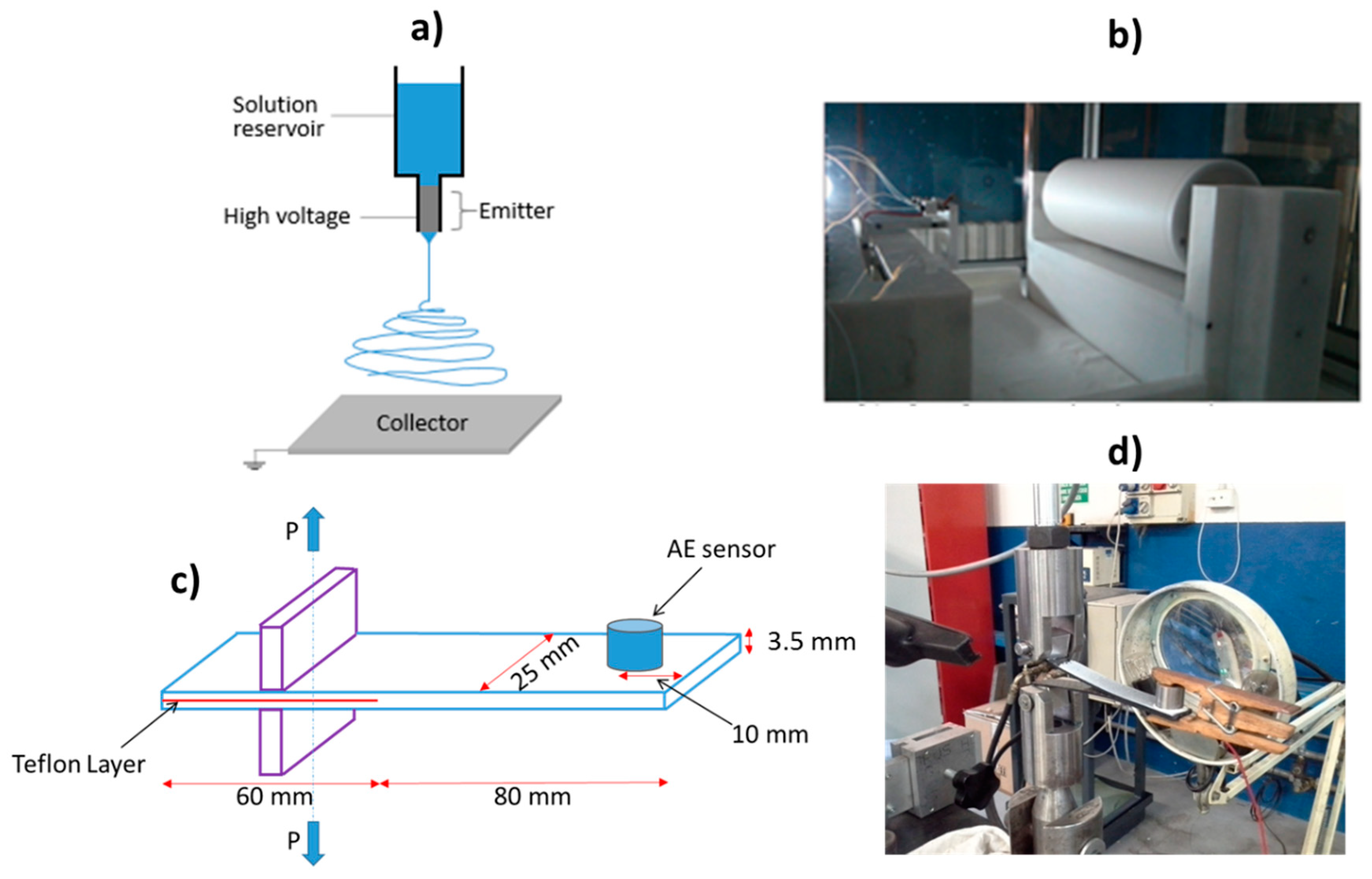
Two types of samples, virgin and nano-interleaved, were fabricated and tested. The samples were made from 14 plies of plain weave (PW) carbon–epoxy prepreg (GG204P-IMP503Z G. Angeloni Srl, Venice, Italy), with 220 g/m2, which were stacked together. The prepreg was supplied by Impregnatex Composite Srl (Milan, Italy). The virgin and nano-interleaved laminates were cut from two rectangular panels (300 × 170 mm2) that were cured in an autoclave at 60 °C cycle for 2 h and 130 °C cycle for 1 h, with 6 bar pressure, below Nylon’s melting temperature which is 260 °C. Later the rectangular plates were cut to the size of the test samples according to the ASTM D5528 standard [23], as illustrated in Figure 1. The only difference between the virgin and nano-interleaved samples was the addition of a Nylon 66 nanofiber mat between plies 7 and 8 in the nano-interleaved samples. This nanofiber mat had a 40 µm-thickness, 18 g/m2-areal density and 400–650 nm-diameter nanofibers. Electrospinning technology (see Figure 1a for the schematic) was used to fabricate the Nylon 66 nanofiber mats. Electrospun non-woven mats were fabricated using an in-house electrospinning apparatus (Figure 1a) composed of: (1) a high voltage power supply, (2) a syringe pump (200 series, KDScientific, Holliston, MA, USA), (3) four syringes (KDScientific), (4) four Teflon tubes, (5) four needles with a diameter of 0.6 mm, and (6) a grounded rotating collector (length = 500 mm, diameter = 160 mm,) of which position relative to needles can be changed. The electrospinning process was carried out at room temperature and under an applied voltage of 12 kV and a feed rate of 0.01 mL/min, and 120 mm was the distance between the collector and tip of the needle. More details regarding the manufacturing process of the composite samples can be found in our previously published paper [13].
Although the nano-fiber mat had a 40 µm thickness, no thickness difference was observed between the nano-interleaved and virgin samples after the curing process, whereas their measured thickness was 3.5 ± 0.1 mm.
As illustrated in Figure 1c,d, the ASTM D5528 standard was followed in fabrication and testing of the virgin and nano-interleaved Double Cantilever Bending (DCB) specimens [23].
The quasi-static experiments were done in a servo press machine, an Instron mod. 8033, (ITW Test & Measurement, Glenview, IL, USA) with a 250 N load level, using a displacement-controlled system with a fixed crosshead speed of 3 mm/min. The load and displacement data was captured by the Instron machine and the crack length was measured by an optical microscope (BRESSER Erudit DLX 40-1000x, Rhede, Germany). Modified Beam Theory (MBT) recommended in [23] was used to evaluate the energy release rate in mode I.
The fatigue samples were identical to the static samples. A naturally developed fatigued crack with a 1 mm length was created within the specimens prior to the main fatigue tests. This was done by applying cyclic load and producing a 1 mm crack length before the main fatigue tests. ASTM D6115 was used for the fatigue tests [24] and the experiments were done by the same machine used for the static tests, with a 200 N load cell, under a 3 Hz load frequency and in displacement control mode, with a ratio between the minimum and the maximum displacement of R = 0.3. Load, displacement and crack length values were used to evaluate Gmax as suggested in [25]. Three samples were tested for the quasi-static test and just one sample was tested for each fatigue condition.
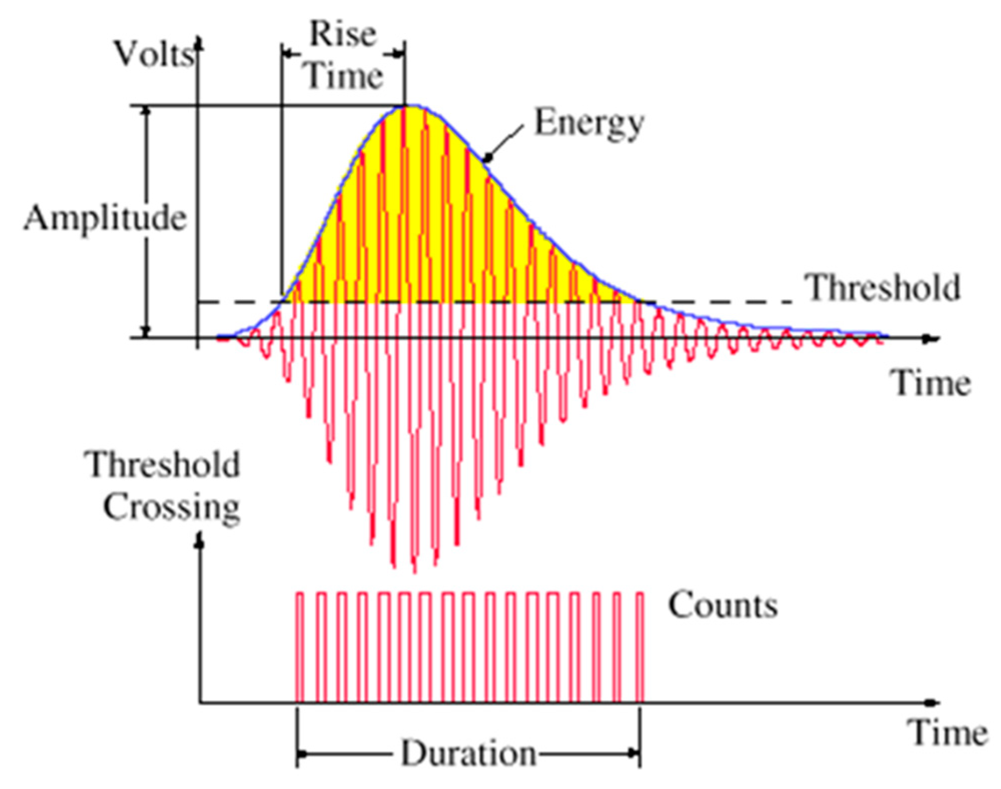
The PCI-2 AE system was used to record the AE wave forms with a sampling rate of 10 MHz. Figure 2 shows a schematic of AE wave form and its parameters. A piezoelectric sensor (PAC R15, Physical Acoustic, Princeton, NJ, USA) was used to record the AE signals. A preamplifier (2/4/6-AST, Mistras Group, Princeton, NJ, USA) with the gain selector (Mistras Group, Princeton, NJ, USA) of the 40 dB and 35 dB thresholds was used. Calibration of the sensors was done with a pencil-lead break test. The AE signal that contains parameters such as amplitude, duration, counts, rise time and energy was calculated by AE software (AEWinTM, Mistras Group, Princeton, NJ, USA).
3. Results and Discussion
3.1. Mechanical Results
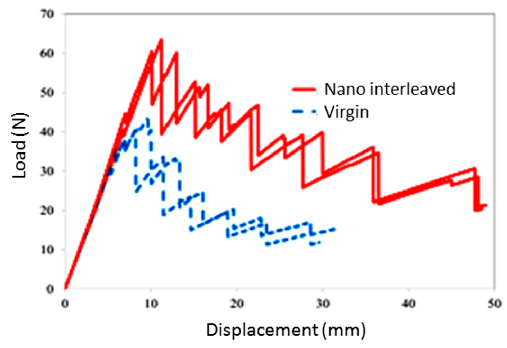
In the case of static tests, load-displacement curves for nano-interleaved and virgin samples are displayed in Figure 3, showing a multipart trend, made by ups and downs.
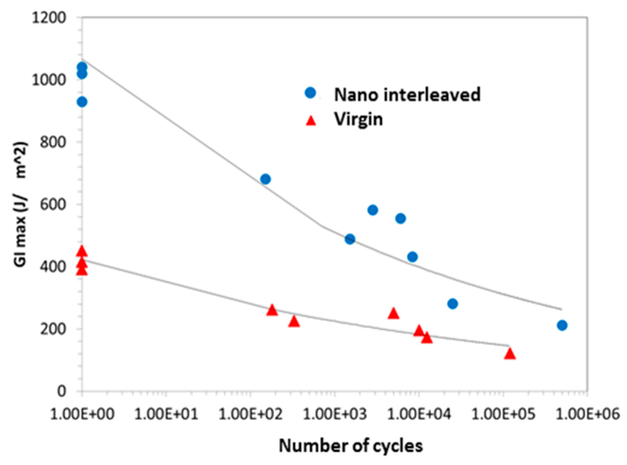
In the case of fatigue tests, the energy release rates are calculated at the peak value of different numbers of cycles using Equation (1) and then reported in Figure 4 in terms of the critical energy release rate that is required for the crack initiation under different numbers of cycles.
In particular, in Equation 1, GIC is the critical energy release rate, P is the applied load, δ is the load point displacement, B is the specimen’s width, a is the pre-crack length and ∆ is the crack growth, which can be written as:
The experimental results, by comparison between the properties for nano-interleaved and virgin samples, clearly show improvement in the fracture toughness for both static and fatigue loadings. In particular, Table 1 reports the fracture parameters obtained from mode I fracture tests measured in accordance with ASTM D5528. Specifically, in the Section 6.3 of this standard the three methods of evaluation GIC (namely “Non-linearity method”, “Visual inspection method” and “5%/max”) that have been here used for Table 1 are detailed. According to these methods, the nano-interleaved samples have shown a 120–140% increase of GIC, compared to the virgin samples. The results are coherent with similar researches as reported in [27,28]. The fracture toughness is improved at both crack initiation and propagation for the fatigue tests as illustrated in Figure 4.
3.2. AE Results
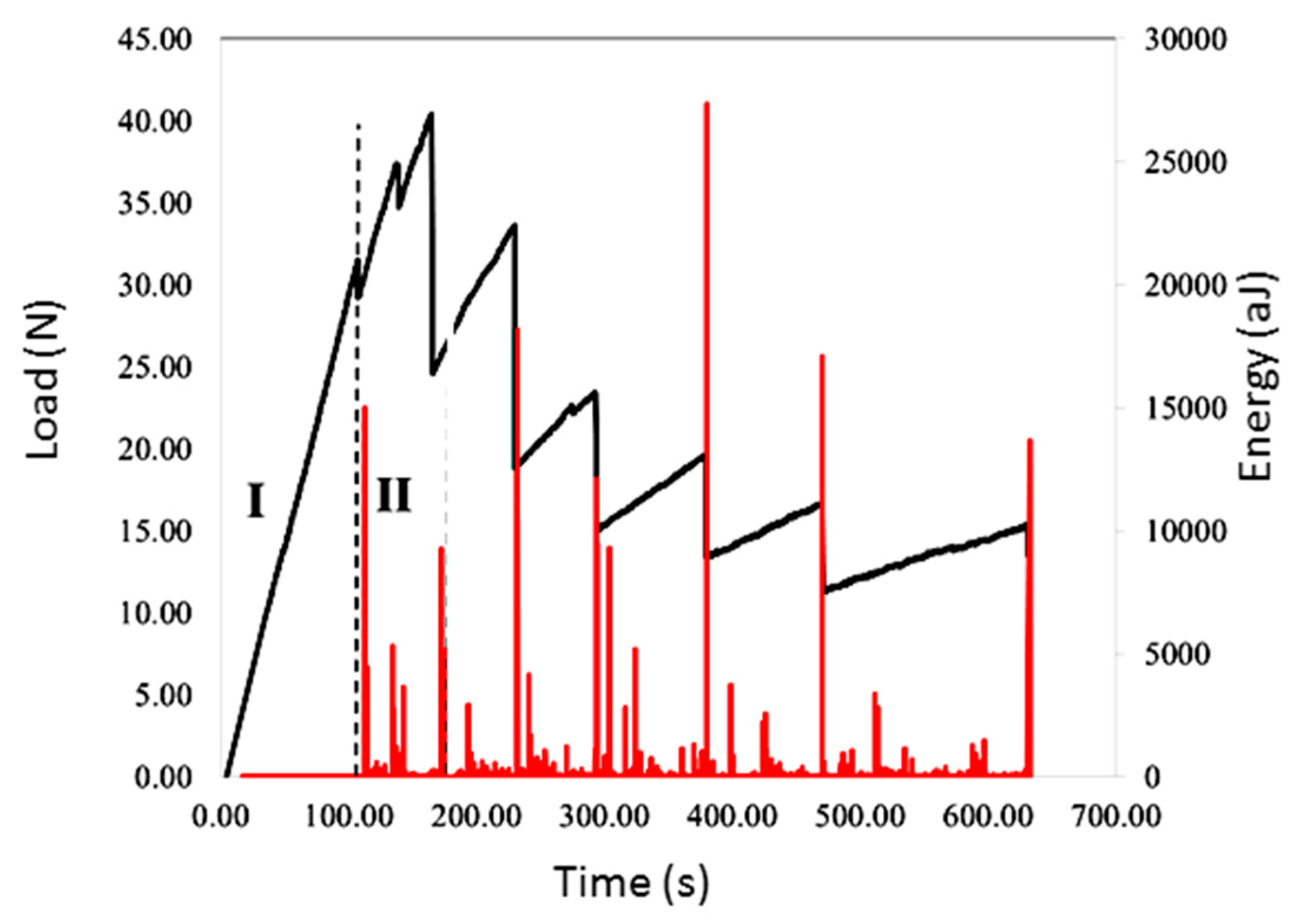
Load–time and AE energy–time curves of a virgin sample are illustrated in Figure 5 as a representation of the investigated samples behavior. The load–time is presented instead of the load–displacement diagram to be able to present the mechanical and AE data in one graph. A similar trend was observed for the nano-interleaved samples, where two different stages are observable regarding the mechanical and AE behavior as illustrated in Figure 5.
In particular, it is possible to note the presence of two different regions:
- (1)
- Linear elastic region: this is before the initiation and propagation of delamination with no major damage in the specimens, and therefore no change in mechanical data, such as stiffness, and no AE signals with high energy content.
- (2)
- Crack initiation and propagation region: crack initiation is where the delamination initiates as the strain energy level reaches the critical strain energy in the laminates. The delamination onset is recognizable where the slope of the load curve versus time decreases (non-linearity point in ASTM5528 [23]) and the first significant AE signal is observable. In the propagation stage, the pre-crack is extended and considerable AE signals appear from delamination extension and arrest, indicating development of the failure mechanisms. Induced failure mechanisms generate different types of AE signals that can provide valuable information about the type of these failures. The crack arresting stage occurs when there is an increase in the load and therefore stored strain energy. When the strain energy attains the critical value, the crack propagates again and causes different types of damage modes such as fiber breakage and matrix cracking.
This section analyzes the AE signals to recognize the failure modes. There is a wide literature about energy or amplitude-based characterization of failure modes in composite laminates [29,30,31,32,33]. These studies represent various energy and amplitude domains for the damage modes, reporting that the high domains of energy, and amplitude and frequency of AE signals are associated with fiber failure, while the middle and low domains are related to delamination/debonding and transverse/longitudinal crack of matrix, respectively. Therefore, three types of signals classification are presented in Table 2 based on the recorded AE signals in this paper. This classification is in accordance to previously published works in damage characterization of composite materials using AE or other techniques [30,31,32,33,34,35,36].
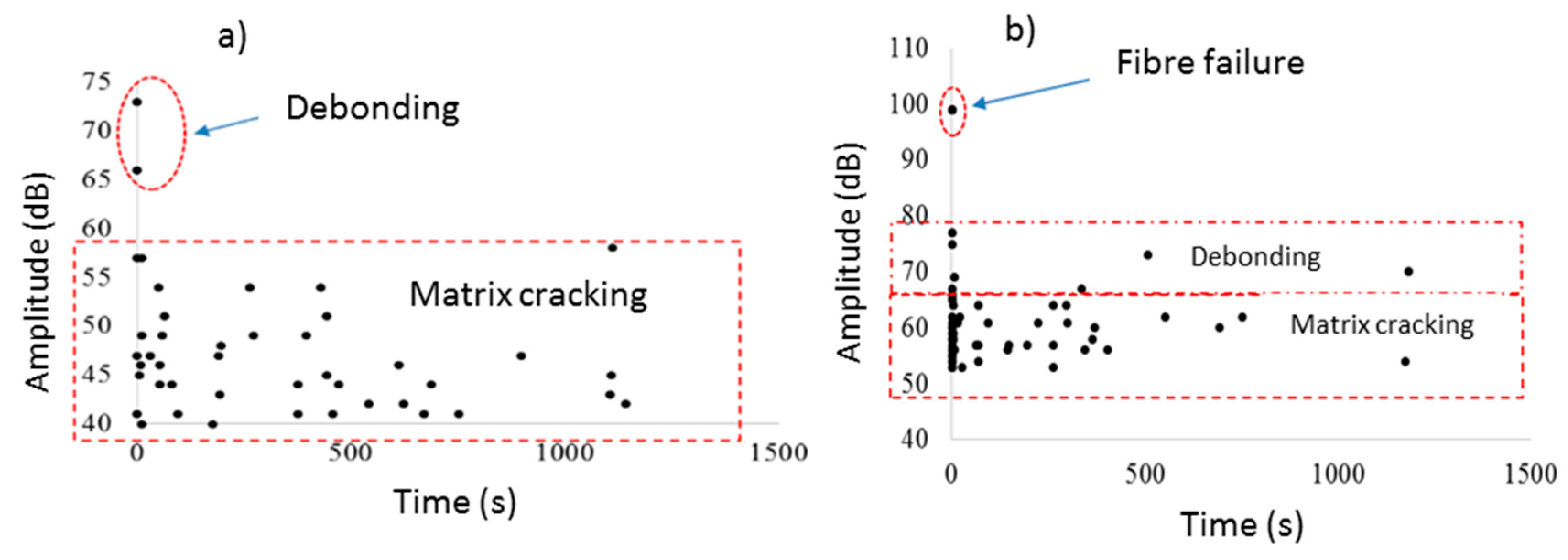
The received AE data is useful to realize the damage modes and help to understand the reason behind the improvement in the fracture toughness of the laminates. Figure 6 and Figure 7 show the obtained AE signals classified based on the aforementioned criteria for the static and fatigue loadings, respectively. The AE events appearing in the virgin samples are higher than the nano-interleaved samples (see Figure 6b). Matrix cracking-related AE signals were less in the nano-interleaved samples compared with those in the virgin samples as well.
By comparing the damage mechanisms in the fatigue loading in Figure 7, the initial damage in the virgin sample is matrix cracking and debonding, whereas the damage in the nano-interleaved sample starts with a higher amplitude that is associated with fiber breakage. It means that the toughness improvement in the modified samples does not regard the thicker resin area, but it is mainly due to the existence of tough Nylon 66 nanofibers.
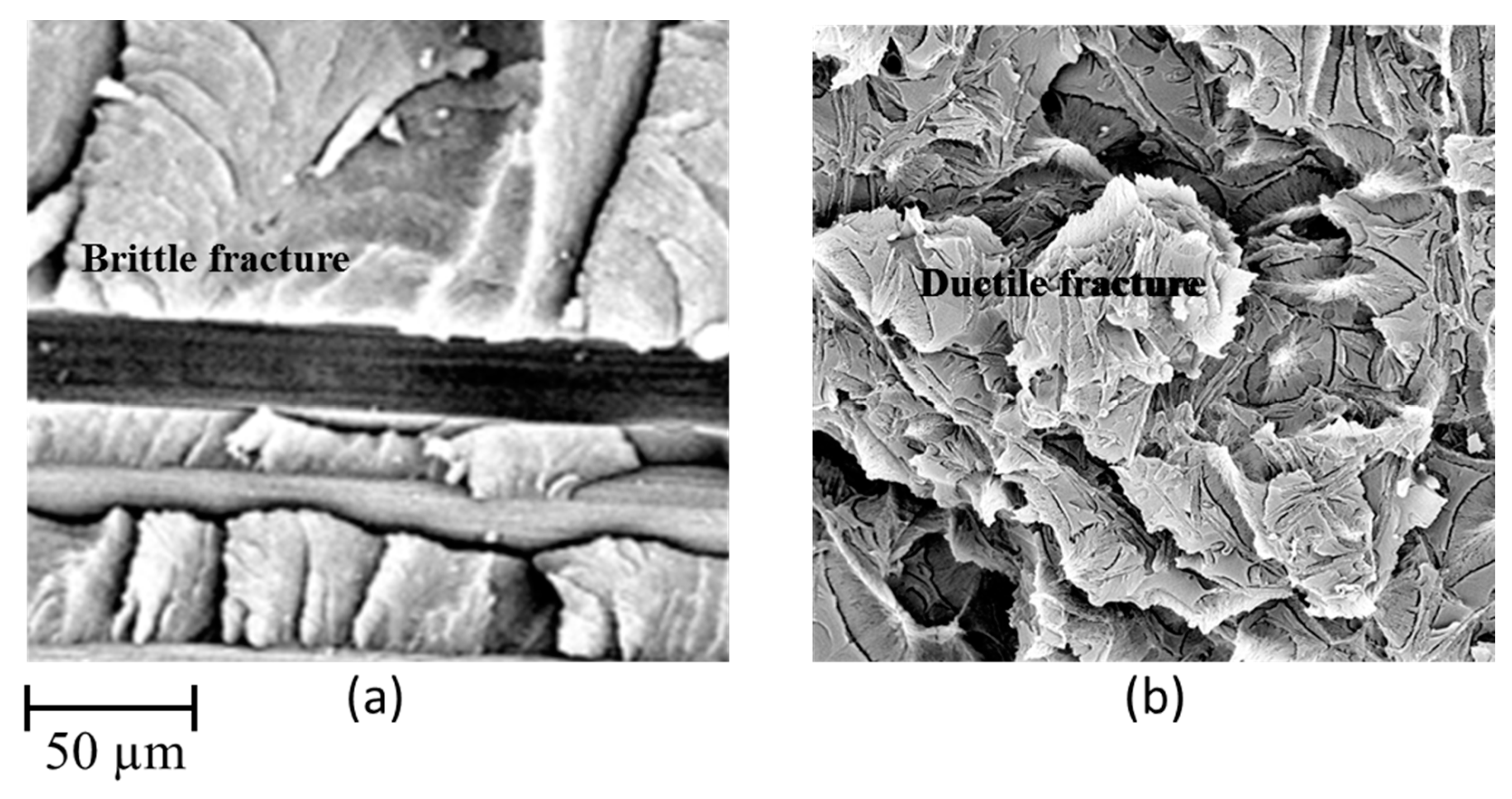
In Figure 8, the difference in morphology of the fracture surface between a virgin and a nano-modified specimen can be observed. In the case of the virgin specimen, the fracture surface is mostly represented by a matrix cracking in the resin-rich section near the fibers between two adjacent plies (Figure 8a). On the other hand, the fracture surface in the case of the nano-modified specimen is affected by the nanofiber interlayer, such that a plastic zone occurred in front of the crack tip during the crack growth (Figure 8b). It also means that, while the virgin material is mainly characterized by a brittle fracture, nano-modification provides ductility to the composites.
4. Conclusions
This paper investigated the effect of Nylon 66 nanofibers applied as additional reinforcement in CFRP composites, particularly focusing on the interlaminar properties in mode I and the failure mechanisms of carbon/epoxy laminates under the application of fatigue and static loads. Static tests based on ASTM5528 and fatigue tests based on ASTM D6115 were applied in a DCB experiment, and the samples were monitored by the adoption of AE techniques. The mechanical properties, as measured by the experiments, proved the effectiveness of the interposition of Nylon 66 nanofiber mat in improving the fracture toughness in the delamination propagation and initiation stages for both the static and fatigue loadings. The AE results also showed that the number of interlaminar failure modes occurring was reduced in the nano-interleaved samples. Specifically, by an assessment on AE signals, it was possible to note a larger matrix cracking associated to the virgin samples compared with that in the nano-interleaved ones. It means that the reason for the improved fracture toughness is the change in the damage mechanisms that require a higher energy level to initiate and propagate. Finally, it was also evident that the nano-interleaved samples show an increase in delamination resistance in every loading condition here investigated, up to 130%.
Author Contributions
Conceptualization, M.F., H.S. and G.M.; Data curation, S.F. and H.S.; Formal analysis, M.F. and C.F.; Funding acquisition, C.F.; Investigation, M.F., S.F. and H.S.; Methodology, M.F. and H.S.; Supervision, G.M.; Validation, C.F. and G.M.; Visualization, M.F.; Writing—original draft, S.F.; Writing—review & editing, C.F. and G.M.
Funding
This research received no external funding.
Acknowledgments
The Authors wish to thank Tommaso Brugo for the support in the specimens preparation and in the mechanical testing.
Conflicts of Interest
The authors declared no potential conflict of interest with respect to the research, authorship, and/or publication of this article.
References
- Tsai, G.C.; Chen, J.W. Effect of stitching on mode I strain energy release rate. Compos. Struct. 2005, 69, 1–9. [Google Scholar] [CrossRef]
- Wong, D.W.Y.; Lin, L.; McGrail, P.T.; Peijs, T.; Hogg, P.J. Improved fracture toughness of carbon Ebre/epoxy composite laminates using dissolvable thermoplastic Ebres. Compos. Part A Appl. Sci. Manuf. 2010, 41, 759–767. [Google Scholar] [CrossRef]
- Wang, C.H.; Sidhu, K.; Yang, T.; Zhang, J.; Shanks, R. Interlayer self-healing and toughening of carbon fiber/epoxy composites using copolymer films. Compos. Part A Appl. Sci. Manuf. 2012, 43, 512–518. [Google Scholar] [CrossRef]
- Tang, G.; Yan, Y.; Chen, X.; Zhang, J.; Xu, B.; Feng, Z. Dynamic damage and fracture mechanism of three-dimensional braided carbon fiber/epoxy resin composites. Mater. Des. 2001, 22, 21–25. [Google Scholar] [CrossRef]
- Van, V.P.; Ballout, W.; Daoust, D.; Sclavons, M.; Cordenier, F.; Henry, E.; Dumont, D.; Destoop, V.; Pardoen, T.; Bailly, C. Influence of thermoplastic diffusion on morphology gradient and on delamination toughness of RTM-manufactured. Compos. Part A Appl. Sci. Manuf. 2015, 72, 175–183. [Google Scholar]
- Sohn, M.S.; Hu, X.Z.; Kim, J.K.; Walker, L. Impact damage characterization of carbon fiber/epoxy composites with multi-layer reinforcement. Compos. Part B Eng. 2000, 31, 681–691. [Google Scholar] [CrossRef]
- Wu, X.; Yarin, AL. Recent progress in interfacial toughening and damage selfhealing of polymer composites based on electrospun and solution-blown nanofibers: An overview. J. Appl. Polym. Sci. 2013, 130, 2225–2237. [Google Scholar] [CrossRef]
- Fragassa, C. Effect of Natural Fibers and Bio-Resins on Mechanical Properties in Hybrid and Non-Hybrid Composites. In Proceedings of the 8th Conference on Times of Polymers & Composites: From Aerospace to Nanotechnology, American Institute of Physics (AIP), Ischia, Italy, 19–23 June 2016; Volume 1736, p. 4949693. [Google Scholar] [CrossRef]
- Koissin, V.; Warnet, L.L.; Akkerman, R. Delamination in carbon-fibre composites improved with in situ grown nanofibers. Eng. Fract. Mech. 2013, 101, 140–148. [Google Scholar] [CrossRef]
- Daelemans, L.; van der Heijden, S.; De Baere, I.; Rahier, H.; Van Paepegem, W.; De Clerck, K. Using aligned nanofibres for identifying the toughening micromechanisms in nanofibre interleaved laminates. Compos. Sci. Technol. 2016, 124, 17–26. [Google Scholar] [CrossRef]
- Yasaee, M.; Bond, I.P.; Trask, R.S.; Greenhalgh, E.S. Mode I interfacial toughening through discontinuous interleaves for damage suppression and control. Compos. Part A Appl. Sci. Manuf. 2012, 43, 198–207. [Google Scholar] [CrossRef]
- Saghafi, H.; Zucchelli, A.; Palazzetti, R.; Minak, G. The effect of interleaved composite nanofibrous mats on delamination behavior of polymeric composite materials. Compos. Struct. 2014, 109, 41–47. [Google Scholar] [CrossRef]
- Brugo, T.M.; Minak, G.; Zucchelli, A.; Saghafi, H.; Fotouhi, M. An Investigation on the Fatigue based Delamination of Woven Carbon-epoxy Composite Laminates Reinforced with Polyamide Nanofibers. Procedia Eng. 2015, 109, 65–72. [Google Scholar] [CrossRef] [Green Version]
- Fotouhi, M.; Saghafi, H.; Brugo, T.; Minak, G.; Minak, G.; Fragassa, C.; Zucchelli, A.; Ahmadi, M. Effect of PVDF nanofibers on the fracture behavior of composite laminates for high-speed woodworking machines. Proc. Inst. Mech. Eng. C J. Mec. 2017, 231, 31–43. [Google Scholar] [CrossRef]
- Marec, A.; Thomas, J.H.; Guerjouma, E.R. Damage characterization of polymer-based composite materials: Multivariable analysis and wavelet transform for clustering acoustic emission data. Mech. Syst. Signal Process. 2008, 22, 1441–1464. [Google Scholar] [CrossRef]
- Uenoya, T. Acoustic emission analysis on interfacial fracture of laminated fabric polymer matrix composites. J. Acoust. Emiss. 1995, 13, 95–102. [Google Scholar]
- de Oliveira, R.; Marques, A.T. Health monitoring of FRP using acoustic emission and artificial neural networks. Comput. Struct. 2008, 86, 367–373. [Google Scholar] [CrossRef]
- Fotouhi, M.; Pashmforoush, F.; Ahmadi, M.; Oskouei, A.R. Monitoring of initiation and growth of delaminationin composite materials using acoustic emission under quasi-static 3-point bending test. J. Reinf. Plast. Compos. 2011, 30, 1481–1493. [Google Scholar] [CrossRef]
- Pashmforoush, F.; Fotouhi, M.; Ahmadi, M. Acoustic emission-based damage classification of glass/polyester composites using harmony search k-means algorithm. J. Reinf. Plast. Compos. 2012, 31, 671–680. [Google Scholar] [CrossRef]
- Saeedifar, M.; Fotouhi, M.; Ahmadi, M.; Hosseini-Toudeshky, H. Prediction of delamination growth in laminated composites using acoustic emission and cohesive zone modeling techniques. J. Compos. Struct. 2015, 124, 120–127. [Google Scholar] [CrossRef]
- Fotouhi, M.; Ahmadi, M. Acoustic emission based study to characterize the initiation of mode I delamination in composite materials. J. Thermoplast Compos. Mater. 2014, 29, 519–537. [Google Scholar] [CrossRef]
- Bohse, J. Acoustic emission characteristics of micro-failure processes in polymer blends and composites. Compos. Sci. Technol. 2000, 60, 1213–1226. [Google Scholar]
- ASTM D5528. Standard test Method for Mode I Interlaminar Fracture Toughness of Unidirectional Fiber-Reinforced Polymer Matrix Composites; Annual Book of ASTM Standards; ASTM International: West Conshohocken, PA, USA, 2007. [Google Scholar]
- ASTM D6115. Standard Test Method for Mode I Fatigue Delamination Growth Onset of Unidirectional; Annual Book of ASTM Standards; ASTM International: West Conshohocken, PA, USA, 1997. [Google Scholar]
- Ishbir, C.; Banks-Sills, L.; Fourman, V.; Eliasi, R. Delamination propagation in a multidirectional woven composite DCB specimen subjected to fatigue loading. Compos. Part B Eng. 2014, 66, 180–189. [Google Scholar] [CrossRef]
- Huang, M.; Jiang, L.; Liaw, P.K.; Brooks, C.R.; Seeley, R.; Klarstrom, D.L. Using acoustic emission in fatigue and fracture materials research. JOM 1998, 50. Available online: https://www.tms.org/pubs/journals/jom/9811/huang/huang-9811.html (accessed on 18 January 2019).
- Palazzetti, R.; Zucchelli, A. Electrospun nanofibers as reinforcement for composite laminates materials—A review. Comp. Struct. 2017, 182, 711–727. [Google Scholar] [CrossRef]
- Rohwer, K. Models for intralaminar damage and failure of fiber composites—A review. Facta Univ. Ser. Mech. Eng. 2016, 14, 1–19. [Google Scholar] [CrossRef]
- Barré, S.; Benzeggagh, M.L. On the use of acoustic emission to investigate damage mechanisms in glass-fibre-reinforced poly-propylene. Compos. Sci. Technol. 1994, 52, 369–376. [Google Scholar] [CrossRef]
- Benmedakhene, S.; Kenane, M.; Benzeggagh, M.L. Initiation and growth of delamination in glass/epoxy composites subjected to static and dynamic loading by acoustic emission monitoring. Compos. Sci. Technol. 1999, 59, 201–208. [Google Scholar] [CrossRef]
- Guerjouma, R.E.; Baboux, J.C.; Ducret, D.; Godin, N.; Guy, P.; Huguet, S.; Jayet, Y.; Monnier, T. Nondestructive evaluation of damage and failure of fiber reinforced polymer composites using ultrasonic waves and acoustic emission. Adv. Eng. Mater. 2001, 3, 601–608. [Google Scholar] [CrossRef]
- Woo, S.C.; Choi, N.S. Analysis of fracture process in single-edge-notched laminated composites based on the high amplitude acoustic emission events. Compos. Sci. Technol. 2007, 67, 1451–1458. [Google Scholar] [CrossRef]
- Palazzetti, R.; Zucchelli, A.; Gualandi, C.; Focarete, M.L.; Donati, L.; Minak, G. Influence of electrospun Nylon 6,6 nanofibrous mats on the interlaminar properties of Gr–epoxy composite laminates. Compos. Struct. 2012, 94, 571–579. [Google Scholar] [CrossRef]
- Fotouhi, M.; Ahmadi, M. Investigation of the mixed-mode delamination in polymer-matrix composites using acoustic emission technique. J. Reinf. Plast. Compos. 2014, 33, 1767–1782. [Google Scholar] [CrossRef]
- Fotouhi, M.; Suwarta, P.; Jalalvand, M.; Czel, G.; Wisnom, M.R. Detection of fibre fracture and ply fragmentation in thin-ply UD carbon/glass hybrid laminates using acoustic emission. Compos. A Appl. Sci. Manuf. 2016. [Google Scholar] [CrossRef]
- Rademacher, T.; Zehn, M. Modal triggered nonlinearities for damage localization in thin walled FRC structures—A numerical study. Facta Univ. Ser. Mech. Eng. 2016, 14, 21–36. [Google Scholar] [CrossRef]
Figure 1.
Electrospinning and testing equipment: (a) schematic of the electrospinning process; (b) the electrospinning equipment; (c) scheme of the experiment; (d) specimens and experimental setup.
Figure 1.
Electrospinning and testing equipment: (a) schematic of the electrospinning process; (b) the electrospinning equipment; (c) scheme of the experiment; (d) specimens and experimental setup.

Figure 2.
The definitions for acoustic emission parameters [26].
Figure 2.
The definitions for acoustic emission parameters [26].

Figure 3.
Load–displacement curves of the static tests.

Figure 4.
Trend of the critical energy release rate (GImax) required for the crack initiation under different numbers of cycles in fatigue tests based on ASTM D6115.
Figure 4.
Trend of the critical energy release rate (GImax) required for the crack initiation under different numbers of cycles in fatigue tests based on ASTM D6115.

Figure 5.
Load–time and AE energy–time curves for the reference laminate.

Figure 6.
(a) Classification of the AE data by energy and amplitude levels; (b) number of the AE signals associated with different damage modes for the static loading.
Figure 6.
(a) Classification of the AE data by energy and amplitude levels; (b) number of the AE signals associated with different damage modes for the static loading.

Figure 7.
Amplitude versus time distribution of the AE signals for the fatigued samples: (a) virgin and (b) nano-interleaved.
Figure 7.
Amplitude versus time distribution of the AE signals for the fatigued samples: (a) virgin and (b) nano-interleaved.

Figure 8.
Different morphology of fracture surfaces in the case of: (a) virgin and (b) nano-modified samples.
Figure 8.
Different morphology of fracture surfaces in the case of: (a) virgin and (b) nano-modified samples.


Table 1.
Fracture parameters obtained from mode I fracture tests measured based on ASTM D5528.
| GIC (J/m2) | |||
|---|---|---|---|
| Methods | Non-Linearity Method | Visual Inspection Method | 5%/max |
| Virgin | 340 ± 15 | 385 ± 20 | 415 ± 52 |
| Nano-interleaved | 790 ± 30 | 850 ± 50 | 1000 ± 60 |
| Δ | +132% | +121% | +141% |
Table 2.
Classification of the AE signals based on their amplitude and energy content.
| Signal Type | Amplitude (dB) | Energy (aJ) |
|---|---|---|
| Matrix cracking | 40–65 | 0–30 |
| Debonding | 60–85 | 30–800 |
| Fiber failure | 75–100 | 800–65,000 |
© 2019 by the authors. Licensee MDPI, Basel, Switzerland. This article is an open access article distributed under the terms and conditions of the Creative Commons Attribution (CC BY) license (http://creativecommons.org/licenses/by/4.0/).
Share and Cite
MDPI and ACS Style
Fotouhi, M.; Fragassa, C.; Fotouhi, S.; Saghafi, H.; Minak, G. Damage Characterization of Nano-Interleaved CFRP under Static and Fatigue Loading. Fibers 2019, 7, 13. https://0-doi-org.brum.beds.ac.uk/10.3390/fib7020013
AMA Style
Fotouhi M, Fragassa C, Fotouhi S, Saghafi H, Minak G. Damage Characterization of Nano-Interleaved CFRP under Static and Fatigue Loading. Fibers. 2019; 7(2):13. https://0-doi-org.brum.beds.ac.uk/10.3390/fib7020013
Chicago/Turabian StyleFotouhi, Mohamad, Cristiano Fragassa, Sakineh Fotouhi, Hamed Saghafi, and Giangiacomo Minak. 2019. "Damage Characterization of Nano-Interleaved CFRP under Static and Fatigue Loading" Fibers 7, no. 2: 13. https://0-doi-org.brum.beds.ac.uk/10.3390/fib7020013
Note that from the first issue of 2016, this journal uses article numbers instead of page numbers. See further details here.