
Rammed Earth with Straw Fibers and Earth Mortar: Mix Design and Mechanical Characteristics Determination


Department of Civil Engineering Sciences and Architecture, Polytechnic University of Bari, Via E. Orabona 4, 70125 Bari, Italy
*
Author to whom correspondence should be addressed.
Fibers 2021, 9(5), 30; https://0-doi-org.brum.beds.ac.uk/10.3390/fib9050030
Submission received: 16 February 2021
/
Revised: 6 April 2021
/
Accepted: 20 April 2021
/
Published: 4 May 2021
(This article belongs to the Special Issue Fibres in Construction: Mechanical Modelling and Characterisation)
Abstract
:Raw earth is one of the oldest building materials, which is suitable for various uses: from the construction of load-bearing walls to use for plasters and finishes. The presence of straw fibers can give different behavior to this material. The present paper illustrates preliminary sensory and qualitative analyses, and subsequent laboratory tests that allow the characterization of the raw earth material with straw fibers for rammed earth constructions through mechanized compaction and the identification of a compatible earth mortar. The raw material considered in this study is mainly clayey; for this reason, a mix design usable with the pisé (or clay) technique has been developed. Cylindrical samples have been made through a press and subject to unconfined compression and indirect tensile tests. The results of the tests showed consistent tensile and compressive strength values in the context of earth materials. At the same time, a study for the realization of a mortar with the same base soil was carried out considering four mixtures, in order to investigate the best compromise between workability, shrinkage and compressive strengths. The purpose of the study was to investigate the mechanical characteristics of the local material through preliminary and laboratory tests, to classify it according to the Unified Soil Classification System (USCS) and to verify its suitability for a possible use in the construction field.
1. Introduction
Raw earth is one of the most utilized materials in the world, as well as having been used by most ancient civilizations. Raw earth buildings were among the first capable of guaranteeing the building’s protection from the outside and durability, thus constituting the first forms of urban settlement. By means of some archaeological excavations carried out in Italy and in the rest of the world, today it is possible to argue that the origin of the constructions made of raw earth dates back to about 6000 B.C. The most ancient examples are the mosque of Djienne in the Republic of Mali, the granaries of the temple of Ramesses in Egypt, the monastery of Tabo in India [1]. In addition to individual buildings, entire settlements were developed, such as the city of Taos in New Mexico, the city of Shibam or Manhattan of the desert, the city of Sanaa in Yemen and the citadel of Bam in Iran [1]. In Italy, the use of raw earth as a building material has been limited to only three categories: fortification, temple and housing [1].
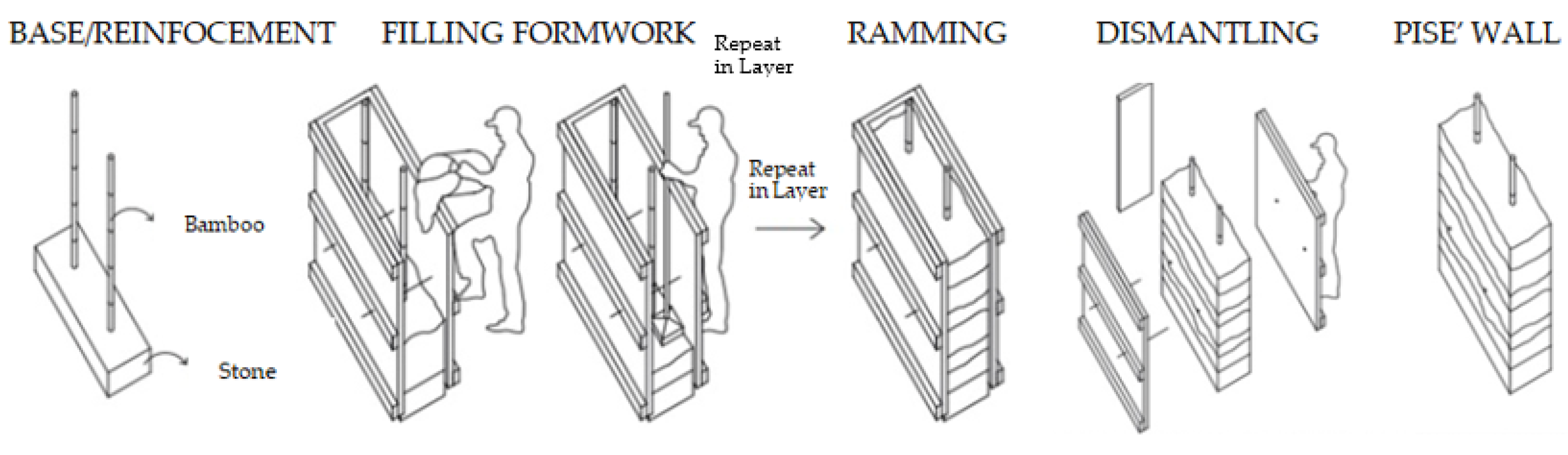
The most common techniques to make raw earth a building material are adobe, cob and clay or pisé [2]. Adobe consists of making raw earth bricks prepared manually or through a mechanized process, left to dry in the sun. It is suitable for the construction of load-bearing and infill walls [3]. Cob provides a dense and plastic mixture, made with earth and straw, modeled by hand or with automatic mixers, and stacked layer by layer, to erect walls without the aid of formwork [4]. The pisé technique consists of the compaction of damp earth inside a wooden formwork [5] to produce mainly vertical structures. The earth usually used is that of the excavations, worked on site and compacted in layers of about 15 cm (Figure 1). For pisé, lean or medium-fat earth, often stony [6], is used. Compaction is performed using water content, which is considered optimal as it provides the maximum dry density for constant compaction energy [7].
The mechanical behavior of rammed earth depends on a number of factors [9], first of all the nature of the earth, the quantity and quality of clay, the fibers added, the particle size distribution of the earth and the quantity of additions, the construction technique (Adobe, Cob and pisé) and no less influential, the method of compaction, either manual or mechanized. These factors determine the apparent density and porosity. The mechanical properties of rammed earth provided in the literature show very different values (see Table 1). It is possible to notice that the bulk density values of un-stabilized rammed earth are in the range (1700–2400 kg/m3) [10]; the corresponding axial compressive strength values are between 0.60 and 4.00 N/mm2.
The scatter of mechanical property values in the literature is large, especially in the case of Young’s modulus. It can depend on many factors such as the characteristics of the local soil, the different mix designs, the workmanship, the weathering and the different procedures for the mechanical characterization tests of the mix design. In particular, the studies in Table 1 report both manual [21,22,23] and mechanical [13,19,20] constipation.
Other uses of raw earth concern mortars and plasters reproduced by mixing earth with sand. Although these materials do not increase the mechanical strength, they are necessary for the installation of strengthening components as natural (e.g., straw fibers) or plastic nets on bearing walls and panels. The scientific literature [23,25,26,27], in fact, investigates the use of compatible textile-reinforced mortars (TRM) as reinforcement techniques for rammed earth buildings: the first studies [28] showed an improvement in the overall seismic capacity, similar to that obtained in the Adobe case [29].
To ensure the effectiveness and durability of the reinforcement technique, the characterization of each component is essential. The main control parameters for the mortar are workability, linear shrinkage and compressive and tensile strength [30]. Table 2 summarizes the data relating to the compressive strength of mortars available in the literature and the minimum values reported in the NZS 4297 and NZS 4298 standards [11,12]. In particular, both Young’s modulus (160–1034 N/mm2) and compressive strength (0.75–2.88 N/mm2) present a high scatter of values, due to the reasons mentioned above for the mix design of the mixtures of the structural elements.
The present study performed the characterization of the mix design of raw earth with straw fibers for the use of the pisé technique starting from local soil (Altamura, Italy) which was corrected and mechanically compacted in cylinders with a diameter and height of 150 mm. The goal of the study was to define the mechanical properties of the local soil (Apulia Region), through preliminary and laboratory tests, and to verify its suitability for possible use in construction, trying to standardize both the procedure for its characterization and the methodology for the realization of specimens that have a material as homogeneous as possible and a degree of compaction comparable with that of upcoming panels.
Today in Italy there is no legislation that regulates the procedures for the mechanical characterization of raw earth, both from the point of view of the material and of the structural elements, always considering that there are so many variables that it is almost impossible to establish universally valid reference values. Therefore, the characterization procedure described combines regulations and manuals from different countries with indications deriving from scientific literature studies. In addition, it is important to highlight the use of straw fibers for the pisé technique, which generally does not include any, as opposed to the adobe and cob techniques; this choice was made because the addition of straw allows containing the shrinkage phenomenon and increasing the ductility of the structural element.
To define a procedure, easily repeatable, avoiding imperfections due to the operator’s manual skills, it was decided to opt for a mechanical compaction method, preferring it to a traditional one. This distinguishes the study from most of the existing scientific literature about rammed earth that uses manual compaction, e.g., among the case studies reported in Table 1, only Jaquin [13] and Maniatidis [19,20] utilized mechanical constipation.
Furthermore, the criteria for identifying a compatible earth mortar were identified through the study of four earth and sand mixtures and the results relating to their mechanical properties.
The tests were conducted at “Madeinterra” Cooperative in San Vito dei Normanni (Brindisi, Italy), the Geotechnical Laboratory of the Polytechnic University of Bari, “TecnoLab” laboratory in Altamura (Bari, Italy) and “M. Salvati” testing materials laboratory of the Polytechnic University of Bari (Italy).
2. Materials and Methods
In the raw earth field in Italy, there is no legislation that regulates the procedures for the mechanical characterization of the material and its structural elements. This depends on two reasons: the first one, the reduced presence of buildings, if not for some examples in restricted areas of the country, and the second one, the existence of many variables that characterize the material, so that a universal identification of valid reference values is difficult. First of all, the mechanical behavior of the material is strongly influenced by the nature of the earth and above all, by the quantity and quality of the clay it contains. In the case of the pisé technique, the method of compaction, whether manual or mechanized, is also highly influential.
In order to use the earth as a building material, it is necessary to know its composition and characteristics. The tests that allow the characterization of each earth are of two types: in situ tests and laboratory tests [34].
2.1. Preliminary Knowledge Analysis In Situ
Preliminary cognitive analyses were conducted at “Madeinterra” Cooperative in San Vito dei Normanni.
A soil sample was taken from an area in the municipality of Altamura (San Giuliano Park area) at a depth of about 50 cm, in order to exclude the presence of molds and other living organisms. First, the density of the soil was calculated through the use of a cubic silicone mold with internal dimensions equal to (50 × 50 × 50) mm. The mold was then filled with pressed and well compacted earth to reach a humid density of 1.88 g/cm3, which is a non-optimal density for a mixture. The latter data will be useful in the sampling phase of the earth and subsequent preparation of the samples for estimating the quantity of earth needed for the study.
Subsequently, preliminary sensory and qualitative analyses were performed [2,34], which provide an initial assessment of the suitability of a given earth for use in construction. It is easily possible to detect the presence of organic matter, gravel or fine elements, as well as to distinguish silts from clays. Visual, olfactory, tactile, sedimentation, cohesion, cigar, adherence, resistance to dryness, collapse and washing led to the same outcome: the earth taken was mainly characterized by a clay component (Figure 2). In particular, the sedimentation test (Figure 2a) was decisive for obtaining the first percentages regarding the composition of the soil sample: 53% clay, 29% sand and 18% silt. To evaluate the plasticity of the earth, the slump test was performed (Figure 2b); in the present case, the material of the specimen resulted as plastic and clayey, where in fact the sedimentation was not significant compared to the decrease in the sample and mold. The dry resistance was verified through the realization and the failure of “medallions” of about 7 cm in diameter (Figure 2c), which were left to dry for 10 days; the material resulted as almost pure clay, and in fact the specimens broke with difficulty and did not create dust. Additionally, the “cigar test” (Figure 2d) validated the clayey nature of the earth analyzed identifying a well cohesive mixture; in fact, the cylindrical or cigar-shaped element with a length of 10 cm and a diameter of 2 cm, did not fail by making it slide by 5 cm along the edge of a plan.
2.2. Laboratory Analyses
2.2.1. Particle Size Analysis
Laboratory tests on the soils allowed to experimentally define their composition. The particle size analysis of the soil was carried out at the Geotechnical Laboratory of the Polytechnic University of Bari (Figure 3) according to the ASTM D422 standard [35] by means of two techniques, sieving for the coarse fraction (grain diameter greater than 0.075 mm) and sedimentation for the fine fraction (grain diameter less than 0.075 mm). The reference classification system was USCS [36], developed by Casagrande [37]. In this system, coarse-grained soils were classified on the basis of grain size, while fine-grained ones on the basis of plasticity characteristics (Atterberg limits), since the mineralogical composition has an important influence on the mechanical response of the material.
The particle size analysis of the soil led to obtain the weight fractions relating to each class: 49% clay, 28% sand, 19% silt or lime, 4% gravel. It is a fine-grained soil (USCS) as the ASTM 200 sieve pass-through of 77% is greater than 50%.
Figure 3 is representative of the most frequent obtained results.
2.2.2. Atterberg Limits
Atterberg limits [38] were calculated at the Geotechnical Laboratory of the Polytechnic University of Bari both on natural soil and on soil dried at 105 °C for 24 h. The measured values of the liquid limit wL are 40.4% for the soil in the natural state and 40.6% for the soil subject to the pre-drying treatment; those of the plastic limit wP are, respectively, 19.9 and 19.8%. The IP plasticity index is equal to 20.5% for the soil in the natural state and 20.8% for the pre-dried soil. They are comparable values; therefore, it is clear that the organic component is almost entirely non-existent, or in any case not very influential. Consequently, no pre-treatment is necessary. The soil activity index, with an ASTM 200 sieve, is equal to 0.42. The material under examination, therefore, is an inorganic and inactive clay with medium plasticity (CL classification USCS).
2.3. Rammed Earth Mix Design Characterization
2.3.1. Mix Design
Rammed earth constructions consist of sand, silt, clay and gravel; straw fibers are also added in the mix design in a second step. For the pisé technique, it is important that each of these classes is present in the soil in correct proportions. In the raw earth constructions, regardless of the technique, the presence of clay is decisive [39] as the latter has binding properties, which are essential for the performance of the final material, but at the same time entails a high shrinkage [40]. From a comparison with the literature on raw earth constructions [22,41,42,43], the soil in question “soil S1” was too clayey; so it was degreased with river sand to improve resistance to atmospheric agents, fine calcareous gravel (4–8 mm) and coarse calcareous gravel (16–32 mm) were utilized to improve structural stability.
In particular, the first correction S2 was created by mixing 45% of soil and 55% of river sand. It is observed that the contribution of the clay fraction has been reduced by about half, from 49 to 24%.
A second correction S3 was performed following a more scientific approach to obtain a particle size distribution closer to the Füller curve, allowing to optimize the density of the rammed earth and therefore the relative mechanical performances. In the Füller grain–size curve [40], the non-perfect spherical shape of the particles has been taken into consideration [31].
The corrected soil S3 consists of 30% of original soil, 30% river sand, 30% of fine gravel and 10% of coarse gravel (by weight). The new curve obtained was compared with the grain particle size distribution (PSD) curves recommended by Houben and Guillaud [44] and by the Portuguese National Laboratory of Civil Engineering LNEC [45] (Figure 4). Therefore, the final S3 is composed of 42% sand, 35% gravel, 16% clay and 7% lime; it is found within the two PSD envelopes considered and is similar to the compositions of the soils used for the pisé technique, indicated by other studies in the literature (Table 3).
2.3.2. Laboratory Tests: Proctor Test
The compaction capacity is a fundamental property of clay. To achieve the maximum compaction, earth must have a specific water content, the so-called “optimal water content” (OWC), which allows the particles to be brought into a denser configuration without too much friction. The Proctor test [51] was carried out at the “TecnoLab” laboratory in Altamura (Italy) and was performed on S1, S2 and S3. For each specimen, a different number of tests was carried out involving the realization of samples with different quantities of water, keeping the compaction energy constant and starting from about 6 kg of material. As defined in [31], soil samples with a dry density between 1.76 g/cm3 and 2.10 g/cm3 have satisfactory performance, and those between 2.10 g/cm3 and 2.20 g/cm3 are excellent.
The test was first performed directly on S1, finding a very high-water content of 20.5% and a very low maximum dry density of 1.67 g/cm3. These values confirm the unsuitability of the original soil to be used in construction: the water content would cause a considerable shrinkage and a wall made with this material would have insufficient performance, due to its low-density value.
The obtained OWC for S2 is equal to 13.8% with a maximum dry density equal to 1.77 g/cm3, and indeed for S3, the maximum dry density value resulted as equal to 2.05 g/cm3 and the optimal water content equal to 8.9%. Figure 5 represents the graph of the dry density variation as a function of the water content of S3.
These results confirm that the selected mix has the qualities necessary to be used in the clay technique. The obtained water content guarantees a low probability of shrinkage cracking.
2.3.3. Laboratory Tests: Realization of Specimens
Eight cylindrical specimens were made for S3 mix, six to determine the compressive strength and two for the tensile strength. The cylinders (with dimensions d = 15 cm and h = 15 cm) were compacted in two layers, inside a steel mold and with the aid of a gyratory press, “Matest Gyrotronic”, at the “TecnoLab” laboratory in Altamura. Furthermore, it is important to highlight that the Proctor test allows to archive the sample’s optimal compaction conditions. The choice of making the specimen with two layers was intended to reproduce the stratigraphy that characterizes the pisé technique on the sample.
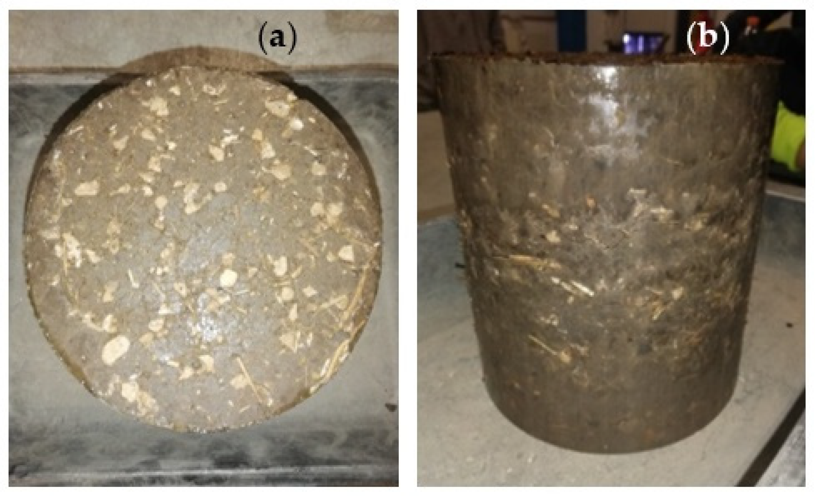
Scientific literature, manuals and legislation [12] often recommend adding fibrous elements such as straw to the raw earth mixture. One of the main reasons for their use is certainly the increase in the compound’s tensile strength, but also the improvement of the material ductility. Generally, the amount of straw is closely related to the added quantity of water in a raw earth mixture, as it helps to reduce shrinkage and cracking during the drying process. The adobe and cob techniques involve the use of mixtures in which a greater amount of water is added than the pisé technique. For these two techniques, the studies report a quantity of straw in regard to the total weight of mixture, respectively, for the adobe smaller than 3% in [34] and between 0.5 and 8% in [52] (although it is specified that in the traditional Peruvian technique the percentage is smaller than 0.5) and instead in a range between 1 and 3% [53] for cob. Therefore, for pisé, having no other references in the literature and using a soil with its natural humidity, a lower value was chosen than for the other two techniques. Then, the 0.25% percentage by weight of dry straw fiber was added, chopped into small elements with a maximum length of 3 cm, clearly distinguishable in the mix of the rammed earth specimens. As recommended by the literature that reports adobe and cob cases, straw was cut into strips with a length not exceeding half the thickness of the finished wall [12]. Wheat straw was chosen because it has already been used in some rural houses in Italy realized with the adobe technique [34]. In addition, the wheat straw chosen comes from the local cultivation of the “Murgia”, an area near the Municipality of Altamura. From laboratory tests, the mechanical properties of the wheat straw was obtained; in particular the Young’s modulus, which is in the range of 5–6 GPa, the average tensile strength which is in the range between 22 and 79 MPa and the average water absorption, which is in the range between 280% and 300%. In this case, straw was used to limit the sensitivity to water, help the setting phenomenon and reduce shrinkage cracks [39]. After the compaction process (by means of 5 tons load), the cylinders were immediately demolded with the aid of compressed air to facilitate their extraction (Figure 6).
Each S3 cylinder has a wet weight of approximately 6.0 kg and a wet density of approximately 2.28 g/cm3. The average value of the specimen’s maximum dry densities was 2.07 g/cm3, which demonstrates the reliability of the Proctor test considering that the maximum value was equal to 2.05 g/cm3.
The specimens were placed in a climatic chamber for at least 28 days. The tests were performed after the samples reached the water content in equilibrium (at 22 ± 2 °C and at a relative humidity of 50%), which was found on average at 2.0%.
2.3.4. Laboratory Tests: Simple Compressive Test
To determine the compressive strength and Young’s modulus, six cylindrical specimens were subject to non-confined compressive tests at the “M. Salvati” laboratory of the Polytechnic University of Bari. The specimen type used for the test is shown in Figure 6.
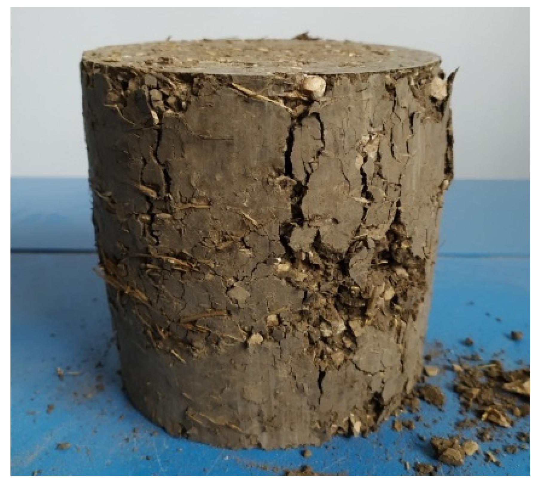
The INSTRON 5869 press was used and programmed in such a way to ensure the gradual and controlled application of displacement knowing the initial height of the specimens; and a layer of about 1.00 mm of damp earth was interposed on the upper and lower faces to reduce the irregularities. Therefore, the test was displacement-driven and the specimen failure was carried out only after running three complete cycles (Figure 7 and Figure 8); they showed that the material assumes an elastic behavior. For each cycle, the test equipment detected the longitudinal displacements reporting a typical stress–strain curve through the data processing software (Figure 8).
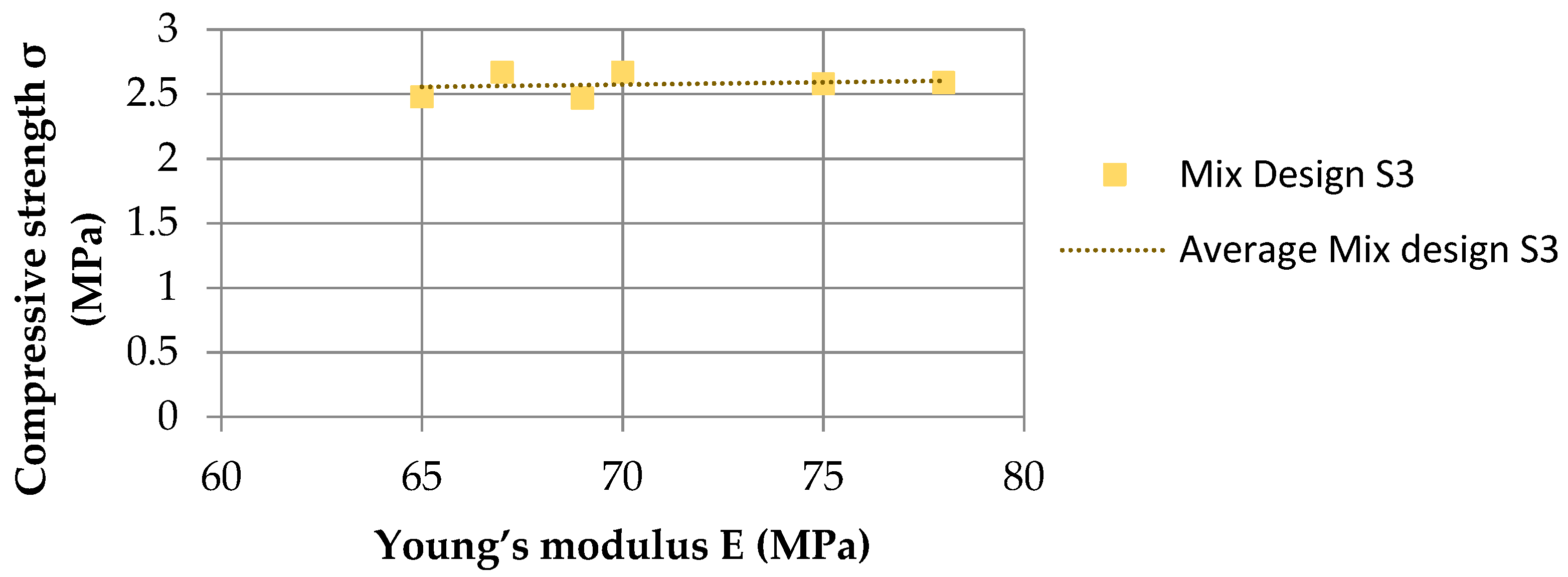
The compressive strength values obtained show a mean value equal to 2.58 MPa, a standard deviation (SD) equal to 0.08 and a relative standard deviation (RSD) equal to 3.10%. This low SD value can be explained by the use of the gyratory press which allowed to obtain similar specimens as made with a standard production method.
The longitudinal elastic modulus (Young’s modulus E) is calculated through a linear regression considering the peak stress in the range between 5 and 30% [36].
By relating the Young’s modulus to the corresponding experimentally measured compressive strength value, the obtained coefficient ratio is approximately 30 for S3 mix.
For further confirmation, the specimens of the mix design S2 were tested anyway. As expected, the compressive strength values are lower than S3; in particular, the S2 average value is equal to 1.59 MPa. In fact, it is important to consider the density factor which positively affects to the compressive strength of the specimens: S3 density is greater than S2 density.
2.3.5. Laboratory Tests: Indirect Tensile (Brazilian) Test
The test was performed at the “TecnoLab” laboratory using a CONTROLS 65-L1200 automatic press (Figure 10) according to the code [54]. Two cylindrical specimens were tested with a diameter and height equal to 150 mm, so with a ratio equal to 1. The values obtained for the tensile strength fct are reported in Table 5.
The failure of S3 specimens showed pseudo-vertical cracks, slightly curved in the central part due to the presence of coarse limestone gravel particles along the failure plane (Figure 10a). It has been possible to determine the cohesion (c) and friction angle () of the soil S3 through the following relations:
2.3.6. Results Discussion
To compare the obtained values from the compressive test with those of the literature, reported in Table 1, for the Young’s modulus it was necessary to consider the value of the maximum peak between 5 and 30%, through linear regression, since the literature data were calculated under such conditions. Most of the studies in Table 1 were carried out on cylindrical specimens with an h/d ratio equal to 2 and a cross-section equal to 100 mm, with the exception of [17,18], who use cubic specimens. Unfortunately, in the present study, h/d = 2 could not be utilized, nor the same cross-section due to the instrumental limitations. As a consequence, conversion factors were used as indicated in [55] to compare the compressive strength values. Therefore, the compressive strength values were multiplied by two factors k1 = 1/1.18 = 0.85 and k2 = 1.02, the first to take into account the different slenderness, and the second to take into account the different cross-section dimension of the specimens with the same h/d [56]. At the end, the final compressive strength values, initially equal to 2.58 MPa for S3_1–S3_6 are now equal to 2.23 MPa. The compressive strength results of S3_1–S3_6 specimens comply with NZS 4298 [12] and are comparable with the studies [19,20], since the same methods of soil correction and mechanical compaction are used. As a result, the data of the case study can be considered consistent.
In the scientific literature, there are several studies concerning the Young’s modulus (see Table 1), that show a great dispersion for both for the un-stabilized and stabilized rammed earth within a range of 60–4150 MPa [10,13,14,15,16,17,18,19,20,21,22,23,24]. This is due to many factors like the type of the soil, the workmanship and the testing procedures. In the present study, the Young’s modulus reaches values of around 70 MPa, as in [13,14,24].
With reference to the tensile strength, there are few studies in the literature which do not allow a direct comparison. Furthermore, in some studies, as in [16], considering the relationship that exists between compressive strength and tensile strength in rammed earth constructions, this parameter is assumed to be equal to fct = 0.11 fc. This occurs for S3 Mix design (see Table 6); in case this factor is higher, this means that the tensile strength of rammed earth with straw has interesting results.
The results achieved allow to consider S3 as the mix compliant with regulations and guidelines [12,40,45] for rammed earth constructions both from a quantitative and qualitative point of view. In fact, it is the suitable mix for erecting rammed earth constructions: it contains fine and coarse gravel for structural stability, sand for greater resistance to atmospheric agents, as well as silt and clay for greater cohesion [31].
2.4. Earth Mortar Characterization
2.4.1. Mix Design
The experimental campaign involved the realization of four earth mortars to be used both as non-structural finishes (internal and external coatings) and as structural part connections and/or strengthening devices for rammed earth walls. In particular, it is used as compatible support for any seismic reinforcement with a fabric net, which is necessary to redistribute the stresses inside the bearing wall and increase its ductility.
The investigated mixture does not consider any stabilizing, opting for clay as the only binding element. In this way, maximum compatibility with earth structures is obtained, guaranteeing strong adhesion, even in the case of subsequent installation. Before the use, the soil was sieved through a 2 mm sieve, according to the recommendations given by Röhlen and Volhard [47] for mortars in earth constructions. Each mixture was obtained by adding a different amount of river sand to S1 (Table 7). Sand was added, necessary to avoid high shrinkage, and therefore to reduce the risk of cracking during drying; this also increases the workability of the material by acting on the water content.
2.4.2. Laboratory Tests: Realization of the Specimens
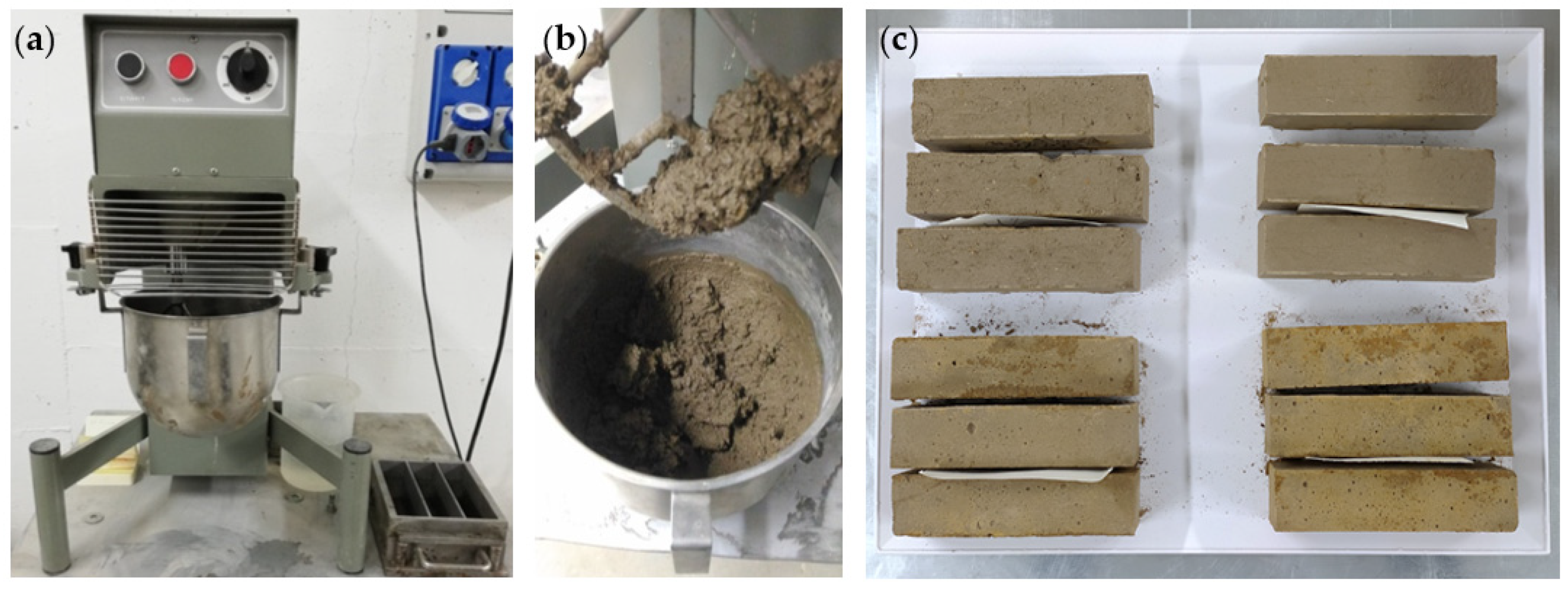
For the realization of the four mixes, earth and dry sand (previously sieved [47]) were placed inside an industrial mixer and mixed for 30 s. Subsequently, water was added and kneading proceeded for 90 s more. Once the mixture was produced, three prismatic specimens were realized for each mixture, in a steel mold, with dimensions of (160 × 40 × 40) mm (Figure 11). Before the use, the molds were doused with oil, to facilitate sample removal. Once filled, the molds were placed on a mortar setter (60 consecutive hits) to remove any remaining cavities. After filling all the gaps and leveling the surface by means of a spatula, the molds were covered with a slide, and all the samples were stored in a climatic chamber for a period of 28 days, at a constant temperature and humidity (at 22 ± 2 °C and 50% relative humidity).
2.4.3. Laboratory Tests: Evaluation of Linear and Volumetric Shrinkage
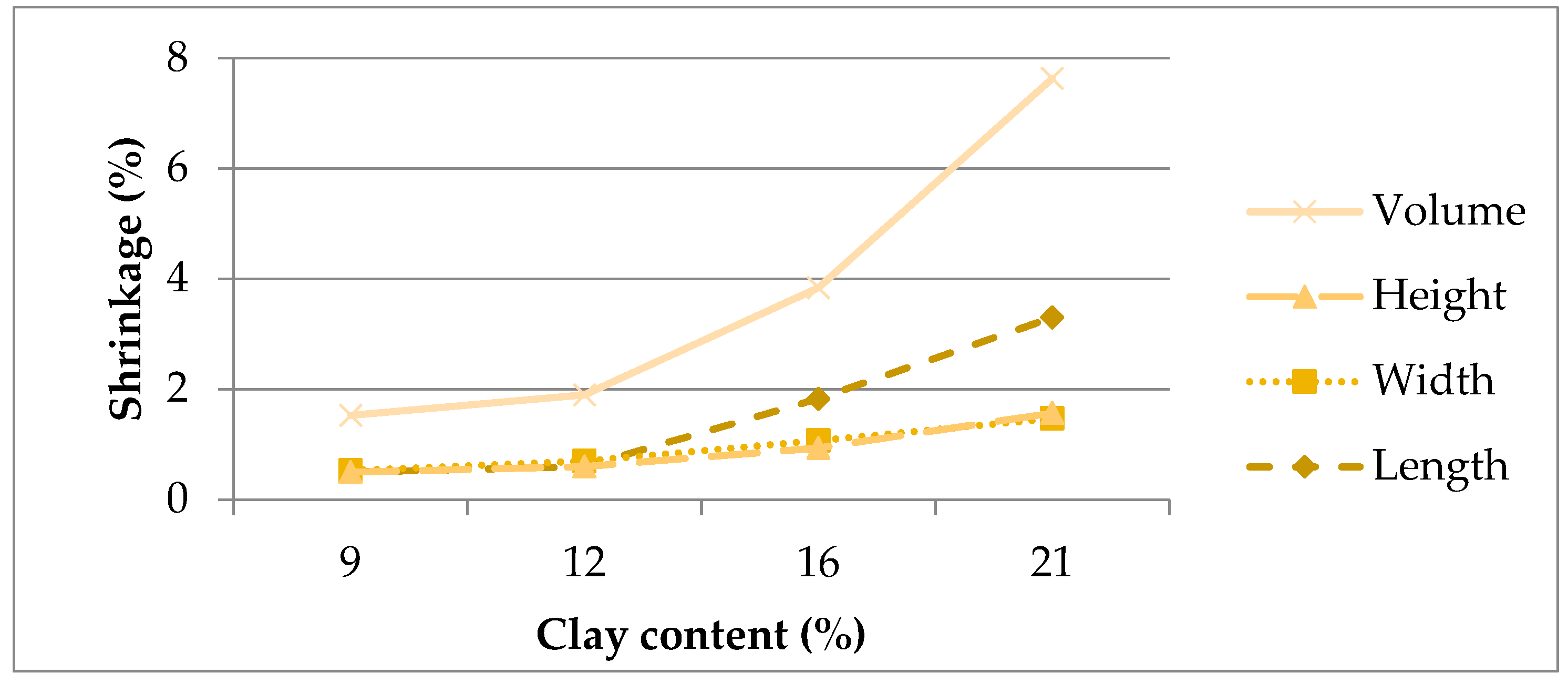
Shrinkage is important as it can cause the earth mortar to crack. Shrinkage cracks due to drying trigger, in fact, could produce further cracks; as a consequence, water can easily penetrate, negatively affecting the mechanical characteristics. Therefore, low shrinkage is essential to have a safe and compatible mortar layer. The New Zealand standards [12] state that the linear shrinkage of an un-stabilized earth mortar should never exceed 3%, Gomes [30] reduces this value to 2%. After 28 days of drying in a climatic chamber at a constant temperature and humidity, the linear and volumetric shrinkage was assessed (see Table 8). All mortars have verified the limit linear shrinkage of 3%, established by [12], with the exception of the M1 mortar. Furthermore, M3 and M4 mortars satisfied the limit shrinkage values of 2% as well. Therefore, M1 and M2 mortars were excluded, exceeding the limit of 2%.
As expected, shrinkage was higher for mortars with higher clay content. The effect is evident in both linear and volumetric shrinkage. In this case, the relationship seems to be of a higher order than linear, increasing more with the clay content: a 4% variation in the quantity of clay component determines approximately a doubling of the volumetric shrinkage value (Figure 12).
The test carried out allows to determine the dry bulk density of the mortars equal to ρ = 1.75 ± 0.03 g/cm3.
2.4.4. Laboratory Tests: Three-Points Bending Test
The bending strength was tested using a CONTROLS 65-L1200 automatic press compliant with UNI EN 1015-11 [56]. The equipment is configured in a controlled load mode, with a constant speed equal to 0.01 N/mm2s (minimum value that can be set) and permit to perform the bending test on three points, through the deflection of the samples up to break in two stumps (Figure 13). The maximum load was automatically recorded and it is possible to determine the bending strength ft in relation to its geometry:
where l1 is the distance between the supports, l2 and h are the width and height of the specimen and Ft is the maximum force applied. The results are summarized in Table 9.
2.4.5. Laboratory Tests: Simple Compressive Test
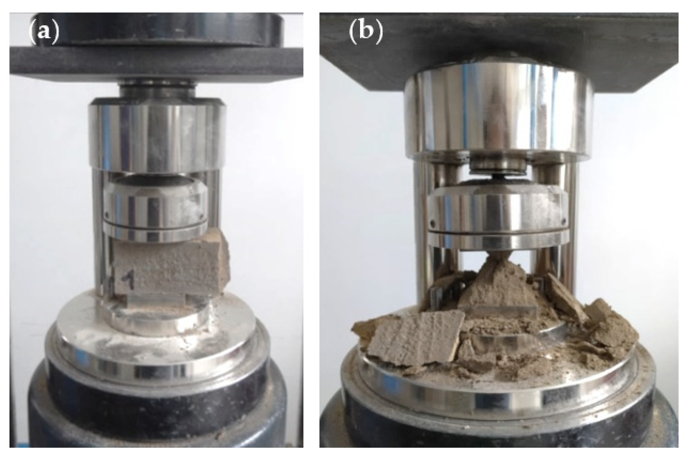
The portions resulting from the bending failure of the mortars were used for the simple compression tests (Figure 14). Each sample was split in two parts, thus, a total of six compression tests were performed for each kind of mortar.
The tests were carried out according to UNI EN 1015-11 [56] at “TecnoLab” laboratory by means of the CONTROLS 65-L1200 press; in this case, the load is uniformly transmitted through a 40 × 40 mm plate to the specimen (Figure 14a). Therefore, the equipment considers only the contact square area between the plate and the specimen, equal to 1600 mm2, to return the value of the compressive strength fc according to the formula (4):
where A is the square area section of the sample subject to compressive load and Fc the maximum force applied or compressive strength. The results are reported in Table 9.
2.4.6. Results Discussion
The mechanical characteristics of the mortar were evaluated from the three-point bending test and the compression test on prismatic samples.
From Table 9, it can be noticed that the compressive and bending strength values increase as the amount of clay present in the mortar sample increases. In fact, the highest values are obtained for M1 mortar with a percentage of clay equal to 21% and on the contrary, for M4 mortar, characterized by a 9% clay component, the lowest values were obtained. The results are in line with those found in the literature in Table 2; in particular, they confirm the Barroso [57] trend. Furthermore, the compressive strength is approximately 2.5 times greater than the bending strength, which is in line with expectations. After the test campaign on the mortars, the values were compared with the limit values imposed by the NZS 4298 standards [12] on the earth mortar, which establish for mortars a minimum compressive strength of 1.3 MPa and a minimum bending strength of 0.25 MPa.
The shrinkage test was also performed and showed that the mortar shrinks more when there is more water in the mix design. For this reason, even if the maximum strength values were recorded for M1, M1 and M2 mortars were not considered, as they did not reach the theoretical limits established in the literature [30], while M3 mortar was considered the most compatible both for its excellent workability and low shrinkage.
3. Conclusions
In the present study, the mechanical properties of raw earth added to straw fibers for the pisé construction technique, and of a compatible earth mortar, were tested and evaluated. The goal was to create a consistent mix design for the compacted earth technique in the construction field, starting from the definition of the base material through USCS classification. The compressive and tensile strength values were obtained and compared with other experimental studies.
Scientific literature and mechanical characterization of the specific design mixes with the addition of a fiber percentage for the pisé technique is very scarce and even absent. The present study tends to fill this gap.
The results confirm that:
- Fibers would increase the ductility of earth elements and the consequent mechanical production and compaction methods for the specimens, as occurred for the pisé walls;
- The compaction method is reliable as the compressive strength values are very similar to each other and therefore constant, settling around a value consistent for the raw earth material;
- Due to the presence of straw in the earth mix, the tensile strength can be considered of interest for future studies, also taking into account the lack of data;
- The compatible earth mortar results comply and are consistent with all the requirements in terms of workability, linear shrinkage and mechanical characteristics.
Further advancements in the field of rammed earth walls are under development: they will be the subject of future studies complementary to the results here presented.
Author Contributions
Methodology, formal analysis, investigation, M.T. and C.F.; data curation, M.F.S.; writing—original draft preparation, M.F.S., M.T. and C.F.; Conceptualization, writing—review and editing, supervision, D.F. All authors have read and agreed to the published version of the manuscript.
Funding
This research received no external funding.
Data Availability Statement
The data presented in this study are available in the article.
Acknowledgments
“Madeinterra” cooperative in San Vito dei Normanni (Brindisi), the “Geotechnical Laboratory” of the Polytechnic University of Bari, “TecnoLab” laboratory in Altamura (Bari) and “M. Salvati” testing and materials laboratory of the Polytechnic University of Bari are acknowledged for the support given to the present research.
Conflicts of Interest
The authors declare no conflict of interest.
References
- Galdieri, E. Le Meraviglie Dell’architettura in Terra Cruda; Editori Laterza: Bari, Italy, 1982. (In Italian) [Google Scholar]
- Houben, H.; Guillaud, H. Traité de Construction en Terre; Parentheses: Marseille, France, 2006. (In French) [Google Scholar]
- Guadagni, A. Prontuario Dell’ingegnere, 3rd ed.; Hoepli Editore: Milano, Italy, 2010. (In Italian) [Google Scholar]
- Anger, R.; Fontaine, L. Bȃtir en Terre. Du Grain de Sable à L’architecture; Belin: Paris, France, 2009. (In French) [Google Scholar]
- Houben, H.; Guillaud, H. Earth Construction: A Comprehensive Guide, 2nd ed.; Practical Action Publishing: Rugby, UK, 2008. [Google Scholar]
- Bertagnin, M. Il Pisé e La Regola; Alinea: Firenze, Italy, 1981. (In Italian) [Google Scholar]
- Bui, Q.B.; Morel, J.C.; Hans, S.; Meunier, N. Compression behaviour of non-industrial materials in civil engineering by three scale experiments: The case of rammed earth. Mater. Struct. 2009, 42, 1101–1116. [Google Scholar] [CrossRef]
- Plataforma Arquitectura. Available online: https://www.plataformaarquitectura.cl/cl/801069/25-manuales-de-autoconstruccion-diseno-y-arquitectura-participativa-en-mexico-parte-1?ad_medium=gallery (accessed on 5 February 2021).
- Vargas-Neumann, J. Earthquake resistant rammed earth (tapial) buildings. In Proceedings of the 7th International Conference on the Study and Conservation of Earthen Architecture TERRA 93, Silves, Portugal, 24–29 October 1993; pp. 140–151. [Google Scholar]
- Röhlen, U.; Ziegert, C. Lehmbau-Praxis: Planung und Ausfϋhrung, 3rd ed.; Beuth Praxis (Beuth Verlag GmbH): Berlin, Germany, 2020. (In German) [Google Scholar]
- New Zealand Standards: NZS 4297. In Engineering Design of Earth Buildings; Standards New Zealand; The trading arm of theStandards Council: Wellington, New Zealand, 1998.
- New Zealand Standards: NZS 4298. In Materials and Workmanship for Earth Building; Standards New Zealand; The trading arm of theStandards Council: Wellington, New Zealand, 1998.
- Jaquin, P.A.; Augarde, C.E.; Gerrard, C.M. Analysis of Historic Rammed Earth construction. In Proceedings of the 5th International Conference on Structural Analysis of Historical Constructions SAHC 2006, New Delhi, India, 6–8 November 2006; pp. 1091–1098. [Google Scholar]
- Jaquin, P.A.; Augarde, C.E.; Gerrard, C.M. Historic rammed earth structures in Spain: Construction techniques and a preliminary classification. In Proceedings of the International Symposium on Earthen Structures, Bangalore, India, 22–24 August 2007; pp. 327–333. [Google Scholar]
- Dierks, K.; Ziegert, C. Kapelle der Versöhnung—Schlussbericht zur Fremdϋberwachtung Forschungs– und Seminarbericht des Fachgebietes Tragwerkslehre und Baukonstruktion der TU Berlin. 2000. (In German). Available online: https://www.tek.tu-berlin.de/menue/forschung/lehmbau/ (accessed on 17 January 2021).
- Bui, T.T.; Bui, Q.B.; Limam, A.; Maximilien, S. Failure of rammed earth walls: From observations to quantifications. Constr. Build. Mater. 2014, 51, 295–302. [Google Scholar] [CrossRef] [Green Version]
- Hall, M.; Djerbib, Y. Rammed earth sample production: Context, recommendations and consistency. Constr. Build Mater. 2014, 18, 281–286. [Google Scholar] [CrossRef]
- Lilley, D.M.; Robinson, J. Ultimate strength of rammed earth walls with openings. Proceedings of the Institution of Civil Engineers (ICE). Struct. Build. 1995, 110, 278–287. [Google Scholar] [CrossRef]
- Maniatidis, V.; Walker, P.; Heath, A.; Hayward, S. Mechanical and thermal characteristics of rammed earth. In Proceedings of the International symposium on Earthen Structures, Bangalore, India, 22–24 August 2007; pp. 205–211. [Google Scholar]
- Maniatidis, V.; Walker, P. Structural capacity of rammed earth in compression. J. Mater. Civil. Eng. 2008, 20, 230–238. [Google Scholar] [CrossRef]
- Miccoli, L.; Mϋller, U. Characterization of earthen materials. A comparison between earth block masonry, rammed earth and cob. In Proceedings of the 8th International conference on Structural Analysis of Historical Constructions SAHC 2012, Wroclaw, Poland, 15–17 October 2012; pp. 841–849. [Google Scholar]
- Miccoli, L.; Mϋller, U.; Fontana, P. Mechanical behaviour of earthen materials: A comparison between earth block masonry, rammed earth and cob. Constr. Build Mater. 2014, 61, 327–339. [Google Scholar] [CrossRef]
- Romanazzi, A.; Oliveira, D.V.; Silva, R.A. Experimental Investigation on the Bond Behavior of a Compatible TRM-based solution for rammed earth heritage. Int. J. Archit. Herit. 2019, 19, 1042–1060. [Google Scholar] [CrossRef]
- Yamín Lacouture, L.E.; Phillips Bernal, C.; Reyes Ortiz, J.C.; Ruiz Valencia, D. Estudios de vulnerabilidad sismica rehabilitacion y refuerzo de casas en adobe y tapia pisada. Apunt. Rev. Estud. Sobre Patrim. Cult. J. Cult. Herit. Stud. 2007, 20, 286–303. (In Spanish) [Google Scholar]
- De Felice, G.; De Santis, S.; Garmendia, L.; Ghiassi, B.; Larrinaga, P.; Lourenço, P.B.; Oliveira, D.V.; Fabrizio Paolacci, F.; Papanicolaou, C.G. Mortar-based systems for externally bonded strengthening of masonry. Mater. Struct. 2014, 47, 2021–2037. [Google Scholar] [CrossRef]
- Borri, A.; Corradi, M. FRP: Fiber Reinforced Polymers. I Materiali Innovativi Nell’edilizia e Nel Restauro; Recupero e Conservazione; De Lettera: Milano, Italy, 2001. (In Italian) [Google Scholar]
- Torrealva, D. Static and dynamic testing for validating the polymer grid as external reinforcement in earthen buildings. In Proceedings of the 16th International Brick and Block Masonry Conference, Padova, Italy, 26–30 June 2016. [Google Scholar]
- Fagone, M.; Loccarini, F.; Ranocchiai, G. Strength evaluation of jute fabric for the reinforcement of rammed earth structures. Compos. Part B Eng. 2017, 133, 1–13. [Google Scholar] [CrossRef]
- Figueiredo, A.; Varum, H.; Costa, A.; Silveira, D.; Oliveira, C. Seismic retrofitting solution of an adobe masonry wall. Mater. Struct. 2013, 46, 203–219. [Google Scholar] [CrossRef] [Green Version]
- Gomes, M.I.; Gonçalves, T.D.; Faria, P. The compatibility of earth-based repair mortars with rammed earth substrates. In Proceedings of the 3rd Historic Mortars Conference HMC13, Glasgow, UK, 11–14 September 2013. [Google Scholar]
- Van Gorp, M.; Verstrynge, E.; Oliveira, D.V.; Silva, R.A.M.; Romanazzi, A. Experimental Study of the In-Plane Behavior of Rammed Earth, Strengthened with TRM. 2019. Available online: http://hdl.handle.net/1822/69268 (accessed on 17 January 2021).
- Silva, R.A.; Oliveira, D.V.; Schueremans, L.; Miranda, T.; Machado, J. Shear behaviour of rammed earth walls repaired by means of grouting. In Proceedings of the 9th International Masonry Conference 2014 9IMC, Guimarães, Portugal, 7–9 July 2014. [Google Scholar]
- Domínguez Martínez, O. Preservation and Repair of Rammed Earth Constructions. Master’s Thesis, Universidade do Minho, Braga, Portugal, 14 July 2015. [Google Scholar] [CrossRef]
- Atzeni, C.; Achenza, M.; Sanna, U.; Mocci, S. Il Manuale Tematico Della Terra Cruda; Libreria dei tipografi del genio civile: Roma, Italy, 2008. (In Italian) [Google Scholar]
- ASTM D422: Standard Test Method for Particle-Size Analysis of Soils, American Society for Testing and Materials; Withdrawn 2016; (ASTM) International: West Conshohocken, PA, USA, 2007.
- ASTM D2487: Standard Practice for Classification of Soils for Engineering Purposes (USCS: Unified Soil Classification System); American Society for Testing and Materials (ASTM) International: West Conshohocken, PA, USA, 2017.
- Casagrande, A. The determination of pre-consolidation load and it’s practical significance. Proc. Int. Conf. Soil Mech. Found. Eng. Cambridge Mass. 1936, 3, 60. [Google Scholar]
- ASTM D4318: Standard Test Methods for Liquid Limit, Plastic Limit, and Plasticity Index of Soils; American Society for Testing and Materials (ASTM) International: West Conshohocken, PA, USA, 2017.
- Minke, G. Building with Earth: Design and Technology of a Sustainable Architecture; Birkhäuser-De Gruyter: Basel, Germany, 2006. [Google Scholar]
- Fuller, W.B.; Thomson, S.E. The Laws of Proportioning Concrete. Trans. Am. Soc. Civ. Eng. 1907, 59, 67–143. [Google Scholar] [CrossRef]
- Viñuales, G.M.; Martins Neves, C.M.; Flores, M.O.; Ríos, L.S. Arquitecturas de Tierra en Iberoamérica, Habiterra; Buenos Aires Libros: Buenos Aires, Argentina, 2003. (In Spanish) [Google Scholar]
- Harmonized standard for Rammed Earth Structures: Code of Practice (SADCSTAN TC 1/SC 5/CD SAZS 724); African Organisation for Standardisation: Nairobi, Kenya, 2014.
- Doat, P.; Hays, A.; Houben, H.; Matuk, S.; Vitoux, F. Building with Earth (CRATerre, France); The Mud Village Society: New Delhi, India, 1991. [Google Scholar]
- Houben, H.; Guillaud, H. Earth Construction: A Comprehensive Guide Technology, 1st ed.; ITDG Publishing: London, UK, 2004. [Google Scholar]
- LNEC. O Uso da Terra Como Material de Construção; Laboratório Nacional de Engenharia Civil: Lisbon, Portugal, 1953. (In Portuguese) [Google Scholar]
- Walker, P.; Keable, R.; Martin, J.; Maniatidis, V. Rammed Earth, Design and Construction Guidelines; BRE Press: Watford, UK, 2005. [Google Scholar]
- Röhlen, U.; Volhard, F. Lehmbau Regeln: Begriffe, Baustoffe, Bauteile, 3rd ed.; Springer Vieweg Verlag: Berlin, Germany, 2009. (In German) [Google Scholar]
- Gonzalo, B.R.; Pilar, B.B. Monografías de la Direccioón General para la Vivienda y Arquitectura. In Bases Para el Diseno y Construccion con Tapial; Centro de Publicaciones: Madrid, Spain, 1992. [Google Scholar]
- Instituto de Ciencias de la Construcción Eduardo Torroja, Madrid, Spagna. Available online: http://www.ietcc.csic.es/ (accessed on 17 January 2021).
- Walker, P. Standards Australia. In The Australian Earth Building Handbook; HB 195-2002; Standards Australia International: Sydney, Australia, 2002. [Google Scholar]
- ASTM D698: Standard Test Methods for Laboratory Compaction Characteristics of Soil Using Standard Effort; American Society for Testing and Materials (ASTM) International: West Conshohocken, PA, USA, 2012.
- Vargas, J.; Bariola, J.; Blondet, M. Seismic strength of adobe masonry. Mater. Struct. 1986, 19, 253–258. [Google Scholar] [CrossRef]
- Scudo, G.; Narici, B.; Talamo, C. Costruire Con La Terra. Tecniche Costruttive, Campi di Utilizzo e Prestazioni; Editori Esselibri: Napoli, Italy, 2001. (In Italian) [Google Scholar]
- UNI EN 12390-6:2010. In Testing Hardened Concrete-Part 6: Tensile Splitting Strength of Test Specimens; European Standard; BSI: London, UK, 2019.
- UNI EN 1015-11:2019. In Methods of Test for Mortar for Masonry-Part 11: Determination of Flexural and Compressive Strength of Hardened Mortar; European Standard; BSI: London, UK, 2019.
- UNI EN 12390-3:2019. In Testing Hardened Concrete-Part 3: Compressive Strength of Test Specimens; European Standard; BSI: London, UK, 2019.
- Barroso, A. Reforço Sìsmico Inovador de Construção de Taipa. Msc Thesis, Universidade do Minho, Guimarães, Portugal, 2017. [Google Scholar]
Figure 1.
The production cycle of clay or pisé wall with reinforcement [8].
Figure 1.
The production cycle of clay or pisé wall with reinforcement [8].

Figure 2.
Preliminary cognitive tests: (a) simplified sedimentation test; (b) collapse test; (c) adhesion test; and (d) cigar test.
Figure 2.
Preliminary cognitive tests: (a) simplified sedimentation test; (b) collapse test; (c) adhesion test; and (d) cigar test.
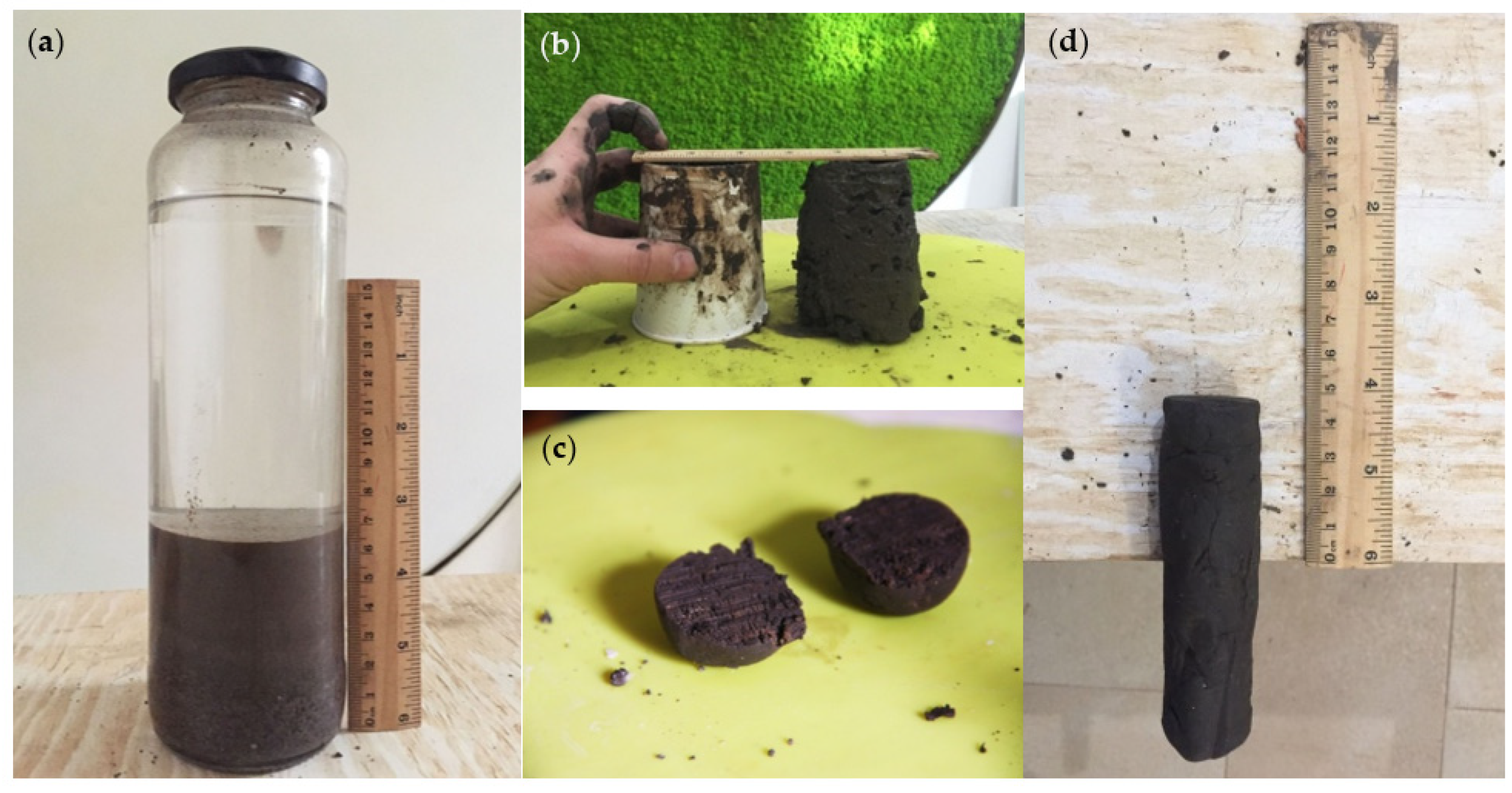
Figure 3.
Grain–size curve of the earth under exam S1; Particle size analysis was carried out on different samples relative to the local soil with starting mass of about 1.7 Kg.
Figure 3.
Grain–size curve of the earth under exam S1; Particle size analysis was carried out on different samples relative to the local soil with starting mass of about 1.7 Kg.

Figure 4.
Comparison between the PSD curves of the soils and the envelopes for rammed earth construction recommended by: (a) Houben and Guillaud [44]; and (b) the Portuguese National Laboratory of Civil Engineering [45].
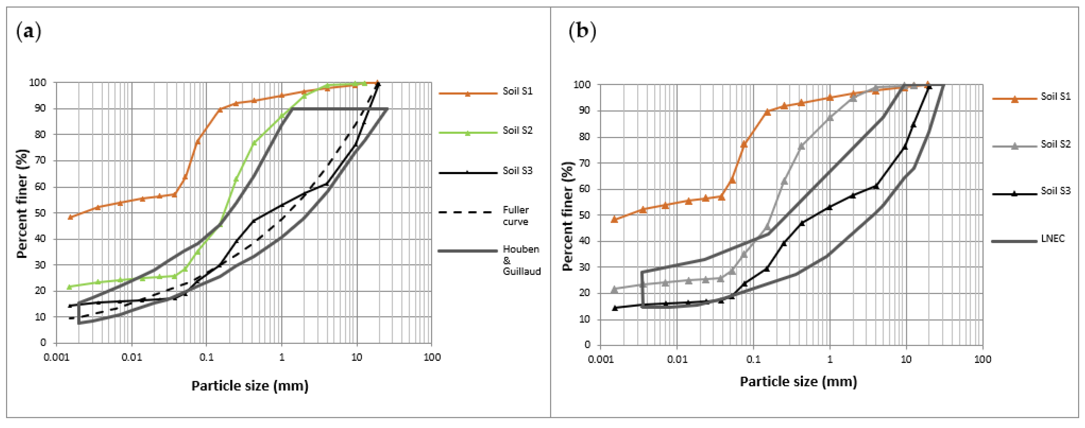
Figure 5.
Proctor test results of the corrected soil S3: (a) results with the saturation curves; (b) standard Proctor test equipment—mold.
Figure 5.
Proctor test results of the corrected soil S3: (a) results with the saturation curves; (b) standard Proctor test equipment—mold.
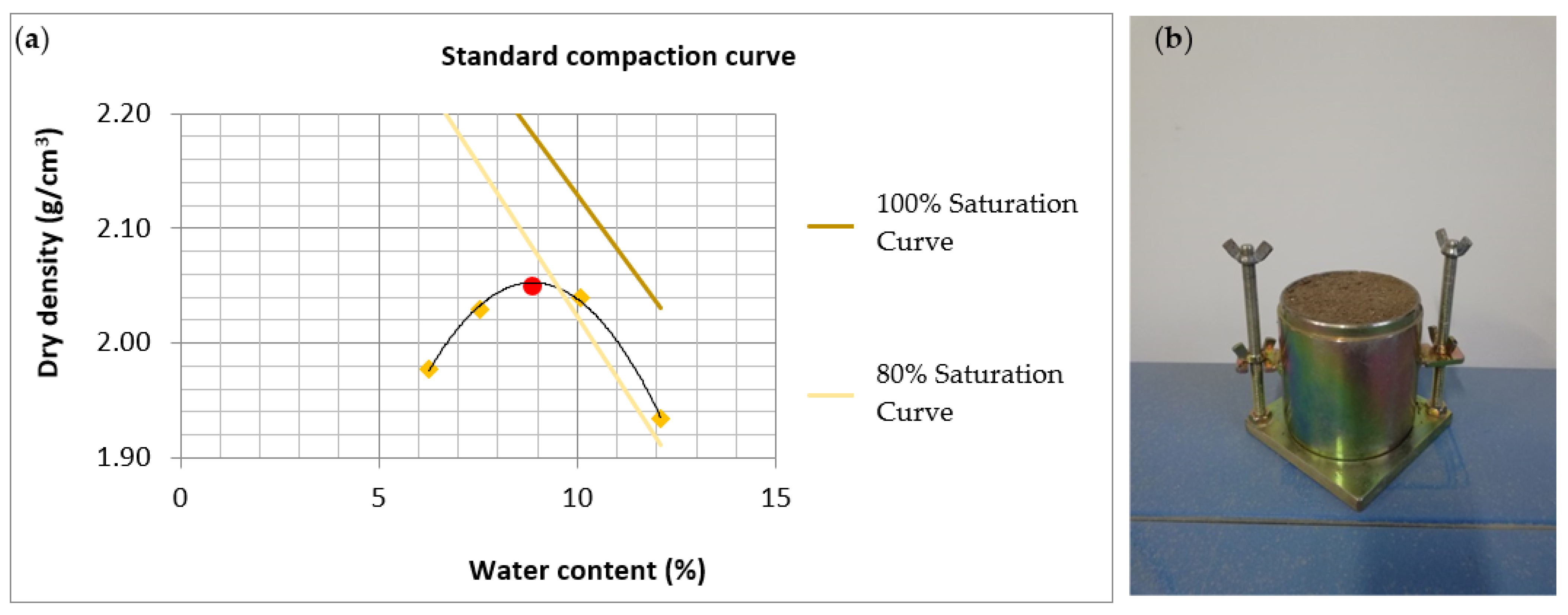
Figure 6.
Cylindrical specimen in beaten earth: (a) top view; and (b) lateral view.

Figure 7.
Failure of the specimens of compression test.

Figure 8.
Stress–deformation plot relating to S3_1–S3_6 cylindrical samples subject to an unconfined compression test.
Figure 8.
Stress–deformation plot relating to S3_1–S3_6 cylindrical samples subject to an unconfined compression test.
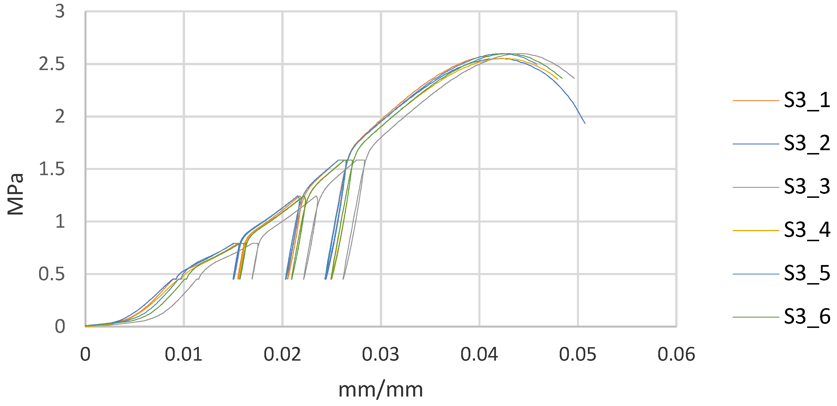
Figure 9.
Compressive strength of S3_1–S3_6 specimens vs. the Young’s modulus.

Figure 10.
Failure of specimens during the indirect tensile test: top view (a); and transversal view (b).
Figure 10.
Failure of specimens during the indirect tensile test: top view (a); and transversal view (b).

Figure 11.
Manufacturing of earth mortar specimens: (a) equipment; (b) earth mortar mix design; and (c) prismatic specimens.
Figure 11.
Manufacturing of earth mortar specimens: (a) equipment; (b) earth mortar mix design; and (c) prismatic specimens.

Figure 12.
Linear and volumetric average shrinkage for M1–M4 mortars vs. the clay content.

Figure 13.
Three-point bending test performed on M1–M4 mortar specimens at the “TecnoLab” laboratory: (a) pre-test; and (b) post-test.
Figure 13.
Three-point bending test performed on M1–M4 mortar specimens at the “TecnoLab” laboratory: (a) pre-test; and (b) post-test.

Figure 14.
Unconfined compression test on M1–M4 mortar specimens, at the “TecnoLab” laboratory: (a) pre-test; and (b) post-test.
Figure 14.
Unconfined compression test on M1–M4 mortar specimens, at the “TecnoLab” laboratory: (a) pre-test; and (b) post-test.


Table 1.
Material properties for rammed earth from the literature.
| Reference | Bulk Density (kg/m3) | Compressive Strength (MPa) | Young’s Modulus (MPa) |
|---|---|---|---|
| NZS 4297- NZS 4298 (1998) [11,12] | nd | >1.30 | E = 300 fc |
| P. Jaquin et al. (2006–2007) [13,14] | nd | 0.60–0.70 | 60 |
| U. Röhlen et al. (2010) [10] | 1700–2400 | 1.50–4.00 | 750 |
| K. Dierks et al. (2000) [15] | 2100–2300 | 2.40–3.00 | 650 |
| Q. Bui et al. (2014) [16] | 1800 | 1.00 | 90–105 |
| M. Hall et al. (2014) [17] | 2020–2160 | 0.75–1.46 | nd |
| D.M. Lilley et al. (1995) [18] | 1870–2170 | 1.80–2.00 | nd |
| V. Maniatidis et al. (2007) [19] | 1850 | 3.88 | 205 |
| V. Maniatidis et al. (2008) [20] | 1850 | 2.46 | 160 |
| L. Miccoli et al. (2012–2014) [21,22] | 2190 | 3.73 | 4143 |
| A. Romanazzi et al. (2019) [23] | 2080 | 1.50 | 471 |
| L. Lacouture et al. (2007) [24] | 1930 | 0.60 | 67 |
Table 2.
Material properties for earth-based mortar from the literature.
| Reference | Bulk Density (kg/m3) | Compressive Strength (MPa) | Young’s Modulus (MPa) |
|---|---|---|---|
| NZS4297–NZS4298 (1998) [11,12] | nd | >1.30 | E = 300 fc |
| M. Van Gorp (2017–2018) [31] | 2140 | 1.40 | 453 |
| Silva et al. (2014) [32] | 1830 | 1.26 | 1034 |
| A. Romanazzi et al. (2019) [23] | 2130 | 1.50 | 471 |
| M. Hall et al. (2014) [17] | 2020–2160 | 0.75–1.46 | nd |
| D.M. Lilley (1995) [18] | 1870–2170 | 1.80–2.00 | nd |
| V. Maniatidis et al. (2007) [19] | 1850–2100 | 2.88 | 205 |
| V. Maniatidis (2008) [20] | 1850–2100 | 2.46 | 160 |
| Domínguez Martínez (2015) [33] | 2210 | 1.50 | 536 |
Table 3.
Theoretical and experimental values of the components in the earth mixture for pisé constructions.
Table 3.
Theoretical and experimental values of the components in the earth mixture for pisé constructions.
| Reference | Clay | Lime | Sand | Gravel | Sand + Gravel |
|---|---|---|---|---|---|
| Füller (1997) [40] | 10% | 14% | 33% | 43% | 76% |
| Van Gorp (2018) [31] | 12% | 13% | 34% | 41% | 75% |
| Houben & Guillaud (2004) [44] | 8–16% | 13–21% | - | - | - |
| Architecturas de terra en Iberoamérica (2003) [41] | 20–30% | - | - | - | 60–80% |
| P. Walker (2005) [46] | 5–20% | 10–30% | - | - | 45–80% |
| Lehmbau Regeln (2009) [47] | 15% | 30% | 15% | 40% | 55% |
| MOPT (1992) [48] | 5–16% | - | - | - | - |
| IETcc (1971) [49] | 10–40% | 20–40% | 10–40% | 10–20% | - |
| Code of Practice SADCSTAN [42] | 5–15% | 15–30% | - | - | 50–70% |
| Standards Australia (2002) [50] | 5–20% | 10–30% | - | - | 45–75% |
| Miccoli et al. (2014) [22] | 11% | 25% | - | - | 64% |
| Doat et al. (1991) [43] | 15–18% | 10–28% | - | - | 55–75% |
| S3 | 16% | 7% | 42% | 35% | - |
Table 4.
The compressive strength values and the Young’s modulus E of S3 specimens.
| N° Specimens | Compressive Strength (MPa) | Young’s Modulus E (MPa) |
|---|---|---|
| S3_1 | 2.48 | 65 |
| S3_2 | 2.67 | 67 |
| S3_3 | 2.59 | 78 |
| S3_4 | 2.47 | 69 |
| S3_5 | 2.58 | 75 |
| S3_6 | 2.67 | 70 |
| Mean Value | 2.58 | 71 |
| Standard Deviation (–) | 0.08 | 4.49 |
| Relative Standard Deviation (%) | 3.10% | 6.32% |
Table 5.
Indirect tensile strength values of S3 specimens.
| N° Specimens | Tensile Strength fct (MPa) |
|---|---|
| S3_7 | 0.212 |
| S3_8 | 0.269 |
| Mean Value | 0.240 |
| Standard Deviation (–) | 0.028 |
| Relative Standard Deviation (%) | 11.67% |
Table 6.
Average characteristic parameters of the analyzed S3 specimen.
| Specimen Characteristic S3 | Value |
|---|---|
| Dimensions | d = h = 150 mm |
| Wet weight | 6000 g |
| Wet density | 2.28 g/cm3 |
| Maximum dry density | 2.07 g/cm3 |
| Compressive strength | 2.58 MPa |
| Young’s modulus (E) | 71 MPa |
| Tensile strength | 0.24 MPa |
| Internal friction angle () | 56° |
| Cohesion (c) | 0.39 MPa |
Table 7.
Compositions of mortars M1–M4.
| Mix Design | Earth | Sand | Clay |
|---|---|---|---|
| S1 | 100% | 0% | 49% |
| M1 | 30% | 70% | 21% |
| M2 | 25% | 75% | 16% |
| M3 | 20% | 80% | 12% |
| M4 | 15% | 85% | 9% |
Table 8.
Linear and volumetric shrinkage of mortars M1–M4.
| N° Specimens | Shrinkage (mm) | |||
|---|---|---|---|---|
| ΔL1 | ΔL2 | ΔH | ΔV | |
| M1_1 | 3.6 | 1.5 | 1.6 | 7.7 |
| M1_2 | 3.3 | 1.6 | 1.6 | 7.9 |
| M1_3 | 3.1 | 1.3 | 1.5 | 7.3 |
| Mean Value M1 | 3.33 (2.1%) | 1.47 (3.7%) | 1.57 (3.9%) | 7.63 |
| Standard Deviation M1 | 0.21 | 0.12 | 0.05 | 0.25 |
| M2_1 | 3.8 | 1.0 | 1.2 | 6.0 |
| M2_2 | 0.9 | 1.1 | 1.2 | 3.2 |
| M2_3 | 0.8 | 1.1 | 1.2 | 3.1 |
| Mean Value M2 | 1.83 (1.1%) | 1.07 (2.7%) | 1.2 (3.0%) | 4.1 |
| Standard Deviation M2 | 1.39 | 0.05 | 0 | 1.34 |
| M3_1 | 0.6 | 0.7 | 0.6 | 1.9 |
| M3_2 | 0.7 | 0.8 | 0.7 | 2.2 |
| M3_3 | 0.5 | 0.6 | 0.5 | 1.6 |
| Mean Value M3 | 0.60 (0.4%) | 0.70 (1.8%) | 0.60 (1.5%) | 1.90 |
| Standard Deviation M3 | 0.08 | 0.08 | 0.08 | 0.24 |
| M4_1 | 0.5 | 0.6 | 0.5 | 1.6 |
| M4_2 | 0.6 | 0.5 | 0.5 | 1.6 |
| M4_3 | 0.4 | 0.5 | 0.5 | 1.4 |
| Mean Value M4 | 0.50 (0.3%) | 0.53 (1.3%) | 0.5 (1.3%) | 1.53 |
| Standard Deviation M4 | 0.08 | 0.05 | 0.00 | 0.09 |
Table 9.
Bending and compressive strength of mortars M1–M4.
| N° Specimens | Compressive Strength fc (MPa) | Bending Strength fct (MPa) | |
|---|---|---|---|
| M1_1 | 1.88 | 3.13 | 0.91 |
| M1_2 | 2.65 | 3.07 | 0.87 |
| M1_3 | 2.13 | 1.97 | 0.98 |
| Mean Value M1 | 2.47 | 0.92 | |
| Standard Deviation M1 | 0.51 | 0.05 | |
| M2_1 | 1.79 | 1.23 | 0.60 |
| M2_2 | 1.89 | 1.25 | 0.69 |
| M2_3 | 1.70 | 1.90 | 0.61 |
| Mean Value M2 | 1.63 | 0.63 | |
| Standard Deviation M2 | 0.28 | 0.04 | |
| M3_1 | 1.33 | 1.11 | 0.51 |
| M3_2 | 1.80 | 1.50 | 0.55 |
| M3_3 | 1.27 | 1.52 | 0.43 |
| Mean Value M3 | 1.42 | 0.50 | |
| Standard Deviation M3 | 0.22 | 0.05 | |
| M4_1 | 0.92 | 1.13 | 0.47 |
| M4_2 | 0.95 | 0.91 | 0.43 |
| M4_3 | 0.71 | 1.16 | 0.35 |
| Mean Value M4 | 0.96 | 0.42 | |
| Standard Deviation M4 | 0.15 | 0.05 | |
Publisher’s Note: MDPI stays neutral with regard to jurisdictional claims in published maps and institutional affiliations. |
© 2021 by the authors. Licensee MDPI, Basel, Switzerland. This article is an open access article distributed under the terms and conditions of the Creative Commons Attribution (CC BY) license (https://creativecommons.org/licenses/by/4.0/).
Share and Cite
MDPI and ACS Style
Sabbà, M.F.; Tesoro, M.; Falcicchio, C.; Foti, D. Rammed Earth with Straw Fibers and Earth Mortar: Mix Design and Mechanical Characteristics Determination. Fibers 2021, 9, 30. https://0-doi-org.brum.beds.ac.uk/10.3390/fib9050030
AMA Style
Sabbà MF, Tesoro M, Falcicchio C, Foti D. Rammed Earth with Straw Fibers and Earth Mortar: Mix Design and Mechanical Characteristics Determination. Fibers. 2021; 9(5):30. https://0-doi-org.brum.beds.ac.uk/10.3390/fib9050030
Chicago/Turabian StyleSabbà, Maria Francesca, Mariateresa Tesoro, Cecilia Falcicchio, and Dora Foti. 2021. "Rammed Earth with Straw Fibers and Earth Mortar: Mix Design and Mechanical Characteristics Determination" Fibers 9, no. 5: 30. https://0-doi-org.brum.beds.ac.uk/10.3390/fib9050030
Note that from the first issue of 2016, this journal uses article numbers instead of page numbers. See further details here.