1. Introduction
The microgrid (MG) has been developed based on the important concept of distributed generation (DG) with high penetration of renewable energy integrated with energy storage systems (ESSs). In MGs, consumers forming parts of the grid invested in DG are able to generate, store, control, and manage a portion of the energy that they consume, resulting in a cheaper and more efficient energy supply solution [
1]. To improve power system security, the distribution network can separate from the main power system and operate autonomously as an island during any unusual phenomena and then reconnect to the main grid if needed. Although the incorporation of technological advancements in digital control into modern communications has facilitated the islanding scheme, it presents challenges related to power quality, protection, out-of-synchronism reclosure, and earthing [
2]. The IEEE standard 1547.4 enumerates the benefits of the islanded operation of MGs: (i) improving reliability for customers, (ii) relieving electric power system overload problems, (iii) resolving power quality issues, and (iv) allowing for maintenance of power system components without interrupting service to customers [
3]. Therefore, autonomous operation subsequent to islanding will be very important in future grids with high DG penetration. Thus, advanced DGs with “plug and play” characteristics should be integrated with distribution systems. These DGs can operate seamlessly in grid-connected mode, islanding mode during the transient-to-islanded mode, and islanded operation, which reduces the chance of a load being unnecessarily excluded from the island and permits maximum flexibility of the multi-islanded system. The future power system can robustly respond to any fault occurring within by dividing itself into several islanded entities without stopping the DG operation. This paper focuses on such separated multi-islanded entities and their seamless reconnection as a self-healing ability of the future power system. Controllers with/without intercommunication mitigate power quality problems in these entities, and, eventually, the consumers will receive continuous power of high quality.
2. Flexible Operation of the Future Power System
Renewable energy (RE) has received attention worldwide due to its fantastic advantages: it is a cheap/free fundamental fuel with no emissions. In particular, the 2011 Fukushima nuclear disaster necessitated the use of RE to compensate for the lack of power after shutting down Japan’s nuclear reactors and the sudden increases in CO emissions. With the high DG penetration of the distribution power system, cost and reliability constraints may motivate a multi-functional power electronic interface (PEI) for DG, where a single DG unit can perform many tasks, such as identifying and preventing potential trends, islanding detection, synchronizing to the main grid, and black start operation. Also, it is characterized by voltage ride-through capability, self-adaptive control, the power quality of islanded entities, the flexibility to integrate DG by management and control, etc. Therefore, a reliable islanding detection method and a powerful PEI of DG will contribute to boosting the “proactive DG grids” concept.
2.1. Multi-Agent System for the Energy Internet
As stated in [
4], the concept of the “Energy Internet”, as in
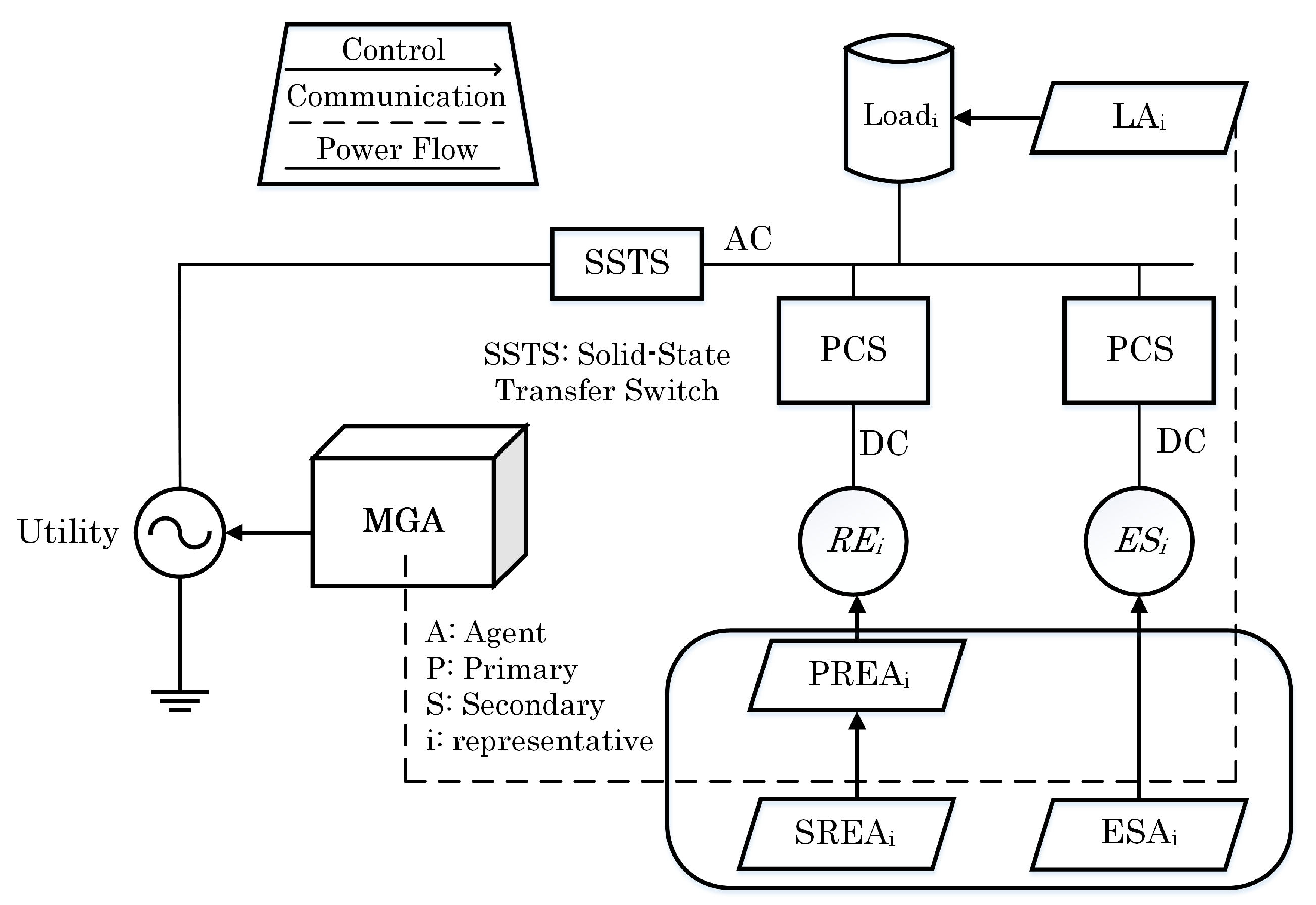
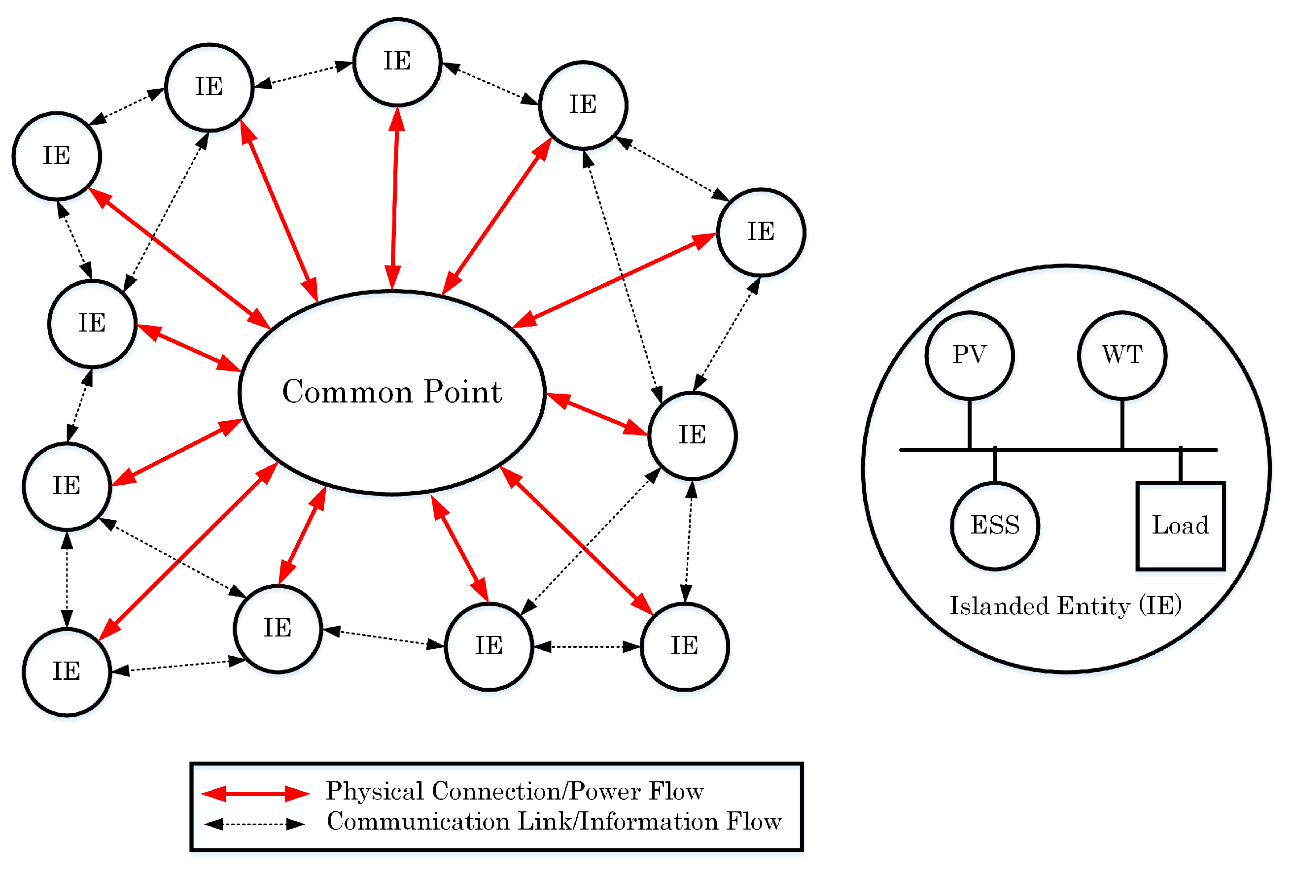
Figure 1, has been recently proposed. The components of the Energy Internet consist primarily of RE, ESSs, and other parts of generations, which are not mentioned here. The Energy Internet has the ability to operate in either the grid-connected or islanded mode. High RE penetration will inevitably change the way power flows, transitioning from passive to active generation. In
Figure 1, the Energy Internet is isolated and cut off from the power supply due to a fault that occurred on a feeder which resulted in the opening of solid-state transfer switch (SSTS). The isolated entity can be reconnected with the utility once any RE is closed during the isolated period running as in an autonomous operation. The critical design and control objectives of the Energy Internet during this mode are: (i) maintaining flexible and proportional power-sharing among REs; (ii) maintaining the system’s continuous synchronization with the utility in the presence of load variations; (iii) minimizing circulating currents between DGs; and (iv) achieving seamless energy transitions between the Energy Internet and the utility if necessary. The conventional power system uses the supervisory control and data acquisition (SCADA) system to exchange status and control signals of components. This centralized SCADA system was originally designed for traditional passive networks; it thus may be inadequate to cope with complex control decisions because it lacks flexibility and extensibility [
5]. The designation of the controller structure used in an Energy Internet is based on the “multi-agent system” (MAS) structure, wherein a different agent controls each component. The MAS helps monitor and control the new complex power system. In the MAS, one centralized control is separated into simpler single entities that work in collaboration pursuing assigned tasks to achieve the overall goal of the system. It is a system based on the advantages of the agents’ properties: flexibility, scalability, autonomy, sociality, reactivity, proactivity, and reduced complexity. Under the control of the MAS scheme, the power system performs demand-side management to secure critical loads, shedding low-priority loads in severe cases. Various RE units and other components of the grid communicate with the islanded entity through the IP-based local control model (IP = Internet Protocol). The entity disconnects itself from the utility and operates autonomously to maintain the integrity of the system.
Figure 1 shows three different agents designed for the distributed coordinated controller, including the upper-level coordinated control strategies, MG agent (MGA), and the RE agents (REAs). An REA, comprising a primary REA (PREA), secondary REA (SREA), and energy storage agents (ESAs), implements local decentralized continuous control. The MGA executes its functions according to information provided by all agents, and tasks are implemented by sending logic control commands to the unit control agents through a master/slave communication mode. The MGA is also called the energy router and is used to regulate the power flow between the Energy Internet and the utility. The ESA and SREA together are called the energy switcher, which is used to regulate the power flow within the Energy Internet. Also, to improve the Energy Internet management, load agents (LAs) should also be considered. The Energy Internet operates under two modes: (i) the utility-connected mode, in which the stiff utility compensates for power unbalance within the Energy Internet; (ii) the isolated mode, in which one of the DGs or REs should be chosen as the control master. Advanced droop control is distributed to implement proportional power sharing among DGs in the Energy Internet as a primary control. Then, a secondary control via a centralized or distributed method is added to restore the voltage and frequency to nominal values. The centralized control, which requires proper communication systems to realize the control goals, sometimes presents a single point failure. In such a scenario, the MAS acts as a kind of distributed control structure to make control decisions for each DG according to its neighbor’s information, demonstrating its flexibility for faster and computational efficiency.
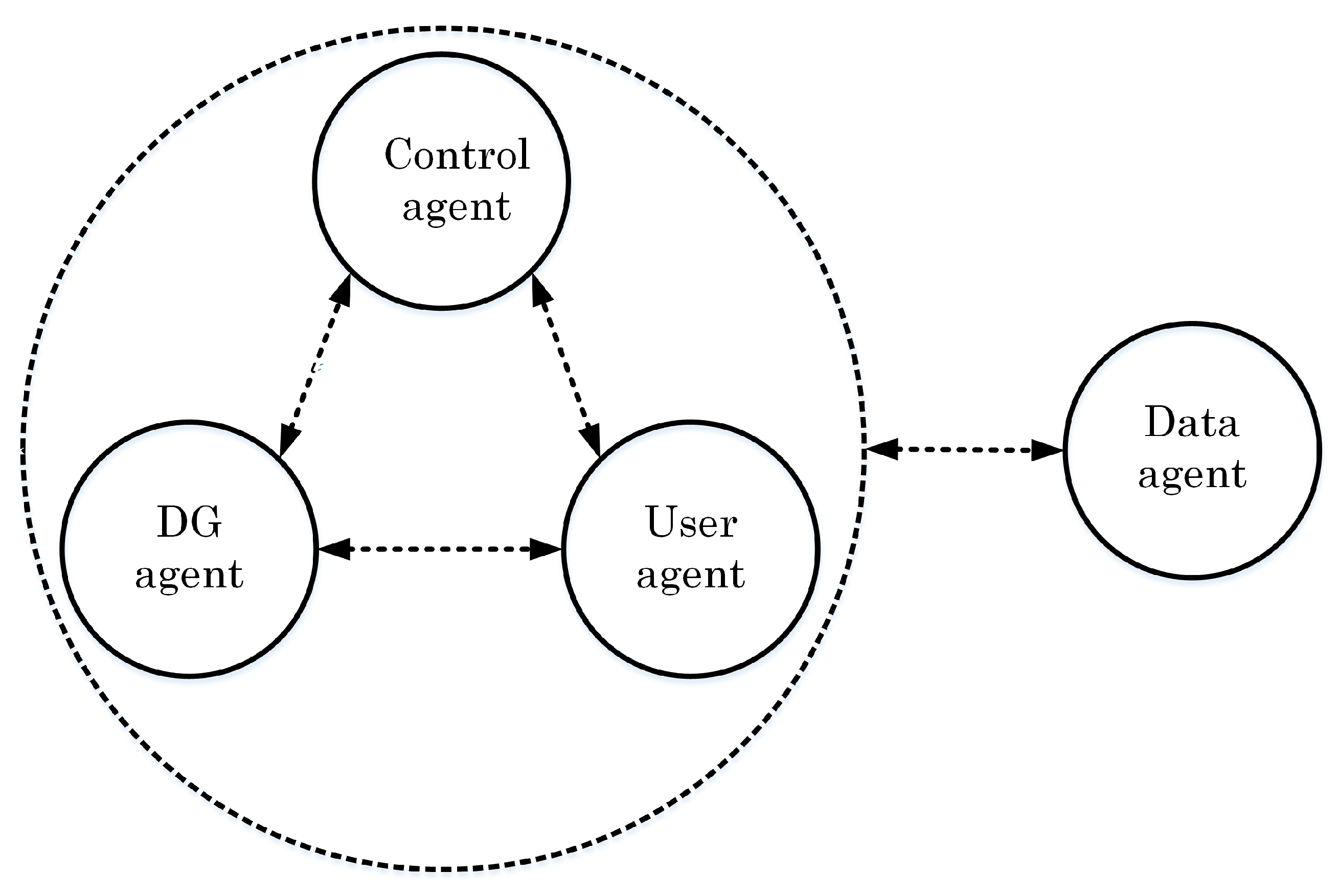
Another approach is presented in
Figure 2, which shows the architecture of an MAS. The MAS comprises four types of agent, namely, a control agent, a DER agent, an additional user agent, and a database agent. Each agent has a unique objective and responsibility, as defined explicitly in [
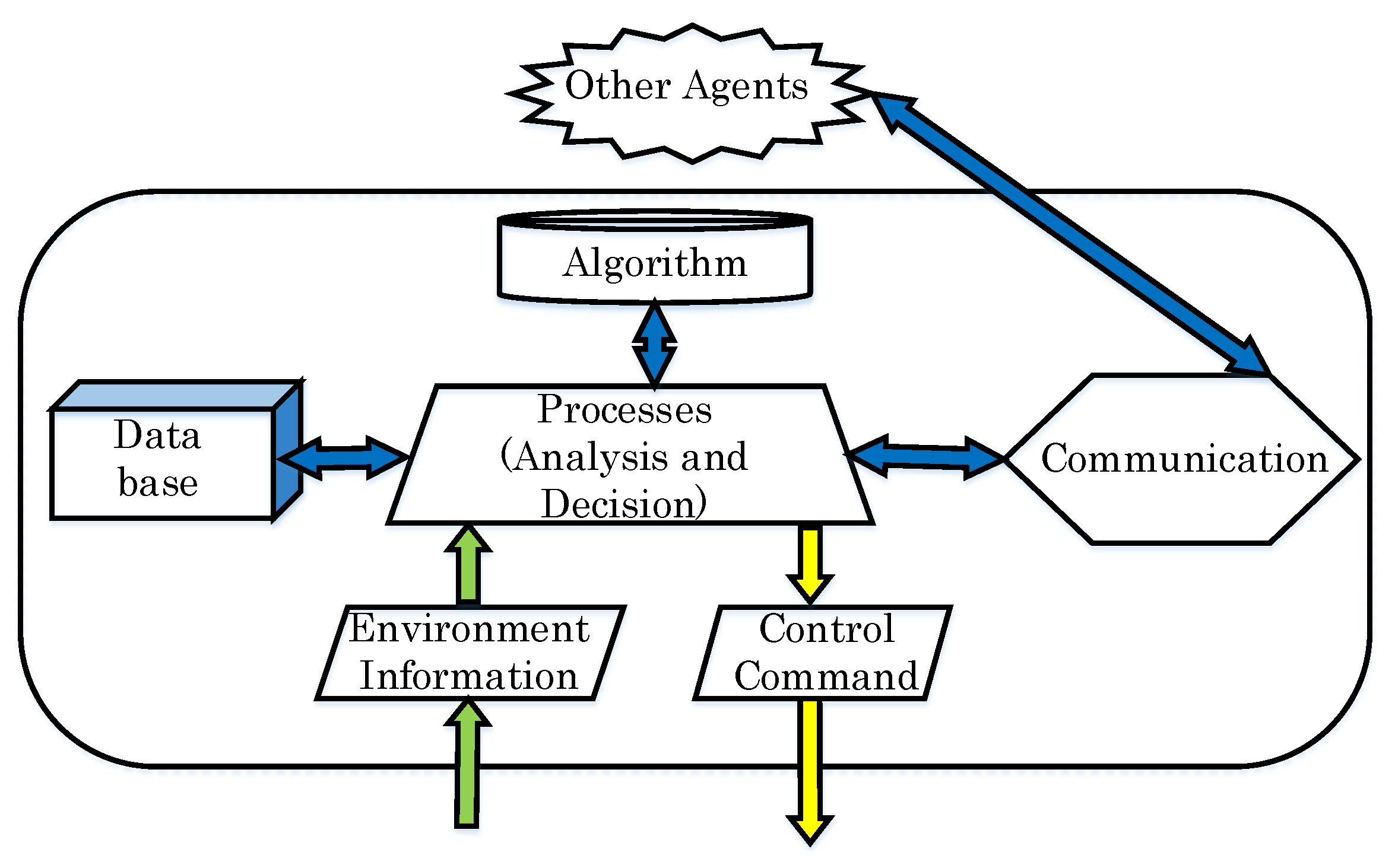
6]. The principle of agent structure is presented in
Figure 3 [
7]. According to information which is external to the agent, the agent management creates a database, processes these data, and then outputs a control signal to its components regarding the response from the other agents.
An event-triggered hybrid control for the Energy Internet was proposed in [
8]. In this paper, by developing an MAS-based event-triggered hybrid control scheme, the Energy Internet could comprehensively use the RERs when encountering load demand with high security. The MAS could be used to implement hierarchical hybrid control in a coordinated way based on four types of control strategies, such as hierarchical load shedding and the hierarchical switching control of RERs, designed as event-triggered functions (ETFs), or local switching control and distributed dynamical control, designed as constraint violation functions (CVFs), which are completely dependent on the logical resource-grid-load-storage relationship.
2.2. Flexible Operation
With the general theme “Flexible islanded operation of proactive DG grids”, the DG unit can operate seamlessly in the grid-connected mode (by current control), islanding mode during the transient-to-islanded mode (by energy storage), and islanded operation (by droop control) [
9,
10,
11]. Autonomous operation subsequent to islanding will be very important in future DG grids [
12,
13,
14,
15,
16,
17]. The desired PEI-DGs with “plug and play” characteristics should be integrated into distribution systems. As a result, the whole power system can robustly respond to any fault occurring within by dividing itself into several islanded entities without stopping the DG operation. With DGs, in order to fulfill these goals, the PEI plays the main role in control. Power electronic equipment reacts very quickly, which can overcome severe transient events. Thus, besides interfacing with utility grids, PEIs have the potential to mitigate power quality problems (such mitigation includes active filtering, voltage unbalance compensation, grid support, and ride-through control under voltage dips, among other functions) and carry out other duties, such as identifying and preventing potential trends.
Recent approaches focus on separated multi-islanded entities and seamless reconnection to continuously supply power of high quality. It is not only self-control conducted without intercommunication [
18,
19]; some PEI-DGs of the DG grid are to be managed using a central controller linked by communicated signals [
2,
20,
21]. Then, the power system operating with DG should emerge as a convergence of electrical, information, and technological engineering. Three operation modes of the DG grid are discussed herein, as follows:
Grid-connected mode: To a large extent, grid-connected mode system dynamics are fixed by the utility because of the small size of the DG units. MGs aim to satisfy demand by local DGs. Excess or deficient active and reactive power in an MG can be absorbed or supplied by the utility grid, respectively.
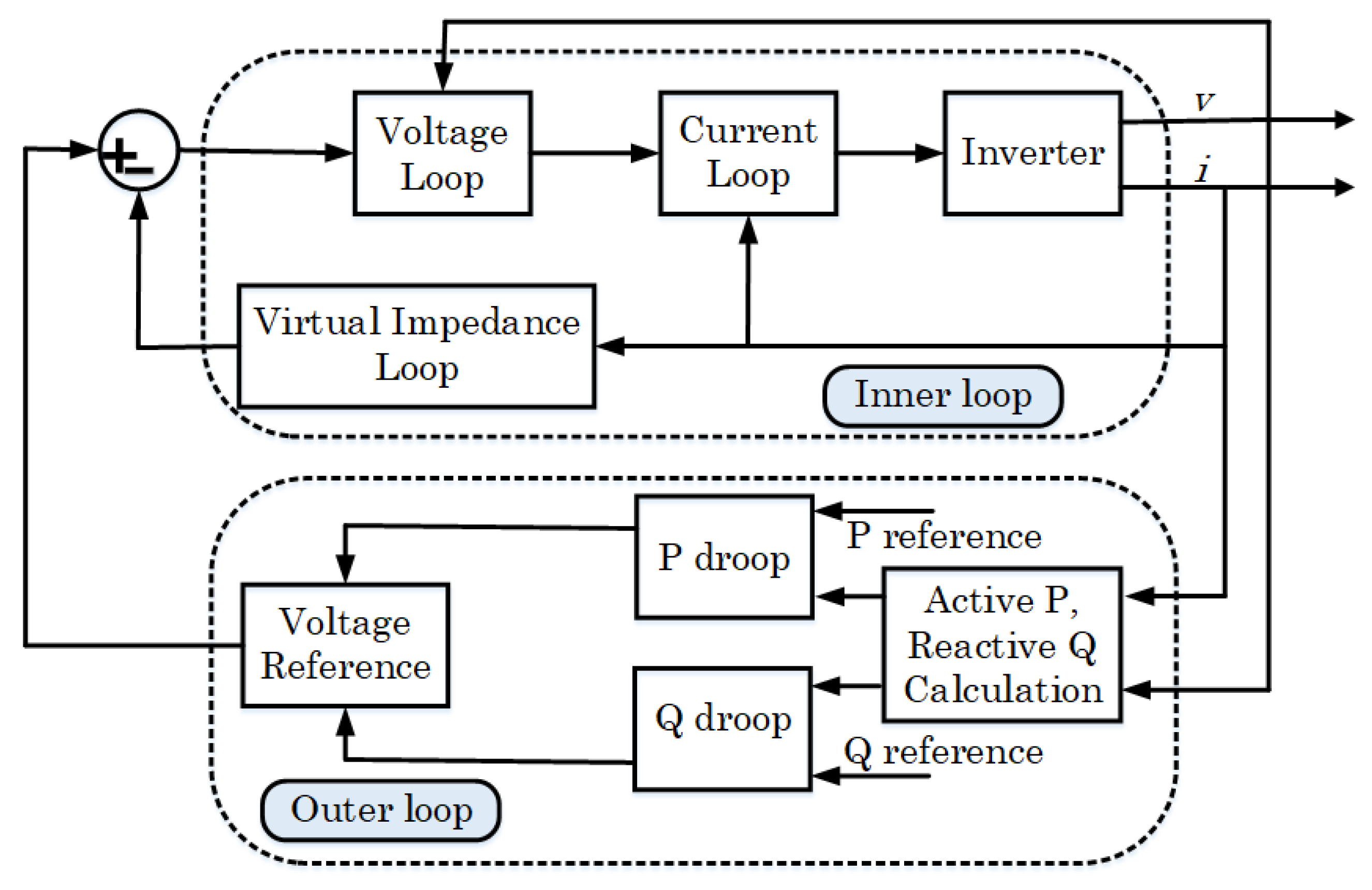
Autonomous/islanded operation mode: The disconnected scenarios include intentional (e.g., maintenance or detection of a permanent fault) and unintentional disconnection (e.g., blackout due to disconnection from the utility). In this mode, the system dynamics are depicted by its own DG units. The power balance within the islanded entity between generation and demand must be observed to maintain system frequency and voltage within acceptable limits and ensure stability. Reactive power compensation and harmonic current are shared within an islanded entity by applying droop control to DGs. The virtual impedance method as an advanced technique is further used to reduce active power control errors, enhance fast dynamic control during the transient, and minimize the circulating power among controllers, as seen in
Figure 4.
Transient mode: into-islanded and back into-utility: Power balance should be provided by power storage systems, such as batteries, super-capacitors, or flywheels. An intelligent bypass switch (IBS) [
12] continuously supervises both grid-connected and islanded modes. When the IBS detects that maintenance is needed or a fault is present at the utility side, the islanded entity must be disconnected, and then a restoration process is activated to ensure high reliability. The IBS can detect the main grid’s fault-free stability and synchronize voltage amplitude, phase, and frequency, which are utilized for the reconnecting procedure. In the event that islanded mode is forced to run for a long time, synchronization of voltage, frequency, and phase between islanded entities and the utility is implemented to seamlessly reconnect after an approximate zero-point reclosing of smooth and soft synchronization.
2.3. Hierarchical Control
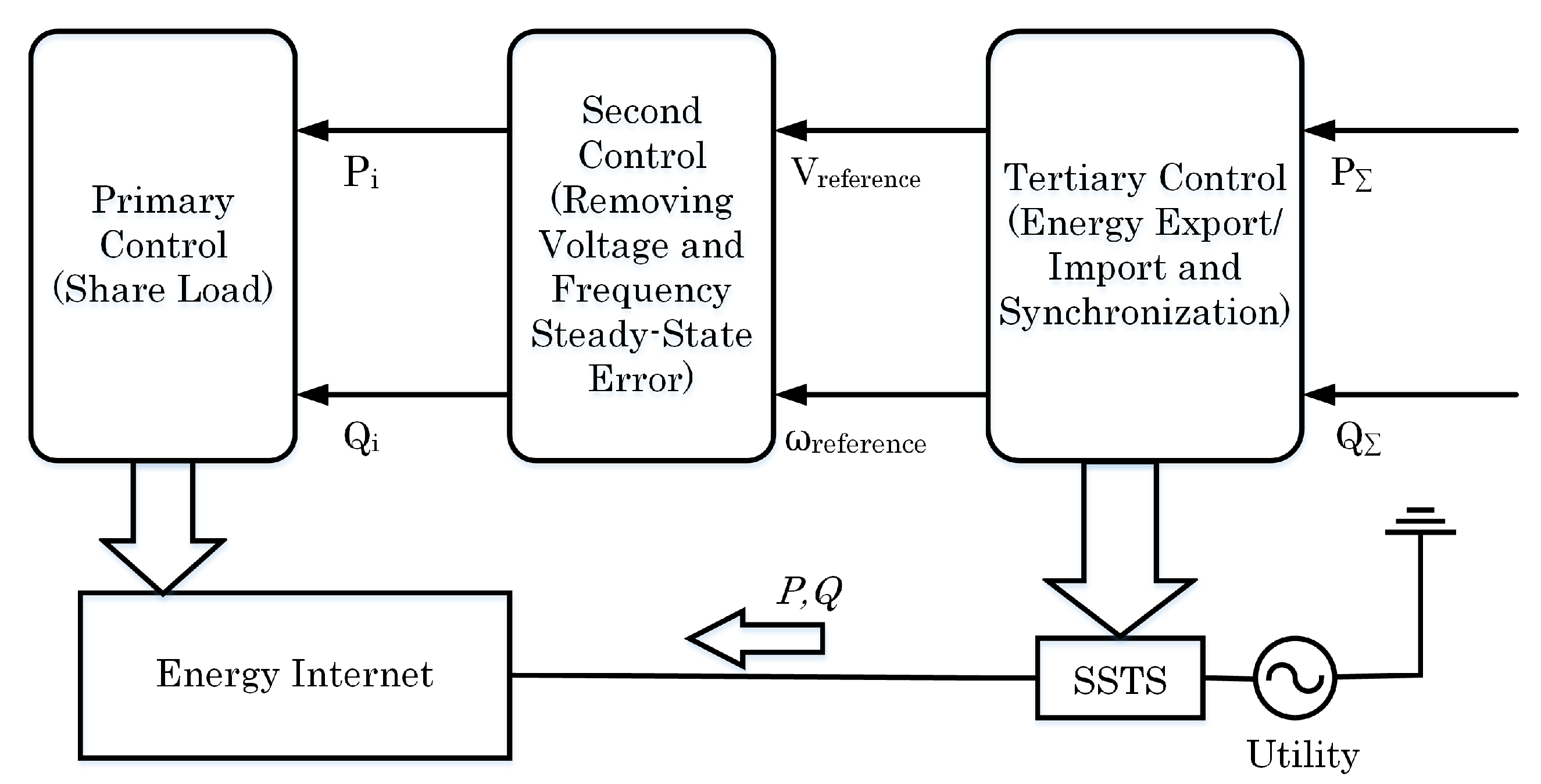
Hierarchical control of islanded entities basically includes three main levels [
12,
22]. Primary control is the droop control used to share loads between PEI-DGs in order to adjust the islanded frequency or amplitude output voltage, as seen in
Figure 5 hereafter. Local controllers in DG are operated primarily for speed and reliability. Secondary control is responsible for removing any steady-state errors imposed by the primary control to guarantee the stabilization of voltage and frequency for loads. It links all of the DG’s controllers to let the system respond consistently in wider areas. Power flow modeling of droop-controlled distributed generation units with secondary frequency and voltage restoration control for hierarchically controlled islanded microgrids was introduced in [
23]. Tertiary control, which involves more global responsibilities, determines the import or export of energy among islanded entities to compensate for voltage harmonics in the point of common coupling (PCC) and generates synchronization loops to transfer from islanded mode back to grid-connected mode. A simple illustration of the three-level hierarchical control is in
Figure 5. All DGs in the hierarchy respond to disturbances as one set or, in the most appropriate manner, all DGs respond to a disturbance, and there will be a speedier return to a stable synchronous islanded operation. However, the whole control system must be resilient to a telecommunication delay and be robust to temporary communication outages. The communication bandwidth chosen for the entity is a compromise between the amount of data that is transferred along the network infrastructure and the transient response that is required from the secondary control loops. A high data bandwidth implies a fast transient response for the secondary control loops while providing a high data transfer rate along the network. Since the restoration of the voltage and frequency of the MG are noncritical, bandwidth communications of as low as 1 Hz can be used to achieve the required functionality.
2.4. Load Sharing without Communication—Droop Control
As one level of the hierarchical mechanism, droop control concepts have been widely adopted to provide decentralized power-sharing control between DGs without relying on communications. Assuming the line is mainly inductive, the
P-f and
Q-V droop strategies provide stable active and reactive power sharing. However, in a low-voltage distribution system, where the X/R ratio is small, especially for transformer-less inverters that have very small output inductance, droop control is subject to real and reactive power coupling and steady-state reactive power sharing errors. Additional compensation schemes for the traditional droop control, such as opposite droop, virtual inductance, average power control, or virtual impedance compensation, have been proposed for accurate power control [
20]. Moreover, in addition to droop control, communication can be used as a noncritical element in a higher control layer, such as the secondary control of the hierarchical structure, to enhance the performance of the islanded entities without reducing system reliability. Therefore, each DG unit should have the ability to exchange information with the central energy management system (EMS) to receive the reference values through a communication link.
Although the
P-f droop technique can achieve accurate real power sharing, voltage droop control
Q-V commonly results in poor reactive power sharing. This is due to the mismatch in the voltage drops across the DG unit feeders, which is induced by the mismatch in the feeder impedances (virtual output impedances of the closed-loop voltage controller of the DG units or feeder physical impedances, including the transformers, cables, and interface reactors, or even the variation of droop slope
) and even the differences in the power ratings of the units. The time delays in communications may also significantly reduce the reactive power-sharing accuracy, which can also be affected by lost communication [
24]. A complex configuration of an entity (looped or mesh networks) will also make reactive power-sharing more challenging and often degrade not only the voltage but also frequency quality due to a harmonic injection. In one study aiming to solve the reactive power-sharing problem [
19], small real-reactive power coupling disturbances (the real and reactive power are coupled together for frequency and voltage droop control) were injected to obtain accurate reactive power sharing before automatically switching back to conventional droop control. This method is effective for all types of configurations, and detailed structural information of these entities is not needed to achieve the “plug and play” operation of DGs and loads.
Two new problems need to be solved immediately in a cascade-type microgrid: the synchronization and power balance of distributed generators. An
f-P/Q droop control strategy is proposed in [
25] to solve this problem. This proposed droop control can achieve power balance under both resistive-inductive and resistive-capacitive loads autonomously. It has a clear advantage in extending the scope of application compared with the inverse power factor droop control.
2.4.1. Conventional Droop Control
In the grid-connected mode, the supply–demand balance of an MG is less restrictive since the grid behaves like a large energy reservoir for buffering any mismatches between the power supply and load demand. The buffering effect is, however, not available in the islanded operation mode, which requires a stricter supply–demand balance. Also, a load-sharing function among the DGs is needed to avoid stressing a particular DG. As a result, the control of DGs needs a decentralized technique (i.e., droop control), which is tuned according to the individual DG rating. The operation of DGs relies only on locally measured quantities and, hence, does not require communication links [
26].
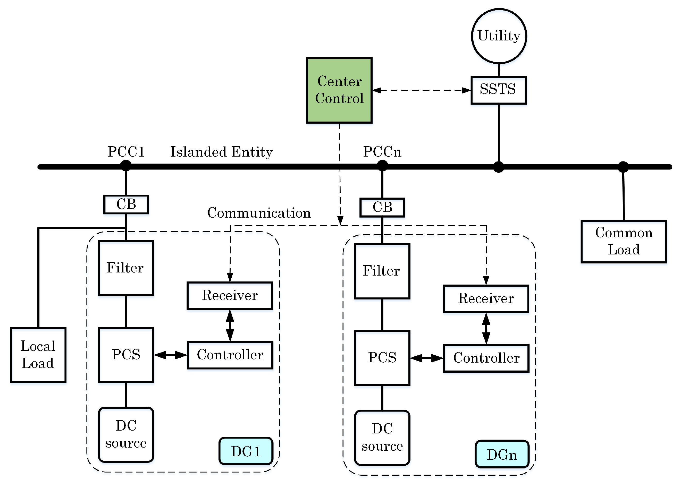
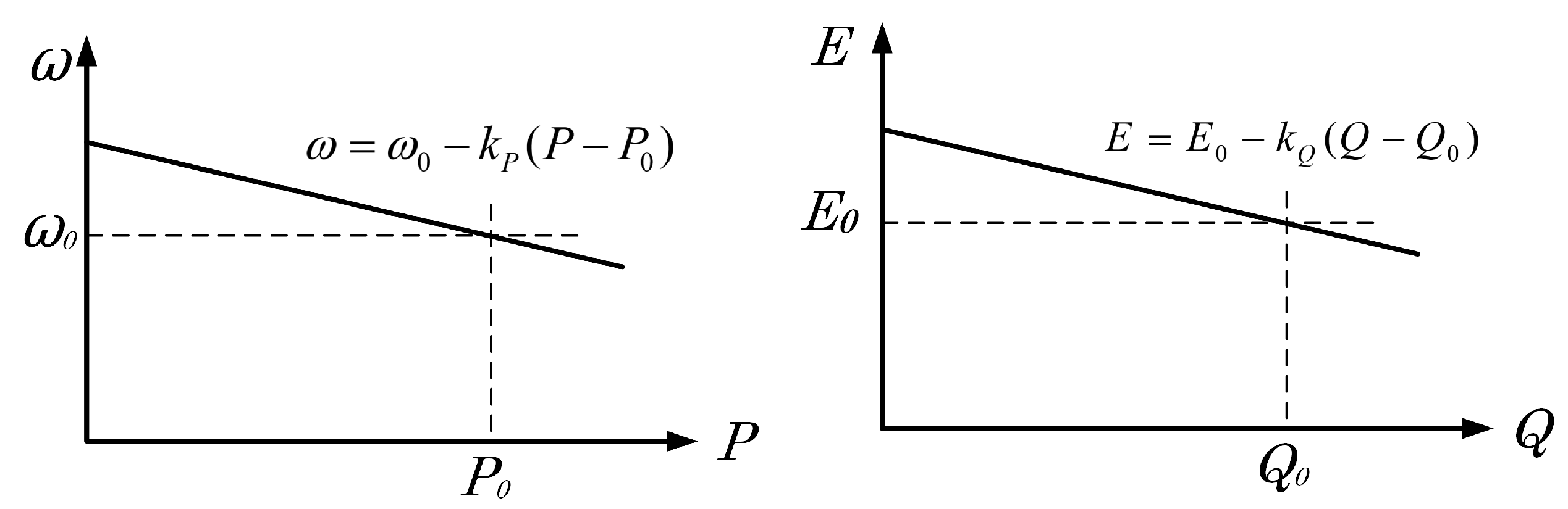
Figure 6 shows the typical configuration of an MG which consists of a number of REs or DGs and loads. Each DG is interfaced to an MG with a power conditioner system (PCS) consisting of an inverter, which then connects to a common AC bus by its own feeder. A central controller monitors the status of all components inside this MG to decide whether to operate in grid-connected mode or islanding mode by controlling the SSTS at PCC. While in the grid-connected mode, real and reactive power references are normally assigned by the central controller, and conventional droop control can be used for power tracking. The deficient or excess power can be easily compensated for by the utility. Then, typically, DG will generate its maximum power, and power sharing is not a concern in this mode. In the islanding mode, the total load demand must be properly shared by the DG units within the islanded entity by applying two well-known mechanism-based equations, as seen in
Figure 7:
where
and
are the nominal values of DG angular frequency and DG voltage magnitude;
P and
Q are the measured real and reactive powers;
and
are the real and reactive power droop slopes.
2.4.2. Advanced Droop Control
Since conventional droop control faces several drawbacks in term of sharing accuracy, improved droop techniques have been proposed by many papers, year after year. In [
18], a three-layer control scheme was proposed for inverters operating in parallel without intercommunication. In [
7], the droop control method is proposed as a good solution to the outer loop power controller in an MG. However, the method itself is not suitable for the upcoming flexible MG. The inner loop controller (PI controller, robust controller, prescribed performance) ensures that frequency and voltage deviations are regulated robustly toward zero after every change in load or generation inside the MG. When nonlinear loads exist, besides balancing active and reactive power, controlling that load sharing is a challenge. Thus, harmonic-current-sharing techniques have been proposed recently to avoid the circulating distortion power that occurs when sharing nonlinear loads. Novel control loops that adjust the output impedance of the units by adding output virtual reactors or resistors have been included in the droop method with the purpose of sharing the harmonic-current content properly [
1]. Further, by using the droop method, power sharing is affected by the output impedance of the units and the line impedances. Hence, these virtual output-impedance loops can also solve this problem. In this sense, the output impedance can be seen as another control variable [
1]. In case of paralleling DC power converters, the droop method consists of subtracting a proportional part of the output current from the output voltage reference of each module. Thus, a virtual output resistance can be implemented through this control loop. This loop, also called the adaptive voltage position, has been applied to improve the transient response of the voltage regulation modules in low-voltage high-current applications. In addition, the droop method has an inherent trade-off between voltage regulation and current sharing between the converters. To cope with this problem, an external control loop, named secondary control, has been proposed to restore the nominal values of the voltage inside the MG. Further, additional tertiary control can be used to bidirectionally control the power flow when the MG is connected to a stiff utility (in the case of AC MGs) [
1].
2.5. Intelligent Controlled Islanding Scheme
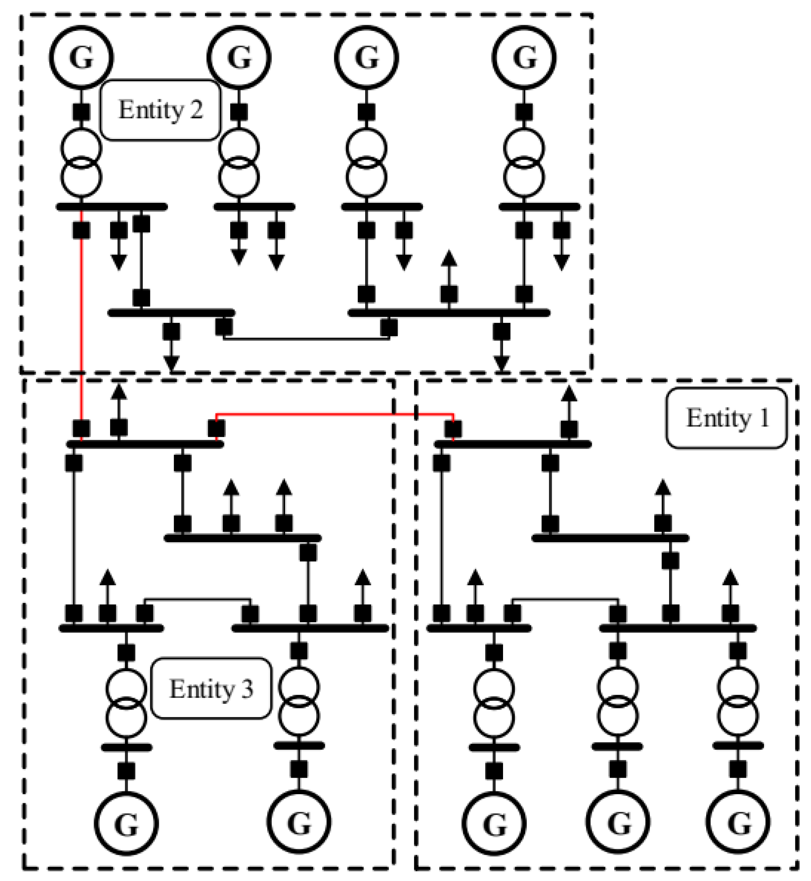
During stressed conditions of power systems, such as peak load periods, a fault can cause cascading problems that lead to grid collapse. To prevent a blackout, a power system can be intentionally split into separated self-healing islanded entities that await a reconnection condition. However, to establish an effective islanding scheme, many obstacles need to be overcome. Islanding locations, time of disconnection, and the moment to reclose based on the network’s operating topology or local relays are determined coordinately. The aim is to stabilize each islanding at the highest power balance, considering generator coherency. This configuration, where the number of islanding entities is known ahead of time, could facilitate autonomous operation within each entity. In a study by [
27], one islanding execution algorithm and topology was performed. The procedure for determining the time of islanding is performed at three different points: offline, online, and in real-time. The number of stable islands with appropriate security levels is pre-determined by monitoring the dominant inter-area oscillations between the initial groups (IGs), as depicted in
Figure 8.
For the MAS, to exchange information and to coordinate control, the entities are connected tightly in a cyber-communication network [
28]. In the autonomous operation mode, each entity operates independently by controlling DGs, ESSs, and loads for economic and self-adequate objectives. Ideally, no information exchange or power flow exchange is needed among MGs. When a fault occurs in an entity, it receives power support from another entity in the self-healing mode. There are two layers in the cyber-communication and control network. The lower layer is in the entities to control DGs, ESSs, and loads locally, while the upper layer communicates with neighboring counterparts by broadcasting its power support request or response to other requests to obtain actual aggregated support until the fault is cleared to achieve overall reliability.
Figure 9 shows autonomous networked MGs. The network consists of both strong cyber-links for communication and physical connections via a common point for power exchange. The connection could be a DC line to separate each MG completely.
2.6. Role of ESS in Islanded Entities
Technically, controlling autonomous islanded entities is complicated. Due to its small physical inertia, even a small interruption, such as the output power fluctuations of photovoltaics (PVs) or wind turbines (WTs) and switching in/out of loads, may lead to voltage and frequency problems or MG instability. With the crucial presence of an ESS, the frequency and voltage of an entity can be maintained stably through an appropriate ESS controller by flexibly releasing or absorbing active/reactive power. For a small entity, one ESS as a constant voltage/frequency source can manage MG operation. With the larger entity, where many ESSs exist, coordinated control is relatively complex. Droop control for an ESS has been considered a solution in recent studies. The voltage angle and amplitude of each ESS are regulated according to their output active and reactive power, respectively. Therefore, the active/reactive power can be shared according to a preset droop coefficient among the parallel ESSs. Unfortunately, since the real and reactive power coupling among ESSs is due to a predominant resistive MG, the control scheme is more difficult. As mentioned, advanced virtual output impedance methods could enhance load sharing, but it reduces the control bandwidth, resulting in deterioration of the system dynamic stability. Also, combining the traditional
V/f droop control (VFDC) with
P/Q droop control (PQDC) to prevent the interference of line impedance uncertainty could enhance current sharing among ESSs and system dynamic stability. An energy management system combined with hierarchical control based on smart communication for droop gain optimization also can be used to improve the quality of voltage/frequency with secondary and even tertiary control. However, the dependence on communication will lead to another problem, such as increased cost and decreased reliability [
29].
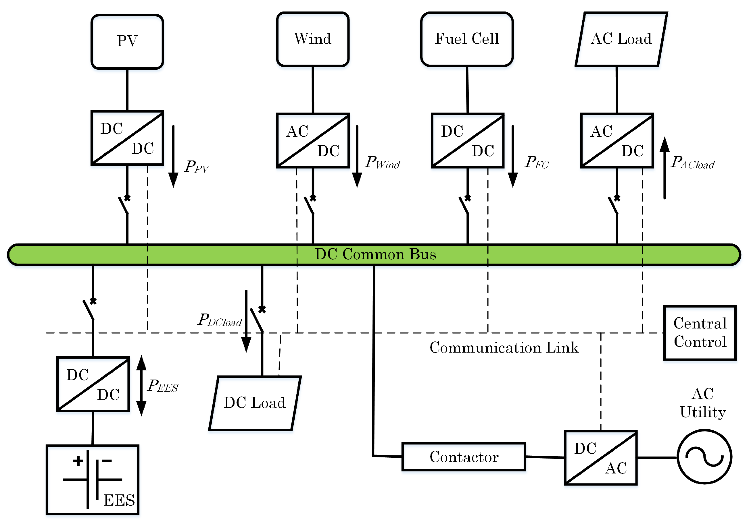
DC MGs have recently drawn great attention for applications such as building electrical systems, data centers, and plug-in hybrid electric vehicles, due to their higher efficiency than AC MGs, their flexible control capability, and the convenience of integrating DC resources and loads. A schematic of a DC MG with the integration of RESs, battery energy storage systems (BESSs), and loads is shown in
Figure 10. During autonomous operation, an ESS unit is also utilized in a DC entity to compensate for the power fluctuation between power generation and consumption. Bidirectional DC/DC converters are used to control the output of battery banks. RESs, including solar PV and wind turbine generators, are integrated through DC/DC and AC/DC converters, respectively. RES converters normally operate in a maximum power point tracking (MPPT) mode to harvest maximum renewable sources. A bidirectional DC/AC converter as a link converter is used to interlink the utility with the DC bus. A contactor at the DC side can be installed between the link converter and the DC entity to control their connection. A contactor is an electrically controlled switch used for switching an electrical power circuit, similar to a relay except with higher current ratings. The functionality and control method of the contactor is similar to that of an SSTS at the AC side in conventional AC entities. The contactor is closed in the grid-connected state and opened during islanded operation in case of a utility grid fault. The linked DC/AC converter monitors the AC-side power quality (voltage magnitude, frequency, phase unbalance) to enhance the system’s response speed.
In an islanded DC entity, a coordinated energy management strategy, such as hierarchical control, should be used for power balance to prevent the ESS from overcharging and over-discharging. The state of charge (SOC) of an ESS is therefore monitored. Depending on different SOC scenarios, the coordinated operation of a DC islanded entity is achieved by managing all power flow from RESs, ESSs, and loads. The hierarchical structure is responsible for this coordinated control based on a reliable communication link. Under hierarchical control, the lower control level receives commands from the higher control level to take action. The secondary controller regulates the bus voltage at the nominal value. The central controller makes decisions based on the SOC condition of the ESS units collected from the primary level and then sends control mode signals to the other units. When one ESS is not fully charged, it is operated at the maximum power point (MPP) to utilize renewable energy effectively. On the other hand, the controller limits the input power of an ESS unit when it is fully charged. Simultaneously, RES units reduce their power output. When an ESS discharges during high power consumption, RES units should operate at MPP. In cases where it is unavoidable, noncritical load shedding can be conducted when power consumption is too high [
30].
In the islanded mode, ESS units operate in voltage regulation mode and a linked DC/AC converter operates in the idle mode. In term of the return-to-utility state, the voltage quality of the utility is first checked at the central controller to ensure the disturbance has been cleared. When it has met the criteria, the signal for disturbance clearance is sent to the central controller through the SCADA. The link converter is activated to regulate the DC-side output voltage. It is checked again until the parameters are satisfactory. The voltage difference across the contactor should be minimized before the contactor is closed.
3. Future Perspective of Power Systems with High DG Penetration
Recent smart MGs are run based on small WT and PV sources, ESSs, and distributed loads which are connected to the PCC of the utility through the intelligent bypass switch (IBS) or the conventional SSTS. The overall system consists of a number of REs that require power electronic inverters. Because of the high penetration of REs, the integrated power system with a complicated physical connection and multi-layer cyber-link might easily suffer cascading outages. Faults may have conventional causes, such as a short circuit, lightning, or huge load changes; faults may also have unconventional causes, such as a natural disaster or terrorist attack. Some recent research efforts with advanced technologies are trying the address these problems: load forecasts to adjust the power balance during the day is a key power-saving solution which enables smart power communities [
16]; a distribution network with residential DG units should be actively made more flexible and dynamic where bidirectional power flow occurs, as new reconfigurations could be frequently observed [
17]; a networked communication, computation, and sensing system facilitates all robust controllers to make the grid more secure, efficient, and reliable by quickly responding to any abnormal phenomenon based on adaptive self-healing and self-organizing mechanisms [
13].
To build a robust power system with high RE penetration, the main idea is to connect many reliable MGs to the main grid or interconnect them through tie lines, thus forming MG clusters. This can make the control bulk system simpler, similar to the scheme in
Figure 9. Each cluster is defined clearly, and the data of that cluster are sufficient and compensated whenever any new components, such as DGs or loads, are installed. The maximum number of elements within one cluster should be determined for easily handling tasks. In the distribution grid, to guarantee that the voltage of terminal loads is within limits, the number of elements from the substation cannot be too high. The conventional power system will be divided into many clusters. If a DC tie link cannot be made, the substation can be considered the common coupling point of one cluster. In the future grid, with more smart elements and sensitive load increases, cyber-attacks will increase, and the switch of elements will frequently occur. Also, the current configuration of the power distribution system can lead to a cascade fault and blackout. A fundamental MG can be defined as a part of the grid consisting of prime energy movers, power electronics converters, distributed energy storage systems, and local loads. MGs should be able to operate autonomously but also interact with the main grid. The seamless transfer from the grid-connected mode to islanded mode is also a desirable feature. A sequence for the seamless transfer has been described and implemented [
31,
32]. These tie DC lines will act as interchange energy channels to balance the energy required by each MG; thus, the power flow of these lines will be further reduced. The clear operation of all elements of all grids could facilitate the flexible and reliable operation of the power system. Moreover, MGs represent a new paradigm of low-voltage distribution systems, since the generation is not only based on small generation machines but also on small prime movers, such as PVs, small wind turbines, or fuel cells, that require power electronic interfaces, such as AC/AC or DC/AC inverters. These power electronic devices act very quickly and have full control of the transient response. However, in contrast with the generation machines, power electronics do not have inherent inertia that ensures the stability of the system and the steady-state synchronization of each unit. To compensate for this disadvantage, virtual inertias are often implemented through a control loop—the droop method. This method consists of reducing the frequency and the amplitude of the inverter output voltage proportionally to the active and reactive power. Voltage and frequency droop control has become disseminated and is regarded as a potential method [
33,
34,
35]. Thus, MGs will be able to maintain an active and reactive power balance, as well as avoid voltage collapses.
Advancing toward a secured power system since the integration of renewable energies, reconfigured power systems require future research on: (i) resilient controllers for a stronger and smarter grid by means of complex dynamical systems, forecasting uncertainty, and consideration of the environment, markets, policy [
16]; (ii) technologies for sensing and monitoring, leading to improved data management, reliable communications, data analysis, state estimation, and visualization, eventually leading to systems with faster automation and self-healing through an accurate time response. Even in the case of faults leading to the islanding phenomenon, in order to improve power supply continuity, the authors in [
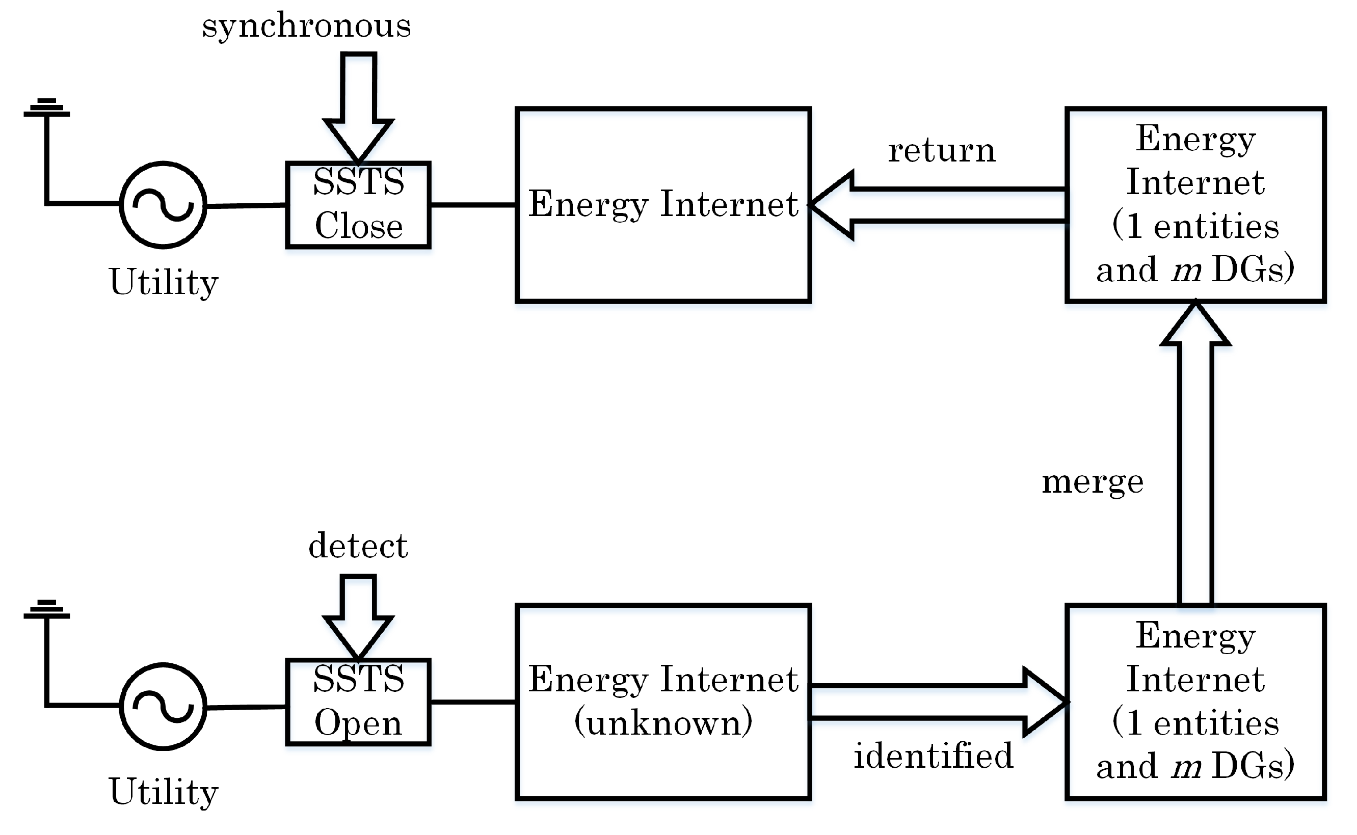
2] studied a suitable island management system by allowing active or passive islanding transition with intelligent control: island detection, identification, fragmentation to operate simultaneously, synchronous merging, and return-to-mains, as seen in
Figure 11. This well-equipped smart grid (by costly investigation) is a requisite to realizing this excellent performance.
Island Detection/Identification: The fault should be detected immediately, i.e., within 2 s according to the IEEE 1547 standard, to facilitate islanded operation to allow, for example, sufficient time to acquire data from the power system to make a decision before returning to DGs. The system management, therefore, should understand completely all components which identify the DGs in each intentionally islanded entity and then initiate an appropriate coordinated control strategy, resulting in load sharing within these island entities.
Island Fragmentation and DG Isolation: In order to ensure power supply continuity, some smaller island entities could be established after the fault. Since there are different configurations for each DG type, islanding protection may isolate the DG from entities, and the unbalanced power in such a case can cause frequency and phase deviations. The other DGs which stay connected should perform full frequency and phase control to compensate for power losses and any load disturbances.
Return-to-Utility and Island Merging: The smaller islanding entities might be merged to become a bigger one, and then the whole islanded area could reconnect to the utility. To identify the suitable moment to take this action, the energy management system should monitor all the circuit breakers inside the entities and the SSTS status based on the phase angles of the voltages of individual DGs. This task is important to recover the normal operation of the power system, although the islanded operation can last for a long time.
Normally, strategies for identifying and splitting the network into stable and maintainable islanded entities largely rely on prior knowledge of the system’s status, such as the matched load and generation in each entity, whether coherency is tight or slow among DGs, and the level of intelligence and flexibility of the MGs. In such a black start operation, frequency and voltage stability, active and reactive power flow control, active power filter capabilities, and storage energy management are the functionalities expected for eligible islanded entities [
12].
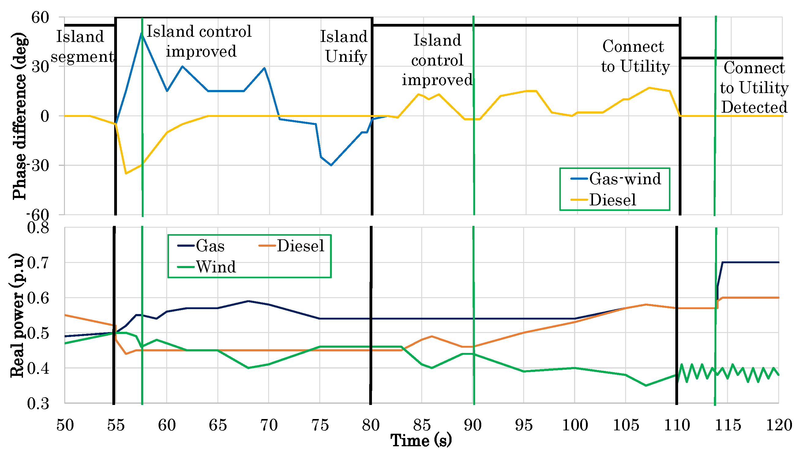
Because of the high penetration of RE with intermittent fundamental input energy and variable power outputs, consideration must be given to the ability of controllers to maintain frequency and voltage within limits; this is especially important for frequency variation, which is particularly restricted in the synchronous islanded operation mode. In
Figure 12, after the island fragmentation transient, the ’gas-wind’ island can be held within. When island merging occurs with the faster-responding diesel engine, control is improved and phase can be moderated. Therefore, faster-responding DG is beneficial. Additional phase control support for the island could be provided by other types of renewable technology, such as doubly fed induction generators (DFIGs) for the fast response of storage in the converter, energy storage with high-performance batteries, or a flywheel which can quickly balance a load–generation mismatch, and a load management system.
3.1. Improved Functions to Flexible Grids
In order to adapt to high-penetration RE power system, the following improvements to the conventional MG are fundamental:
Reliable islanding detection;
Accurate grid impedance estimation to facilitate droop control;
Improvement in the transient response of each component itself as well as the entire collaborative controller of MG;
Effective utilization of virtual impedance to share active/reactive power and harmonic components;
Improvement in adaptive droop control laws to increase the interactivity of the system;
Hierarchical controls applied smoothly to improve self-healing ability;
Enhanced voltage ride-through and power quality in the PCC regulated by DG units;
Consider black start operation of each islanded entity to facilitate synchronous multi-islanded operation;
More high-performance energy management support of ESSs.
These features will impart MGs with more intelligence and flexibility to integrate RE resources into the future smart grid.
3.2. Communication System
The modern communication network is more critical to the power system operation. It is expected to be secure, robust, scalable, and reliable, making it resilient to failures. The reconfigured grid has a two-way flow, not only of electricity but also information, leading to an automated power network. The messages exchanged through the communication networks consist of either information about the status of the grid or commands that enable status changes in the configuration of the network. Information and communication technology (ICT), Internet of Things (IoT), and Artificial Intelligence (AI) will thus play a major role in realizing modern power grids [
17]. The communication mechanism can use power line signaling, smart meter technologies, or other commercial infrastructures (e.g., satellite, telephone, wireless, power line carrier, fiber optics, or microwaves based on LAN or WAN) [
19]. Sensors need to be deployed in large numbers among MGs in order to efficiently monitor MG conditions, such as faults at the transformers, the status of the breakers, power flow magnitude, and flow directions in distribution lines.
In the multi-islanded operation, all entities are connected physically by interconnecting tie links and communicatively based on the high-bandwidth communication link. New communication protocols provide new functionalities, such as data routing, broadcasting, multicasting, and so on. In the paper by [
14], reliability communication is stated to have several facets: (i) probability that a given message will be lost entirely; (ii) use of redundant communication paths; (iii) automatic failure to protect against message loss; (iv) the expected time delay in delivering a message and the expected variability of that time delay; and (v) how competing messages may (or may not) be given priority when communication channels are saturated, known as quality of service.
When all information of the power system is stored online by IoT, protecting personal information related to utility customers and information about the utility itself is important. Since customer-level information is typically not very time-critical, slower and more computationally intensive mechanisms can typically be used to secure this information. A relatively critical protection requirement is placed on confidential information and the commands used to monitor and control the power system. To implement the best security, all the details of the security system should be published and well known, but the keys should be kept secret, where only the owner or another authorized party has the key. Applying a layered protection approach, with multiple levels of firewalls and “demilitarized zones”, requires more secure corporative firewall data.
4. Hierarchical Control and Seamless Mode Transfer
4.1. Seamless Mode Transfer
As mentioned previously, the hierarchical control which has long been applied to the AC power system can now be applied to energy management systems effectively operating in PEI-based MGs to facilitate seamless transfer between the grid-connected mode and islanded mode [
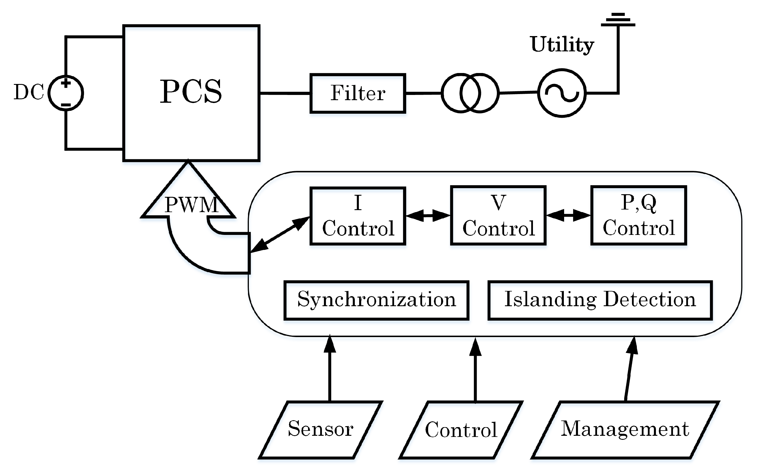
1]. The hierarchical control structure of a current-controlled DG interface employs a power-sharing control loop, voltage control loop, and current control loop, as shown in
Figure 13 [
22]. In the grid-connected mode, the reference voltage vector is generated to control the DG interface as a PQ bus or a PV bus. In the islanding transition and isolated modes, the autonomous power-sharing controller generates a reference current vector. In each mode, a robust voltage controller with internal model dynamics against random, harmonic, and unbalanced voltage disturbances is designed to reject a wide range of voltage disturbances associated with these modes (e.g., harmonic, unbalanced, and random voltage disturbances). These controllers can be designed to either adapt to any mode based on sensors or are switched when detecting a transfer between modes.
In grid-connected mode, the MG operates according to a standard, such as IEEE 1547-2003, UL 1541, or P1547.4.
The transition to the islanded mode occurs intentionally (e.g., maintenance) or unintentionally (e.g., faults). This mode is facilitated by fault monitoring, predictive maintenance, and protection.
In the islanded mode, entities must supply the required active and reactive powers, as well as provide frequency stability and operate within the specified voltage ranges.
Reconnection of the islanded entities to the utility will proceed as soon as the synchronization operation is made (matching the voltage, frequency, and phase angle between islanded entities and utility).
During the transient-to-islanded mode, the switching effect will impose voltage disturbances and a power angle on the output voltage of DG units, leading to the instability of power-sharing dynamics. This happens in conventional power controllers due to their lack of transient damping to react to large swings and is a large-signal stability problem. For a smooth transition, a possible countermeasure is adaptive transient droop control, which simultaneously facilitates a stable and reliable DG operation in both the grid-connected mode and autonomous operation.
Two categories can be distinguished to achieve seamless transitions. (i) The first category employs primary control loops implemented in the inverters, which make use of complex inverter topologies or control algorithms to complete the transitions. (ii) The second category uses a hierarchical architecture, as explained for MGs.
A study by [
36] combined a single-phase MG composed of voltage-controlled voltage source inverters (VC-VSIs) (for batteries and other energy storage technologies) and current-controlled voltage source inverters (CC-VSIs) (for renewable energy sources, such as PVs and micro wind turbines, to maximize power output), which worked together in both operation modes. The primary control structures for VC-VSIs and CC-VSIs were considered together with secondary control loops, which are used to synchronize the MG, as a single unit to the utility, rather than considering each unit separately. The integration of CC-VSIs into the MGs enables fault ride-through capabilities for these inverters which can continue to generate power for the MG, even during islanded operation; this MG can then seamlessly disconnect from the grid and operate autonomously, forming an island entity.
If the energy sources are RE, one of the VC-VSIs should also ideally include an ESS due to the intermittency of the power input. In such cases, an additional loop integrated into the primary control loops of the inverters monitors the state of charge for the ESS, MPPT for the PV and micro-WTs, etc. The primary control implemented in the VC-VSIs enables operation in the islanded mode or grid-connected mode through the use of the droop control technique and islanding detection algorithms. Secondary control loops optimizing MG operation are used to minimize the reactive power flows between these inverters and achieve reactive power sharing between the inverters in the islanded mode while also providing voltage and frequency restoration. The tertiary control layer considers the interaction between multiple MGs universally and the regulation of power flows across these MGs.
After faults, the aim is to transition from the islanded mode to the grid-connected mode, which requires a synchronous operation.
Because of the appearance of different DGs and ESSs with power electronic components, the synchronization operation of an islanded entity is a rapid dynamic response with small inertia and low overload capability [
37]. It is different from the quasi-synchronism control in power systems based on a regular rotating machine. In most existing work, MGs and utilities under ideal conditions (balance and no harmonics) are always considered when applying synchronization techniques and seamless reconnection to the utility. The controllers thus relate only to the synchronization control topology of basic positive series components. To achieve this control (control action), some methods enforce voltage at the link-feeder to directly track the utility voltage, which is rarely realizable due to the geographical location of DGs because they need to send a rapid communications signal in the time-domain, such as phase angles. Alternatively, a unified controller, which includes amplitude and phase compensators that control the local controllers of DG units, can be used. Thus, the droop curves can shift up/down at the same time in order to synchronize the islanded entities’ voltage with the utility.
Due to the low short-circuit ratio and limited capacity, in the islanded mode, PEI-based entities with no support from the stiff utility are sensitive to the problems of voltage, frequency, and harmonic. In conventional power systems, the voltage distortion (e.g., total harmonic distortion (THD) < 5% and unbalance factor (UF) < 2%) [
38] is hard to emphasize in the synchronization process enough to make the reconnection process destabilized. Therefore, under non-ideal voltages, this process should also account for the synchronization of negative-sequence and low-order harmonic ingredients. The secondary control level of the hierarchical control composition of islanded entities executes algorithms of both positive and negative components. As discussed above, to operate VSCs, two types of control strategies can be used. With CCVSC units, CC-VSCs will be synchronized with the utility by the local PLL. Therefore, the transition from islanded to grid-connected modes is not a significant issue. Besides, in islanded mode, DGs usually use VCVSC units to support voltage and supply power balance.
A distributed active synchronization algorithm can be applied for a smooth reconnection despite non-ideal voltages. All the DGs, ESSs, and loads decide the frequency and voltage of the islanded entities. Hence, synchronization control by using the secondary control level in the hierarchical control of controllable DGs is necessary to guarantee the stabilization of voltage/frequency and harmonics suppression of both islanded entities and the utility in the allowable range, according to any standard, before closing the SSTS. For example, for the voltage harmonics limitation in IEEE Standard 519-2014, individual harmonic distortion (IHD) < 3%, THD < 5%, and UF < 2%. Different harmonic components should be considered according to the specific application. For instance, all odd harmonic ingredients (1–13) should be considered in general cases (linear/nonlinear balanced/unbalanced loads). To achieve a smooth reconnection, the minimization of basic and harmonic voltage differences between islanded entities and the utility is a potential and effective solution.
4.2. Hierarchical Coordination of AC and DC MGs
Due to increasing of DC sources in terms of renewable energy, DC ESSs, super-capacitor modules, or hydrolysers and DC loads by means of PEIs among AC power systems, interest is rapidly growing in hybrid AC/DC MGs that combine both AC and DC systems coordinately to control the power flow between DC and AC parts. In this MG, the bidirectional interlinking converter that interfaces the DC subgrid to the AC subgrid plays a critical role. This converter links neighbor entities to form multi-MGs for power, supporting or enhancing the economic performance of the whole grid. Each cluster can manage their own frequency and voltage as an autonomous entity [
39]. The overall control of a DC MG needs more research attention [
1]. Studies on the topologies, architectures, planning, and configurations of MGs integrating different technologies—power electronics, telecommunications, generation, and ESSs—are necessary for ensuring a smooth transition between grid-connected and islanded modes. Compared with hierarchical control for large power systems with high inertia and inductive networks, in PEI-based MGs, there is no inertia, and the nature of the networks is mainly resistive. Contrary to that previously mentioned, in the control of a DC MG, a zero-layer of a zero-to-three level hierarchical controller has been adopted and organized, according to the literature, as follows.
Level 0 (inner control loops): current and voltage, feedback and feed-forward, and linear and nonlinear control loops of each module can be performed to regulate the output voltage and to control the current while keeping the system stable.
Level 1 (primary control): the droop control method is used to emulate physical behaviors that make the system stable and more damped. A resistive virtual output impedance loop is included that integrates the soft-start approach.
Level 2 (secondary control): maintains the normal values of frequency and voltage amplitude inside the DC entity by the virtual inertia and output virtual impedance, which is related to the other control loops, such as inner current, voltage loops, and the droop control, in order to run a synchronization operation for seamlessly reconnecting to the utility.
Level 3 (tertiary control): controls the power flow among DC or AC entities and utilities.
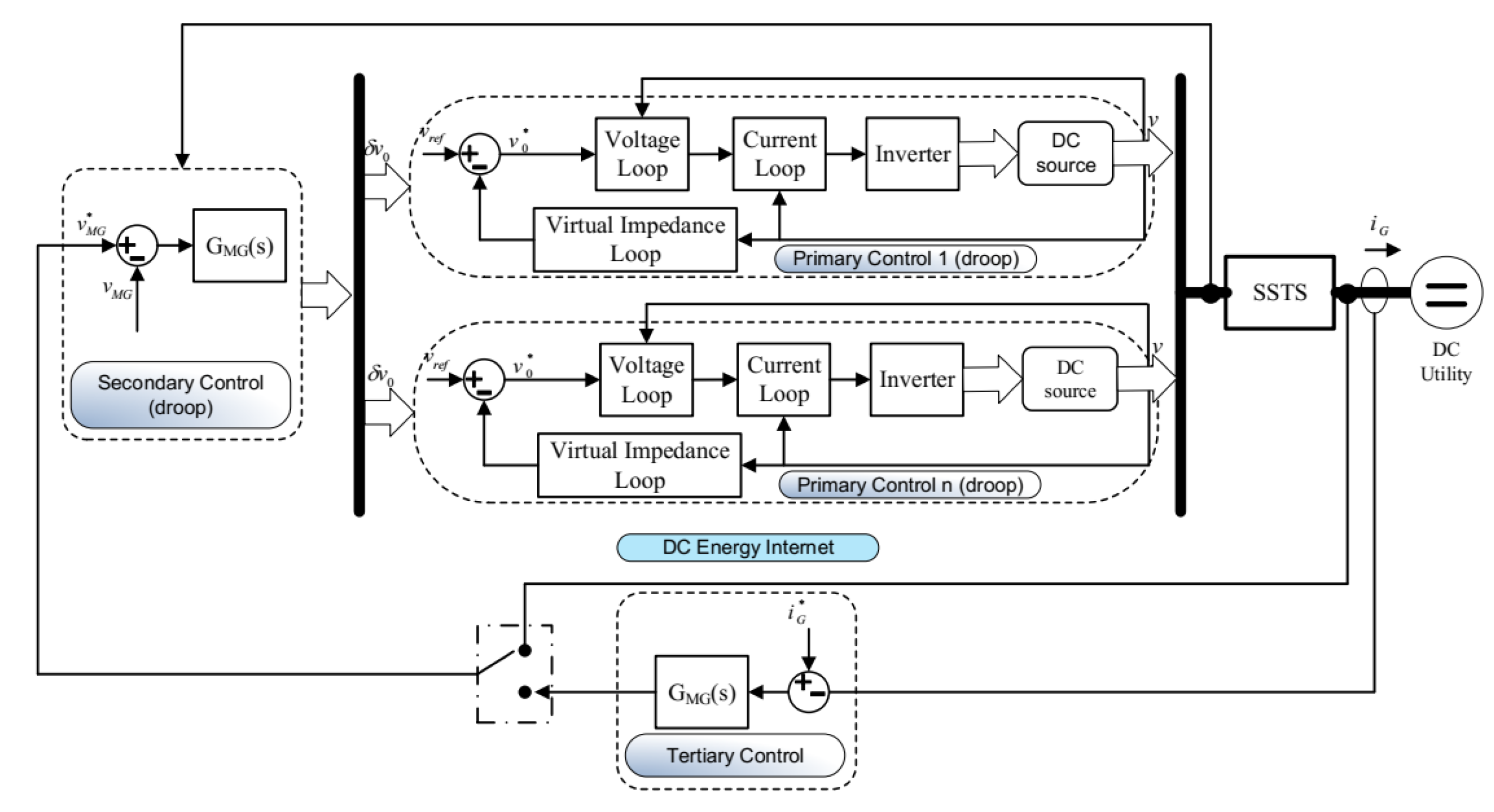
Figure 14 shows the primary, secondary, and tertiary controls of a DC MG. Once the DC MG is connected to the DC source, the power flow can be controlled by changing the voltage inside the DC MG. By measuring the current iG (or the power) through the SSTS, it can be compared with the desired positive or negative current
(or power), depending on whether energy is imported or exported.
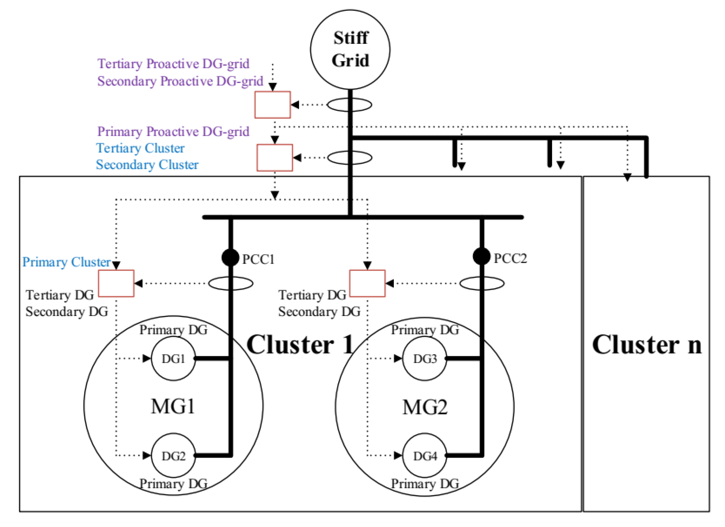
In
Figure 15 is a multi-MG cluster which, in a universal view, constitutes a proactive DG grid regardless of whether it is a DC or AC configuration. Each MG has its own hierarchical controller. Communication among MGs uses hierarchical controllers. The tertiary control of a cluster can provide high-level inertia to interconnect more MGs and fix the active and reactive power to be provided by this cluster, or it can act as the primary control to interconnect more clusters. The secondary control sends all references to each cluster of MGs to restore the frequency and amplitude. As a result, we can scale the control hierarchy as necessary. Using this approach, the system becomes more flexible and expandable, and, consequently, it can integrate increasingly more MGs, without changing the local hierarchical control system associated with each MG.
4.3. Synchronous Operation for Reconnection
After a fault is cleared, an islanded entity is normally required to change its operational mode to grid-connected by reconnecting to the utility after synchronizing its operation. Contrary to a single machine using a synchronizer (phase angle, slip frequency, and voltage difference), the synchronization of islanded entities operating with many active components (such as REs, ESSs, and conventional generators) needs to be controlled in a coordinated way. This complicated scheme utilizes various PEI-based DGs, as well as the collaboration of alternator-based generators, which determines the frequency and voltage of entities. The common synchronization method, which waits for the fulfillment of synchronizing criteria while maintaining the entity’s frequency and voltage at fixed values, does not always yield consistent results. For example, it takes a very long time until the phase difference matches the criteria. Also, an important factor in measuring the synchronizing criteria is the estimation of the phase and frequency during non-ideal conditions. During synchronous operation, since the entity operates as an independent system, fast and robust voltage and frequency control must be provided even under harmonics, unbalanced loads, and noise [
40]. Recently, most control strategies have been droop-based methods and/or master/slave control methods. DG units can be classified in power-controlled and voltage-controlled units. In the islanded mode, to maintain the voltage and frequency within the acceptable limits, at least one of the DG units is required to operate by a voltage-controlled mechanism. In droop-based methods, all DG units are involved in regulating the voltage and frequency of islanded entities. In the master/slave method, a DG unit with the highest power rating is responsible for regulating the voltage and frequency, as the master unit and the other slave units produce pre-specified amounts of active and reactive power. Master/slave control schemes are found to be both costly and unreliable [
41].
In islanded entities, controllable energy sources consider the battery energy storage system (BESS) and diesel generators while REs, including PV, WTs, fuel cell, etc., are regarded as uncontrollable due to intermittent input energy. If an islanded entity has no rotational DG, the smart PCS of a PV or WT system will manage the frequency and voltage. The fuel cell generator, which needs a long time to change its output, is responsible for the lowest frequency band using a low-pass filter. The diesel generator takes charge of the middle-frequency band using a bandpass filter. The BESS, which has the fastest response, should control the higher frequency band. In another scheme, diesel generators with a larger capacity (50 kW) are used for the lowest band, and smaller diesel generators (20 kW) take charge of the middle-frequency bands.
To facilitate a synchronous operation, the SSTS connecting the utility and an islanded entity normally use an intelligent electronic device (IED). The IED compares the criteria parameters of two sides for synchronizing criteria and switching the SSTS. It senses and compares the magnitude, frequency, and phase of the voltage of both sides during parallel operation to determine the synchronizing criteria. Signals can be measured by using a reference frame (fixed or rotating) transformation-based method under balanced or even unbalanced conditions [
21]. In the islanded mode, the BESS acts as one of several controllers for frequency and voltage control. Unlike the grid-connected mode, the BESS does not strictly follow the reference values but uses the droop strategy [
20]. A number of feedback signals, such as the voltage, current, frequency, and power, must be measured or calculated to support the BESS controller. During autonomous operation, many inverter-based DGs adopt the droop strategy for stable power-sharing. Determining precisely the components of unintentional entities in this mode is important for a central controller. That controller is used for active synchronizing control through the communication network. At first, it decides on the system’s operational mode according to the SSTS connection status sensed by the IED. Then, it sends the operational command to every controllable DG to control the frequency and voltage of the synchronized entity. In this mode, the REs operate with MPP tracking to maximize the generation efficiency. Not only is it uncontrollable, but it also acts as a disturbance in the maintenance of the stable voltage and frequency of the islanded entity.
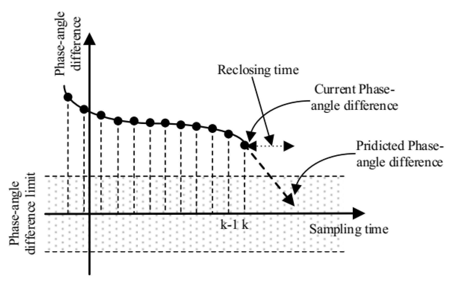
The primary objective of active synchronizing control is to minimize the difference between these signals to satisfy the synchronizing criteria by manipulating output set-points of controllable DGs (weighted with the weight factors). The reclosing decision is made within a predetermined limit, which is irrespective of the exact moment of zero-crossing difference, as seen in
Figure 16 Reclosing outside of the limit results in a big bump between two voltages.
5. Voltage and Frequency Quality during Islanded Operation
5.1. Enhancing Voltage/Frequency Quality in Various Modes Using ESS
In the grid-connected operation, all DGs and ESSs are in the PQ control mode, where the MMS provides the output active and reactive power set-point via the
d-and
q-axis current commands. MGs have been typically regarded as a resistive or inductive systems in previous studies [
1,
42,
43,
44,
45,
46,
47]. The different droop control strategies are applied depending on different system types. In islanded operation, the upper grid controller regulates the frequency and the voltage of the entity and also outputs the
d-and
q-axis current commands. During this mode, the power balance between supply and demand does not match, leading to voltage/frequency fluctuation. Then, the power balance is ensured by decreasing the generation or by load shedding to avoid a blackout. The frequency/voltage control of the islanded entity is not straightforward. For an entity which is composed only of RE units and conventional power units (the diesel generator, gas engine, and micro-turbine), it is hard to ensure good dynamic performance: due to a relatively slow response time and intermittent power outputs, it is not possible to guarantee the power demands. Meanwhile, conventional systems are limited by their insufficient dynamic performance for load tracking. In particular, the local frequency of the islanded entities may change rapidly due to the low inertia of the entire system. To overcome these limitations, the introduction of an ESS is considered an effective solution to ensure power balance since this device is based on a power electronic device and has a very fast response time (in ms). The storage system in the entity is analogous to the spinning reserve of large generators in the conventional grid. The intermediate ESS is an inverter-interfaced battery ESS bank (BESS), compressed air energy storage (CAES), superconducting magnetic energy storage (SMES), electrochemical capacitor energy storage (ECES), supercapacitor, or flywheel energy storage (FES) [
48].
A properly designed ESS can allow a system to stabilize by absorbing and injecting instantaneous power. In previous studies, some ESS models have been proposed [
49,
50,
51,
52,
53]. A cooperative control scheme between the ESS and other DGs is needed to effectively achieve the goal in islanded operation. A two-level control concept, which consists of primary and secondary control, has been proposed to stabilize the frequency of islanded entity: the primary control action in the ESS and the secondary control action in the entity management system (EMS). Fast-acting ESSs can effectively damp electromechanical oscillations because they provide storage capacity in addition to the kinetic energy of the generator rotors, which can share sudden changes in power requirements [
9]. Additionally, the EMS of the central controller of islanded entities deals with management functions, such as disconnection during faults, switching to other controllers of all components of the entity, resynchronization after fault clearance, and the load-shedding process. This central controller is also responsible for the supervisory control of DGs and the ESS units by universal communication. By using collected local information, the controller generates a power output set-point and provides it to the primary controller of each DG unit and ESS unit to ultimately control the power output according to the given values. Fundamentally, the control capability of the ESS for balancing between generation and consumption may be limited by its available capacity. Therefore, the power output of the ESS should be brought back to zero as soon as possible by the secondary control in order to secure the maximum spinning reserve.
The secondary control algorithm of the central controller compares the measured power output of ESS (
and
) and the reference value (
and
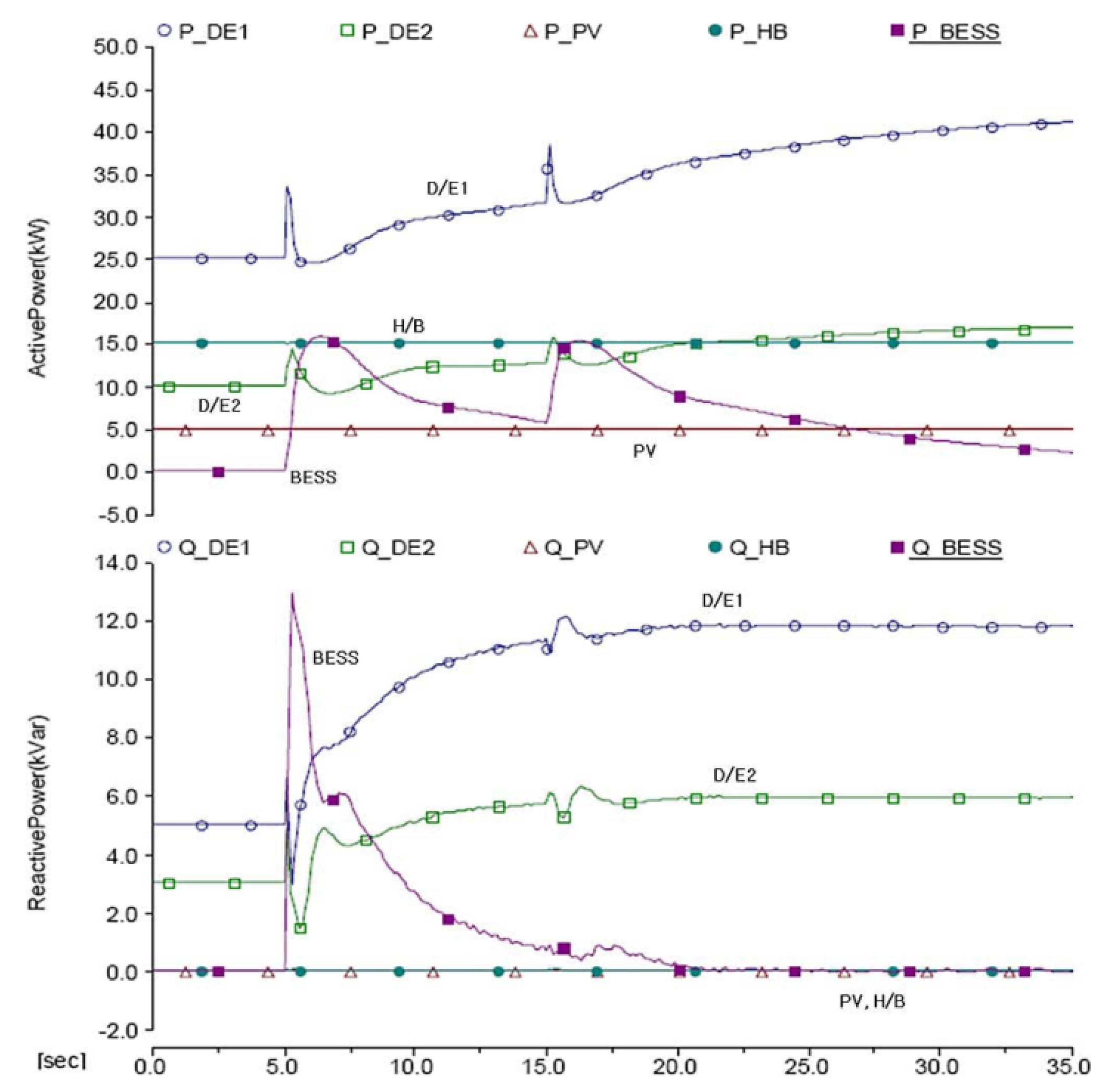
) to obtain the error. This error generates the total required power and sends the commands to dispatch power output set-points for each individual controllable DG unit based on its participant/weighted factor, which normally depends on its capacity. During islanded operation, the power output of diesel generators is also changed from an initial constant value to a new power set-point calculated by the secondary control, as shown in
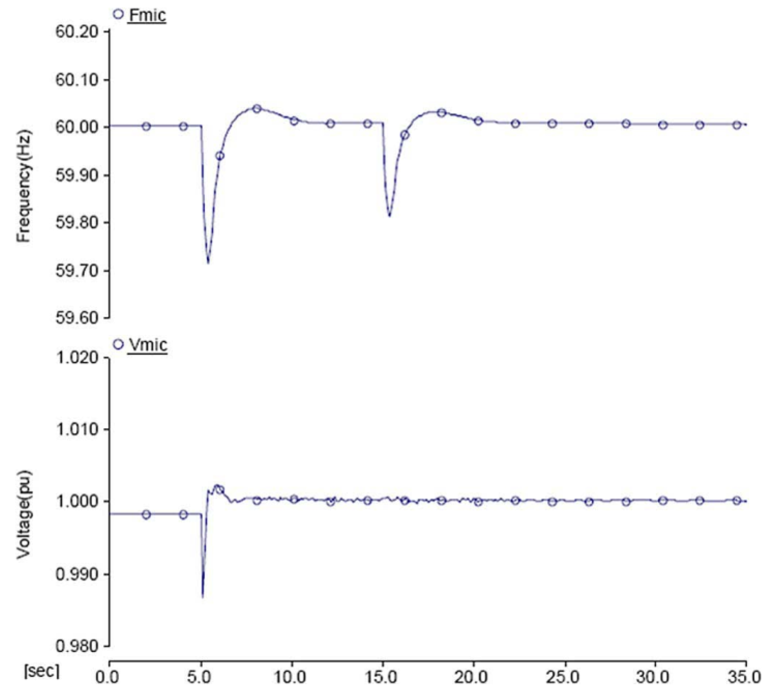
Figure 17 at t = 5 s. In this figure, the BESS is specifically tested to represent the ESS system. In the second event, 10 kW of active load change at t = 15 s, the ESS can afford to inject the necessary active power into the entity to ensure power balance because the power output of the ESS is bringing it back to zero; thus, it has sufficient spinning reserve margin. The power outputs of the diesel generators are changed from the initial constant values to new set points by the central controller. Facilitated by this cooperative control, the frequency and the voltage can be regulated at nominal values successfully, as shown in
Figure 18. Like a BESS, the PEI-DG can respond quickly enough to implement droop control during the islanded operation. PEI-DG, however, depends on primary resources and a BESS depends on the SOC. Therefore, both BESS and PEI-DG need to depend on slow-response DG units, such as a diesel or gas generator, for secondary control.
5.2. Load-Sharing Operation of Distributed MGs
Generally speaking, in an islanded entity, unbalanced and/or nonlinear loads such as motors might exist. Normally, the impedance load can absorb a sudden change in instantaneous real and reactive power, such as an infinite sink. However, with motor loads, a sudden change in the terminal voltage leads to a large oscillation in the real and reactive power level. Furthermore, the line impedances are not purely resistive or inductive, and the control of active and reactive power is not totally decoupled in nature. Therefore, in terms of total harmonic distortion and voltage imbalance indexes, the islanded entity should share the common loads entirely to ensure that quality within the islanding entity is maintained as it is in the grid-connected mode.
The conventional method for local load sharing is the droop characteristic using feedback local signals. The droop coefficients are chosen to meet the voltage requirements at PCC points and based on the rating of DGs. With non-ideal loads, both active and reactive power have double the frequency and distorted components over the average components. Thus, DG units should supply double the frequency and distorted components to compensate for the unbalance and harmonics. The central controller is informed clearly of the status of all loads, DG units, and other parts among islanded entities by using a reliable communication system [
10].
Calculating the output impedance of DG units, the feeder, and local loads can affect power-sharing, especially in
Q-V droop control. However, due to the complex structure of an islanded entity, the system impedance cannot be straightforwardly estimated. Communication-based solutions are utilized to improve the sharing accuracy. Although the diverged locations of DG units challenge this method now, it is expected to be solved soon by improved communication technology at low cost, such as wireless solutions. In another approaches, the whole MG system is proposed to be composed of a certain physical network and several DG units in order to have most islanded entities in a clear configuration. Each DG unit can be equivalent to a droop-controlled voltage source (DVS) in series with a DG feeder. The DG feeder can be either a coupling inductor or a virtual feeder if the virtual impedance method is applied. By separating DVS units from the system, the equivalent network of an MG is obtained. For example, the equivalent network in its entirety contains
s DG feeders,
n network feeders,
s DVS nodes and
m network nodes, where s is the number of DG units. Finally, the system impedance can be estimated in any islanding case [
54].
5.3. Voltage Quality
The droop control used to share loads during the islanded mode was conventionally designed for large synchronous generators in the balanced condition. Therefore, while applying it to a system with unbalanced loads, the unbalanced load currents flow through line and converter impedances, giving rise to unbalanced terminal voltages which can trip off sensitive loads. When the voltage unbalanced factor (VUF) thresholds of local buses are exceeded, to eliminate any tripping, one costly solution is to install additional equipment, such as active power filters (APFs), static synchronous compensators (STATCOMs), dynamic voltage restorers (DVRs), or unified power quality conditioners (UPQCs). A less costly but complicated alternative is to slightly enhance the capacity of existing converters of DG units and to modify their control algorithms to include some compensation functions. Through proper control, unbalanced voltage is mitigated by injecting negative-sequence currents through the current-controlled DG converters. Unbalanced voltage can also be compensated for by using multiple DGs.
In order to achieve negative-sequence reactive power sharing, each DG is controlled as a negative-sequence conductor with its conductance drooping, along with the negative-sequence reactive power flow. However, the negative-sequence current sharing performance is affected by line impedance and droop coefficient mismatches. In this case, a droop controller can insert negative- and zero-sequence tunable virtual impedances, in addition to the usual positive-sequence impedance, allowing the DGs to perform selective voltage compensation. Normally, the enabled DG units maintain VUFs of the buses of interest at their thresholds, which can help to limit the currents passing through the enabled DGs while protecting their local sensitive loads.
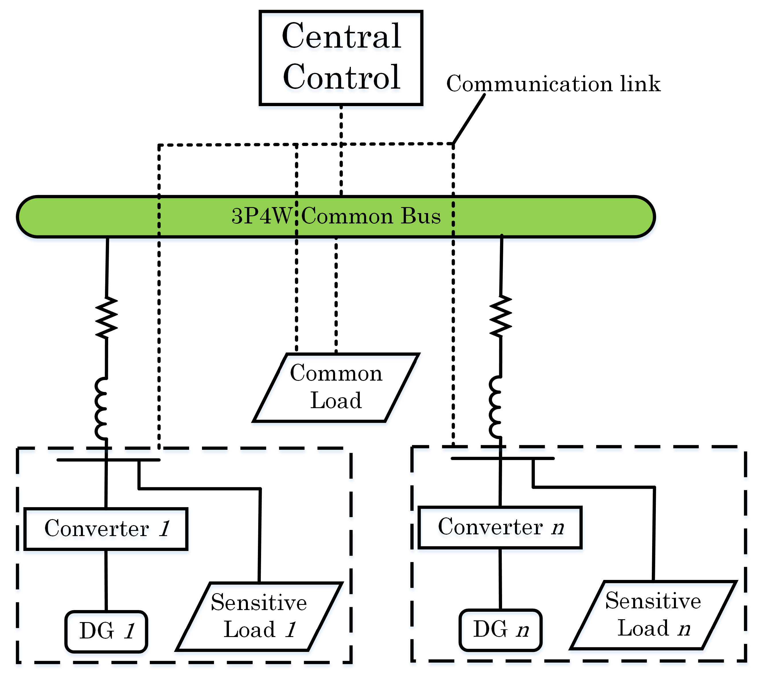
In the case of a three-phase four-wire system, where four-leg converters are used for supplying single- and three-phase loads with an additional zero-sequence current return path, sharing an unbalanced load current among those four-leg converters also needs to take the zero-sequence component into account. It is necessary that the critical loads are placed close to converters with the compensation ability whenever their VUF exceeds certain thresholds. A three-phase four-wire islanded entity with
n DG units is shown in
Figure 19. Each DG is tied to its local bus by a three-phase four-leg converter. The four-leg converters must regulate their respective bus voltages and share the loads by applying droop control. The positive-sequence current component and negative-, zero-sequence current components under unbalanced loads need to be addressed separately. All DGs are set to have the same p.u. power ratings and the control scheme is implemented in the
dq0 synchronous reference frame. The central controller facilitated by communication links measures the voltage of the common bus, makes the management decision, and then transmits the compensation references to the DG units [
26].
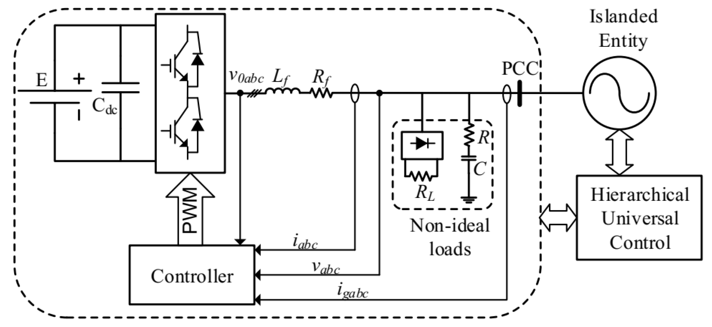
The configuration of a multi-functional inverter (MFI) with an ancillary service of voltage/frequency quality enhancement is depicted in
Figure 20. With this system, extra voltage/frequency quality conditioners may no longer be essential in an inverter-dominated entity, avoiding additional investment and operational cost. Since it is the auxiliary function of an MFI, its capacity for voltage/frequency quality enhancement is limited and related to its working condition. Optimally utilizing the limited capacity of an MFI for harmonic and reactive power issues should be assigned with independent weights to enhance the voltage/frequency quality of the islanded entity as much as possible [
55].
To integrate multiple MFIs into one power entity, a universal controller (UC) needs to be deployed. This controller utilizes a multi-objective optimal compensation model to assign the optimal compensation coefficients to each MFI based on the given initial information of the optimal model. In general, this control might use a hierarchical mechanism, and the optimal compensation may be embedded in the tertiary control to provide optimal voltage/frequency quality services. With the guide of the UC, each MFI partly compensates for these issues in the MG according to the multi-objective optimal model in the tertiary control. Each MFI can autonomously work as an individual module without needing information from the other ones. In secondary control, the power output of MFIs is exchanged and modified by the UC to ensure the safe and economic operation of the islanded entity. In the local primary controller of the MFI, an output current-tracking controller is embedded so that the MFI generates the desired active, reactive, and harmonic current that fulfill the functions required by the DERs interfacing with the utility and enhances the quality of voltage/frequency of the entity.
6. Conclusions
This paper discusses the islanding phenomenon and the subsequent required actions to maintain power supply with high penetration of RE. The self-control of a DG unit and central control using a hierarchical scheme are explained in detail. The ability to operate in the conventional grid-connected mode or islanded mode and the smooth transition between the two based on an advanced controller are highlighted.
Many objects are discussed in this paper, including multi-agent systems for the Energy Internet, flexible operation in the “flexible islanded operation of proactive DG grids”, hierarchical control of islanded entities, droop control (both conventional and advanced) for load sharing without communication, the intelligent controlled islanding scheme, and the role of the ESS in islanded entities, all of which show the flexible operation of the future power system.
Future perspectives of the power system with high DG penetration are also presented on the basis of discussions about improved functions for flexible grids and communication systems.
Moreover, knowledge surrounding hierarchical control and seamless mode transfer, such as seamless mode transfer, hierarchical coordination of AC and DC MGs, and synchronous operation for reconnection, is also considered to be an important part of this paper.
Furthermore, discussions regarding power quality (voltage, frequency, and harmonic) during islanded operation are given to cover some important aspects of power generation.
Finally, for the smart and resilient operation of the emerging power system, many research directions which need investigation are presented, such as robust hierarchical controllers, advanced droop control, active/reactive power sharing, harmonic mitigation within an islanded entity, high-performance ESS and its controller, and reliable communication systems.


