An Improved Stopband Dual-Band Filter Using Quad-Mode Stub-Loaded Resonators


1
School of Information Engineering, Putian University, Putian 351100, China
2
Department of Electrical Engineering, National University of Tainan, Tainan 700, Taiwan
3
Graduate Institute of Materials Engineering, National Pingtung University of Science and Technology, Pingtung County 912, Taiwan
*
Author to whom correspondence should be addressed.
Electronics 2021, 10(2), 142; https://0-doi-org.brum.beds.ac.uk/10.3390/electronics10020142
Submission received: 29 November 2020
/
Revised: 6 January 2021
/
Accepted: 7 January 2021
/
Published: 11 January 2021
(This article belongs to the Special Issue Microwave Devices Design and Application)
Abstract
:In this paper, we present a dual-band microstrip bandpass filter (BPF) with an improved stopband, which was constructed by a quad-mode stub-loaded resonator (SLR). Since the SLR is able to produce multiresonance within a single unit, the area saving is significant. The proposed quad-mode SLR was implemented by two stubs allocated at symmetry places, thus the even-/odd-mode can be applied to analysis the resonance. Moreover, to shift the spurious passband, the step impedance structure was applied to shift the harmonic resonance to the higher frequency. Design procedure for high performance dual-band BPF is proposed, and filter examples were designed for wireless local area network (WLAN) of 2.4/5.2 GHz. The measured insertion losses, return losses and fractional bandwidths (FBW) are 1.43 dB, 10 dB, and 14.8% at 2.4 GHz and 1.34 dB, 10 dB, and 12.9% at 5.2 GHz. Moreover, by applying two quarter-wavelength stubs on the input/output ports, the passband selectivity with an isolation of 40 dB can be achieved. The simulation and measurement have a close match, verifying the design concept.
1. Introduction
The multiband and high selectivity microstrip bandpass filters (BPFs) are highly required due to the increasingly demand of the wireless communication. Multimode resonator (MMR) is one of the vital methods to carry out wider or numerous bands [1] since it provides multiresonant modes within a single unit, which can be considered area saving as well. Several forms of MMRs, especially step impedance resonator (SIR) [2] and stub-loaded resonator (SLR) [3], have been proposed to form multibands or a wider passbands.
Figure 1 shows some forms of multimode resonators, such as (a) SIR-type 1, (b) SIR-type 2, (c) SLR, and (d) stub-loaded stepped impedance resonator (SLSIR). The SIRs with type 1 and type 2, as shown in Figure 1a,b, are known to shift the spurious response to higher or lower frequency, respectively [2]. Several modified SIR have been proposed, such as trisection SIR, asymmetry SIR, and quarter wavelength SIR, to form multiband or wideband performances [4,5,6]. SLR is also a convenient method to produce additional resonances, which is beneficial for constructing multibands or receiving wider bandwidth filters. The conventional scheme of SLR as shown in Figure 1c is based on a λ/2 line with a λ/4 stub attached to split modes and generate a transmission zero. The SLR can be further interpreted as two λ/4 lines; moreover, the even- and odd-mode analysis can be applied simply to explain the resonance. Similarly, several modified SLR have been proposed, such as open-circuited/short-circuited stubs, dual stubs, and step-impedance stubs, to form multiband or wideband performances [7,8,9,10,11,12,13,14,15,16,17]. In 2011, Zhu et al. proposed a class of triple-/quad-mode stub-loaded resonators [8]. A pair of identical open-ended stubs, shorter than λ/2, were tap-connected to a λ/2 resonator at symmetrical positions with respect to their center. It caused three adjacent resonant modes, while producing a transmission zero at higher frequency. Moreover, a single open-ended stub, longer than λ/2, was introduced at the center of the resonator. This arrangement was made to bring out a fourth resonant mode approaching the above three modes while causing a transmission zero below all of them. In 2013, Sun et al. proposed a quad-mode SLR [9]. Each of the quad-mode equivalent circuits was a quarter-wavelength resonator. The stub-to-stub coupling was introduced to split two identical odd-modes. Meanwhile, these two coupling stubs were folded inward, and a new transmission zero was produced, which separated quad-mode into two parts corresponding to two passbands: the first one was formed by even-modes and the second one was composed by odd-modes. In 2019, Weng et al. proposed compact ultra-wideband bandpass filters achieved by using a stub-loaded stepped impedance resonator (SLSIR), as shown in Figure 1d [16]. The even and odd input impedances of the stub-loaded stepped impedance resonator were derived to discuss the resonant modes of the resonator. However, SLR might also suffer from the spurious band, which is generated either by the extra resonant path or the passband at central frequency. Step impedance structure is a functional solution for the band tuning, which allows the designer to adjust the passband by choosing various length or impedance ratios [17].
In this paper, a high performance dual-band BPF was carried out by a quad-mode SLR, formed by a microstrip line resonator with two pairs of stubs and a shorted-circuit stub. The first pair of stubs were designed for the first passband, while the other pair of stubs were for the second passband. However, combination of two different stubs causes the undemanding resonant path, which produces the spurious band. The proposed rejection band is improved by applying step impedance structure to shift the spurious resonance to a higher frequency. This study provides another design procedure for the dual-band BPF using the quad-mode SLR with step impedance structure without using the conventional method of deriving the input impedance/admittance for analyzing the even/odd mode resonant mode. The proposed method can quickly achieve the dual-band response by using two pairs of the uniform impedance structure to simplify the design complex, and then shifting the spurious resonance by introducing the step impedance structure without degrading the passband response as carefully meeting the required resonant conditions. The proposed method has the advantage of an intuitive and easy design. The filter examples were designed, fabricated, and measured. The simulation had a close match with the measurement, verifying the design concept.
2. Design Procedure
Figure 2 shows the layout of the proposed quad-mode SLR. The main structure is the microstrip line resonator with two pairs of stubs (stub 1, stub 2 and stub 3, stub 4) and a shorted-circuit stub at the symmetry point. The microstrip resonator with stub 1 and stub 2 is used to form the first passband while the microstrip resonator with stub 3 and stub 4 is used to form the second passband. In this study, the used substrate parameter for the filter design and fabrication was Roger Duroid RT 5880 (manufacturer is Rogers Corporation, and the substrate is sourced from Rogers Taiwan, Inc. of, New Taipei City, Taiwan) with a thickness of 0.787 mm, a dielectric constant of 2.2, and a loss factor of 0.0009. The simulation tool was IE3D of Zeland Software Inc., Fremont, CA, USA [18]. The design procedure for the dual-band filter using proposed quad-mode SLR is described in the following section.
2.1. Prototype Design of Dual-Band Filter
In the first step, a prototype of dual-band filter using the proposed quad-mode SLR is shown. However, for the prototype design, the proposed quad-mode SLR was initially formed by using uniform impedance structure instead of step impedance structure, thus reducing the design complex [8]. Since the circuit is symmetrical, the equivalent circuit can be modeled as the even-mode and odd-mode [18]. Figure 3 shows (a) the equivalent circuit of the proposed quad-mode SLR using uniform impedance structure, (b) even-mode, and (c) odd-mode. It was clearly found that the equivalent circuit of the proposed quad-mode SLR with even-mode and odd-mode is the length of LS. When the even-mode and odd-mode occurs, the symmetric plane behaves as a magnetic wall and an electric wall, and then the shorted-stub (LS) is created and ignored, respectively [19]. Figure 4 shows the lengths of the quad-mode in the proposed SLR, including mode 1 and mode 3 of even-mode, and mode 2 and mode 4 of odd-mode. As shown, the length of LS under the even-mode can be used for the splitting of even-mode from odd-mode.
In this filter prototype, a dual-band filter using quad-mode SLR with uniform impedance structure was designed for wireless local area network (WLAN) of 2.4/5.2 GHz. Figure 5 shows four resonant modes as the resonant paths for the passband 1 (PB1) of 2.4 GHz and passband 2 (PB2) of 5.2 GHz. That is, the resonant path between stub 1 and stub 2 are resonant and responsible for PB1, and the resonant path between stub 3 and 4 is resonant and responsible for PB2.
Figure 6 shows effect of LS on the splitting of even-/odd-mode. Since the length of LS at the symmetric plane controls the splitting of even-/odd-mode, the passband 1 (PB1) is formed by coupling mode 1 (even-mode) and mode 2 (odd-mode) and the passband 2 (PB2) is formed by coupling mode 3 (even-mode) and mode 4 (odd-mode) after reaching the desired LS. When LS = 0.8 mm and LS = 1.6 mm, mode 1 and mode 3 are split to mode 2 and mode 4, respectively. When LS = 1.2 mm, mode 1 and mode 3 can be coupled to mode 2 and mode 4 to have desired return losses both at 2.4 GHz and 5.2 GHz.
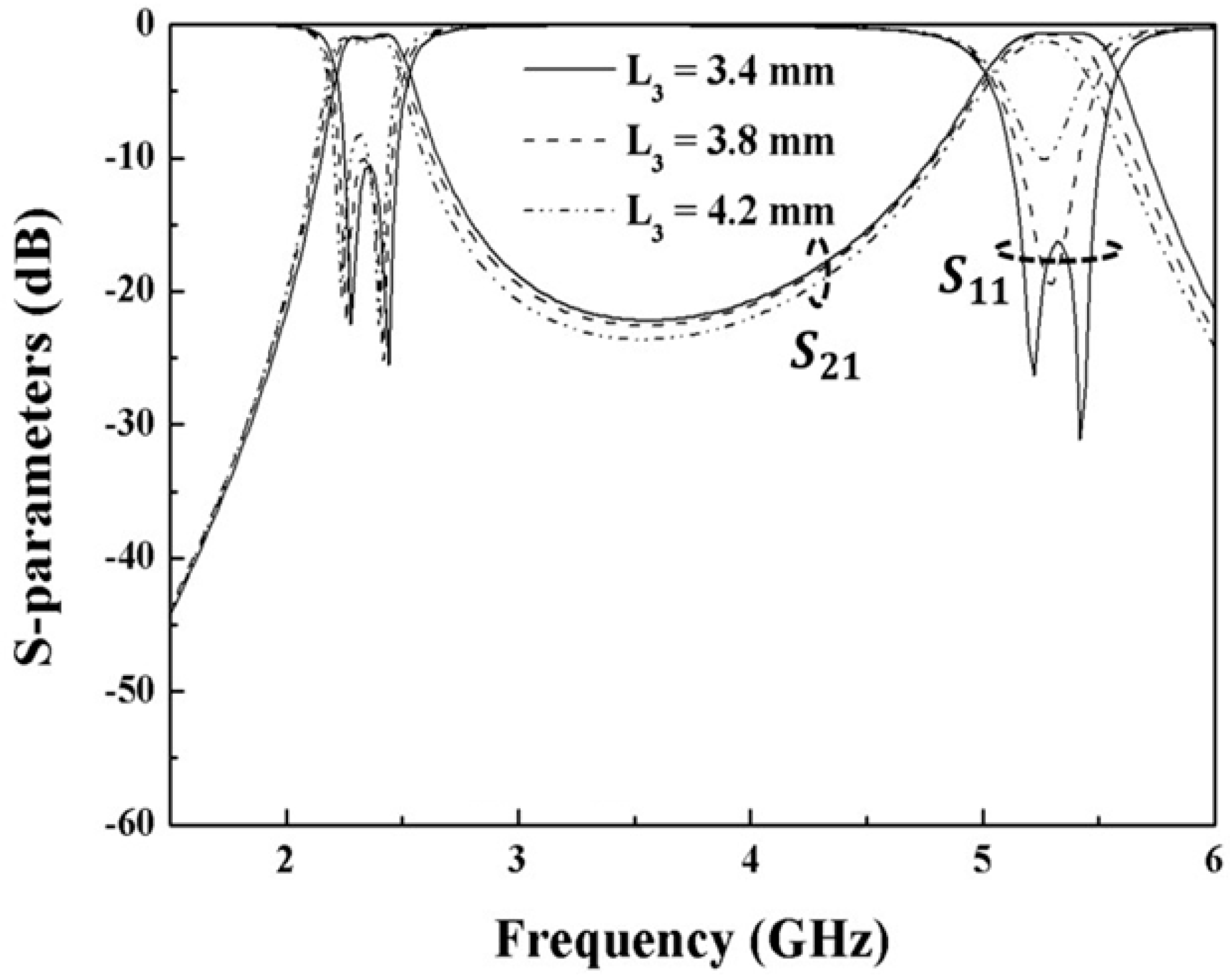
Figure 7 shows effect of L3 on the filter responses of the PB1 and PB2 as L1 = 14.2 mm, L2 = 5.3 mm and LS = 1.2 mm are kept. As shown in Figure 4, L3 could affect PB1 and PB2 simultaneously. When L3 is 3.4 mm, the PB1 and PB2 can have desired filter responses with low insertion losses less than 2 dB and high return losses larger than 10 dB both at 2.4 GHz and 5.2 GHz, respectively.
Therefore, the proposed filter using SLR with uniform impedance structure is obtained with the parameters: L1 = 14.2 mm, L2 = 5.3 mm, L3 = 4.2 mm, LS = 1.2 mm. However, the extra path (with length of L1 + L2) constructed by stub 1 and 3 forms the spurious resonance at 10 GHz (as shown in Figure 8).
2.2. Shift of the Spurious Response
In the second step, a dual-band filter using quad-mode SLR with step impedance structure is presented. As discussed in Section 2.1, the dual-band filter using quad-mode SLR with uniform impedance structure has a spurious response at 10 GHz due to the extra resonant path. It is known that spurious resonance can be shifted to a higher frequency by introducing the step impedance structure to replace the uniform impedance structure [2], as shown in Figure 2.
As discussed in previous section, the PB1, PB2, and spurious response are resonant at different paths. Thus the step impedance resonator (SIR) can be useful for these three resonant paths. Figure 8 shows the equivalent circuit of the proposed quad-mode SLR using step impedance structure. The impedance ratio (K) is given as K = Z2/Z1 and electric length ratio (α) ratio is given as α = θ2/(θ1c + θ2) = θ2/θtc. The resonant condition is further determined from input admittance Yin = 0 [20], and the following conditions are also satisfied:
Plenty of solutions for θtc can be satisfied for various combinations of α and K. In this study, K was set as 0.535, and the proper L3 and LS (of Figure 2 in Section 2.1) were selected by the previous section, which were not expected to be varied. The main design concept is that careful selection of the electric length ratio (α) keeps the PB1 and PB2 unchanged and removes the spurious response to higher frequency. The step impedance structure with the correlated parameters of electronic length ratio α and impedance ratio K allow the proposed design to obtain the adjustment of spurious resonance easily. The maximal frequency shift rate can be achieved by properly choosing α value and K value of the step impedance structure. It is expected that if K is set much less than 1 or much larger than 1, the maximal frequency shift rate can be larger by properly choosing a α value with a specific K value. In this work, θ2, along the resonant path constructed by stub 1 and stub 3, was obtained as 44° at 5.2 GHz and 20° at 2.4 GHz to meet the target of spurious band shift. Figure 9 shows the comparison of the dual-band filter using the proposed quad-mode SLR with uniform impedance structure and with step impedance structure. The result shows that the spurious band shifted from 10 GHz to a higher frequency of 11.8 GHz without degrading the dual passband performances.
Unlike the conventional method of deriving the input admittance for analyzing the even-/odd-mode resonant mode, the proposed method uses another design procedure for the dual-band BPF using the quad-mode SLR with step impedance structure. The resonance of the step impedance structure has been discovered by many works, through which the correlated parameters of electronic length ratio α and impedance ratio K allow us to obtain the adjustment of spurious resonance easily. Figure 10 summarizes the design procedure of the dual-band filter using the proposed quad-mode SLR with step impedance structure. The steps are simply summarized:
1. Predesign the prototype of dual-band filter using quad-mode SLR with uniform impedance structure as shown in Figure 3;
2. Introduce the step impedance structure to replace the uniform impedance structure and then design the length ratio and impedance ratio by fixing the L3 and LS (of Figure 3);
3. Select the length ratio and impedance ratio of the step impedance structure to shift the spurious response;
4. Check the length ratio and impedance ratio of the step impedance structure to match the passband responses of the PB1 and PB2.
2.3. Improvement of the Selectivity
In this section, the selectivity of the dual-band filter using quad-mode SLR with step impedance structure is improved. Figure 11 shows dual-band bandpass filter with improved selectivity by adding two open stubs (L4) on the input/output (I/O) ports. The length of the open stub (L4) is set as the quarter-wavelength bandstop structure at 3.8 GHz to provide the isolation between the two passbands by providing the transmission zeroes between two passbands [14]. Moreover, the two open stubs (L4) are also set close to have the effect of the source to load coupling to provide extra transmission zeros outside the passband.
Figure 12 shows comparison of the passband performance between the proposed filter without L4 and with L4. It was found that the filter with open stub (L4) had transmission zeros at 1.1 GHz, 3.4 GHz, 4.2 GHz, and 6.8 GHz with attenuation larger than 40 dB. Thus, the band selectivity of each passband and the band isolation between two passbands can be much improved.
Figure 13 also shows comparison of the wide band performance between the proposed BPFs having the open stub (L4) with uniform impedance structure and with step impedance structure. It was found that several transmission zeros were provided to improve the selectivity and isolation of the filter using the uniform impedance structure or step impedance structure, without affecting the passband performances.
3. Fabrication and Measurement
With above discussion, two filter examples without and with L4 are presented. Figure 14 shows structure parameters of the dual-band filter using proposed quad-mode SLR with step impedance structure. Two designed filter examples were fabricated and measured.
Figure 15a shows simulation and measurement and Figure 15b the photograph of the first filter example using proposed quad-mode SLR with step impedance structure. The measured insertion loss, return loss, and fractional bandwidth (FBW) were 1.43 dB, 10 dB and 14.8% at 2.4 GHz, and 1.34 dB, 10 dB and 12.9% at 5.2 GHz, respectively. Since the spurious band is shifted to a higher frequency of 11.8 GHz, the first filter example has a wide stopband from 6 GHz to 12 GHz with an attenuation level of 20 dB. The simulated results agree with the measured results.
Figure 16 shows (a) the simulation and measurement and (b) the photograph of the improved filter using proposed quad-mode SLR with step impedance structure and two open stubs (L4) on the I/O ports. The measured insertion loss, return loss, and fractional bandwidth (FBW) were 0.82 dB, 10 dB and 17.3% at 2.4 GHz, and 1.17 dB, 10 dB and 14.0% at 5.2 GHz, respectively. It was shown that the spurious band is shifted to a higher frequency larger than 11.8 GHz and this improved filter example also has a wide stopband from 6 GHz to 13 GHz with an attenuation level of 20 dB. Moreover, by applying two quarter-wavelength stubs (L4), several transmission zeros are provided near two passbands, giving an improved band selectivity and isolation of 30 dB. The simulated results are also in agreement with the measured results.
4. Conclusions
In this study, a method to design a dual-band microstrip BPF based on a quad-mode stub-loaded resonator (SLR) was presented. The combination of two kinds of stubs forms the undemanding resonant path, which also produces the spurious band. The proposed design methodology can obtain the dual band response by simply adopting two pairs of the uniform impedance structure and then shifting the spurious resonance by using the step impedance structure to carefully meet the required resonant conditions. The step impedance structure with the correlated parameters of electronic length ratio α and impedance ratio K allow the proposed design to obtain the adjustment of spurious resonance easily. Two open-stubs attached to the I/O ports produce the transmission zeroes near the band edges of two passbands, which also much improve the band selectivity and isolation between the passbands. The proposed method has advantage of an intuitive and easy design. Two filter examples designed for WLAN of 2.4/5.2 GHz were fabricated and measured. The simulation and measurement showed a close match to verify the design concept.
Author Contributions
M.-H.W. contributed the design concept and wrote the paper; S.-W.D. simulated, fabricated, and measured the filter; C.-Y.H. advised the design procedure; and R.-Y.Y. provided the design resource and reviewed the paper. All authors have read and agreed to the published version of the manuscript.
Funding
This study was funded by the Ministry of Science and Technology, Taiwan, R.O.C. under contracts MOST 109-2221-E-020-010. This work was also supported partly by the Putian University’s Initiation Fee Project for Importing Talents for Scientific Research.
Acknowledgments
The authors would like to thank the Precision Instrument Center of National Pingtung University of Science and Technology for supplying experimental equipment.
Conflicts of Interest
The authors declare no conflict of interest.
References
- Hong, J.-S.; Lancaster, M.J. Microstrip Filters for RF/Microwave Applications; Wiley: New York, NY, USA, 2001. [Google Scholar]
- Makimoto, M.; Sadahiko, Y. Bandpass filters using parallel coupled stripline stepped impedance resonators. IEEE Trans. Microw. Theory Technol. 1980, 28, 1413–1417. [Google Scholar] [CrossRef]
- Zhu, L.; Menzel, W. Compact microstrip bandpass filter with two transmission zeros using a stub-tapped half-wavelength line resonator. IEEE Microw. Wirel. Compon. Lett. 2003, 13, 16–18. [Google Scholar]
- Chang, S.H.; Weng, M.H.; Kuan, H. Design of a compact dual-band bandpass filter using trisection stepped impedance resonators. Microw. Opt. Technol. Lett. 2007, 49, 1274–1277. [Google Scholar] [CrossRef]
- Chang, Y.C.; Kao, C.H.; Weng, M.H.; Yang, R.Y. Design of the compact dual-band bandpass filter with high Isolation and wide stopband for GPS/WLAN applications. IEEE Microw. Wirel. Compon. Lett. 2009, 19, 780–782. [Google Scholar]
- Liu, L.; Zhang, P.; Weng, M.-H.; Tsai, C.-Y.; Yang, R.-Y. A miniaturized wideband bandpass filter using quarter-wavelength stepped-impedance resonators. Electronics 2019, 8, 1540. [Google Scholar] [CrossRef] [Green Version]
- Chu, Q.X.; Wu, X.H.; Tian, X.K. Novel UWB bandpass filter using stub-loaded multiple-mode resonator. IEEE Microw. Wirel. Compon. Lett. 2011, 21, 403–405. [Google Scholar] [CrossRef]
- Chen, F.C.; Chu, Q.X.; Li, Z.H.; Wu, X.H. Compact dual-band bandpass filter with controllable bandwidths using stub-loaded multiple-mode resonator. IET Microw. Antennas Propag. 2012, 6, 1172–1178. [Google Scholar] [CrossRef]
- Zhang, S.B.; Zhu, L. Compact and high-selectivity microstrip bandpass filters using triple-/quad-mode stub-loaded resonators. IEEE Microw. Wirel. Compon. Lett. 2011, 21, 522–524. [Google Scholar] [CrossRef]
- Sun, S.J.; Su, T.; Deng, K.; Wu, B.; Linag, C.H. Compact microstrip dual-band bandpass filter using a novel stub-loaded quad-mode resonator. IEEE Microw. Wirel. Compon. Lett. 2013, 23, 465–467. [Google Scholar] [CrossRef]
- Tsai, L.C. Compact microstrip dual-passband filters based on step impedance resonators. Microw. Opt. Technol. Lett. 2013, 55, 1230–1233. [Google Scholar] [CrossRef]
- Shi, J.; Lin, L.; Chen, J.X.; Chu, H.; Wu, X. Dual-band bandpass filter with wide stopband using one step impedance ring resonator with shorted stubs. IEEE Microw. Wirel. Compon. Lett. 2014, 24, 442–444. [Google Scholar] [CrossRef]
- Pal, M.; Ghatak, R.; Sarkar, P. Compact dual-band bandpass filter using asymmetric stepped impedance stub loaded multimode resonator. Int. J. Microw. Wirel. Technol. 2017, 9, 45–50. [Google Scholar] [CrossRef]
- Denis, B.; Song, K.; Zhang, F. Compact dual-band bandpass filter using open stub-loaded stepped impedance resonator with cross-slots. Int. J. Microw. Wirel. Technol. 2017, 9, 269–274. [Google Scholar] [CrossRef]
- Liu, H.; Song, Y.; Ren, B.; Wen, P.; Guan, X.; Xu, H. Balanced tri-band bandpass filter design using Octo-section step impedance ring resonator with open stubs. IEEE Microw. Wirel. Compon. Lett. 2017, 27, 912–914. [Google Scholar] [CrossRef]
- Xie, Y.; Chen, F.C.; Li, Z. Design of dual-band bandpass filter with high isolation and wide stopband. IEEE Access 2017, 5, 25602–25608. [Google Scholar] [CrossRef]
- Weng, M.-H.; Zheng, F.-Z.; Lai, H.-Z.; Liu, S.-K. Compact ultra-wideband bandpass filters achieved by using a stub-loaded stepped impedance resonator. Electronics 2020, 9, 209. [Google Scholar] [CrossRef] [Green Version]
- Zeland Software, Inc. IE3D Simulator; Zeland Software, Inc.: Fremont, CA, USA, 2002. [Google Scholar]
- Zhang, P.; Liu, L.; Chen, D.; Weng, M.-H.; Yang, R.-Y. Application of a stub-loaded square ring resonator for wideband bandpass filter design. Electronics 2020, 9, 176. [Google Scholar] [CrossRef] [Green Version]
- Pozar, D.M. Microwave Engineering, 4th ed.; Wiley: New York, NY, USA, 2012; ISBN 978-0-470-63155-3. [Google Scholar]
Figure 1.
Several forms of multimode resonators, such as (a) step impedance resonator (SIR)-type 1, (b) SIR-type 2, (c) stub-loaded resonator (SLR), and (d) stub-loaded stepped impedance resonator (SLSIR).
Figure 1.
Several forms of multimode resonators, such as (a) step impedance resonator (SIR)-type 1, (b) SIR-type 2, (c) stub-loaded resonator (SLR), and (d) stub-loaded stepped impedance resonator (SLSIR).

Figure 2.
The layout of the proposed quad-mode SLR using step impedance structure.

Figure 3.
(a) The equivalent circuit of the proposed quad-mode SLR using uniform impedance structure, (b) even-mode, and(c) odd-mode.
Figure 3.
(a) The equivalent circuit of the proposed quad-mode SLR using uniform impedance structure, (b) even-mode, and(c) odd-mode.

Figure 4.
Lengths of the quad-mode including even-modes (mode 1 and mode 3) and odd-modes (mode 2 and mode 4).
Figure 4.
Lengths of the quad-mode including even-modes (mode 1 and mode 3) and odd-modes (mode 2 and mode 4).

Figure 5.
Even-modes including mode 1 and mode 3, and odd-modes including mode 2 and mode 4.

Figure 6.
Effect of the shorted-stub (LS) on the splitting of even-/odd-mode of the used SLR.

Figure 7.
Effect of L3 on the filter responses of the PB1 and PB2.

Figure 8.
The equivalent circuit of the proposed quad-mode SLR using step impedance structure.

Figure 9.
The comparison of the dual-band filter using proposed quad-mode SLR with uniform impedance structure and with step impedance structure.
Figure 9.
The comparison of the dual-band filter using proposed quad-mode SLR with uniform impedance structure and with step impedance structure.

Figure 10.
Design procedure of the dual-band filter using proposed quad-mode SLR with step impedance structure.
Figure 10.
Design procedure of the dual-band filter using proposed quad-mode SLR with step impedance structure.

Figure 11.
Proposed dual-band bandpass filter with open stub (L4) on the input/output ports.

Figure 12.
Comparison of the passband performance between the proposed filter without L4 and with L4.
Figure 12.
Comparison of the passband performance between the proposed filter without L4 and with L4.

Figure 13.
Comparison of the wide band performance between the proposed BPF with uniform impedance structure and with step impedance structure.
Figure 13.
Comparison of the wide band performance between the proposed BPF with uniform impedance structure and with step impedance structure.

Figure 14.
Structure parameters of the dual-band filter using proposed quad-mode SLR with step impedance structure.
Figure 14.
Structure parameters of the dual-band filter using proposed quad-mode SLR with step impedance structure.

Figure 15.
(a) Simulation and measurement and (b) the photograph of the prototype filter using proposed quad-mode SLR with step impedance structure.
Figure 15.
(a) Simulation and measurement and (b) the photograph of the prototype filter using proposed quad-mode SLR with step impedance structure.

Figure 16.
(a) Simulation and measurement and (b) the photograph of the improved filter using proposed quad-mode SLR with step impedance structure and two open stub (L4) on the I/O ports.
Figure 16.
(a) Simulation and measurement and (b) the photograph of the improved filter using proposed quad-mode SLR with step impedance structure and two open stub (L4) on the I/O ports.

Publisher’s Note: MDPI stays neutral with regard to jurisdictional claims in published maps and institutional affiliations. |
© 2021 by the authors. Licensee MDPI, Basel, Switzerland. This article is an open access article distributed under the terms and conditions of the Creative Commons Attribution (CC BY) license (http://creativecommons.org/licenses/by/4.0/).
Share and Cite
MDPI and ACS Style
Weng, M.-H.; Huang, C.-Y.; Dai, S.-W.; Yang, R.-Y. An Improved Stopband Dual-Band Filter Using Quad-Mode Stub-Loaded Resonators. Electronics 2021, 10, 142. https://0-doi-org.brum.beds.ac.uk/10.3390/electronics10020142
AMA Style
Weng M-H, Huang C-Y, Dai S-W, Yang R-Y. An Improved Stopband Dual-Band Filter Using Quad-Mode Stub-Loaded Resonators. Electronics. 2021; 10(2):142. https://0-doi-org.brum.beds.ac.uk/10.3390/electronics10020142
Chicago/Turabian StyleWeng, Min-Hang, Chun-Yueh Huang, Shi-Wei Dai, and Ru-Yuan Yang. 2021. "An Improved Stopband Dual-Band Filter Using Quad-Mode Stub-Loaded Resonators" Electronics 10, no. 2: 142. https://0-doi-org.brum.beds.ac.uk/10.3390/electronics10020142
Note that from the first issue of 2016, this journal uses article numbers instead of page numbers. See further details here.