Infinity Shell Shaped MIMO Antenna Array for mm-Wave 5G Applications

 ,
,  ,
,  , , ,
, , ,
Abstract
:1. Introduction
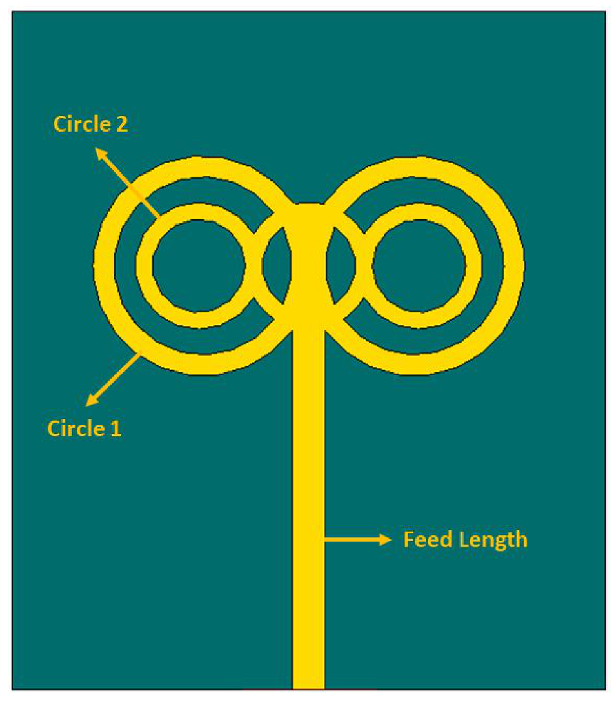
2. Antenna Design
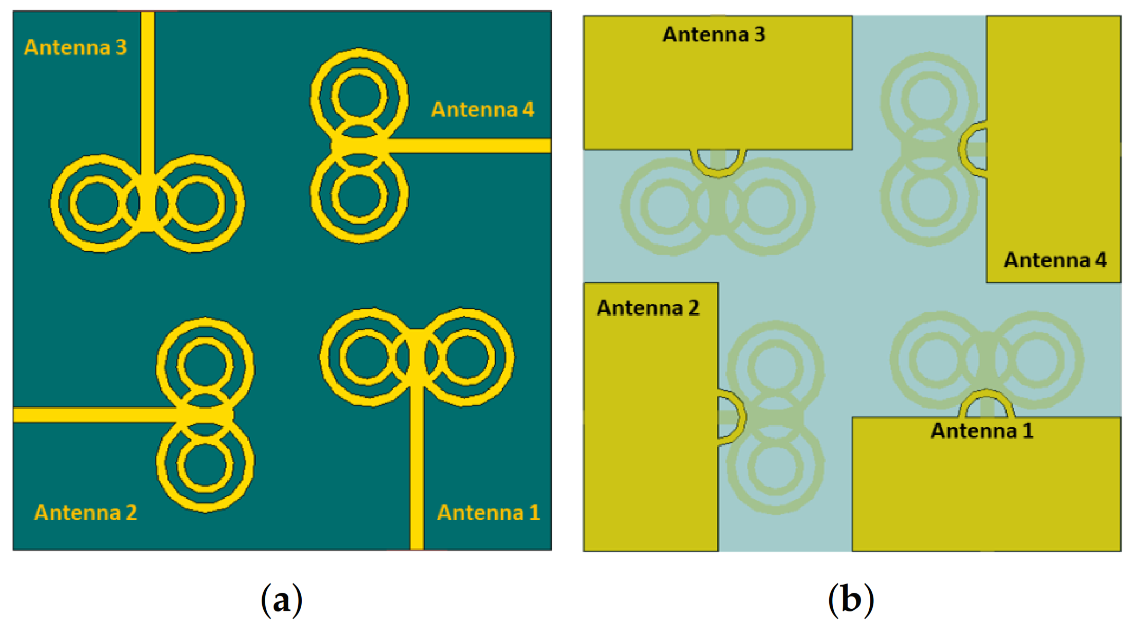
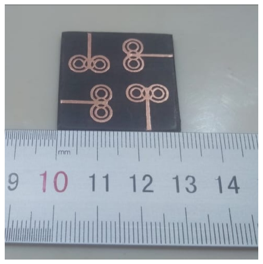
MIMO Configuration
3. Results and Discussion
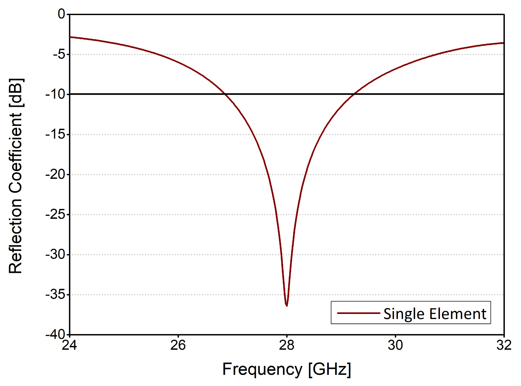
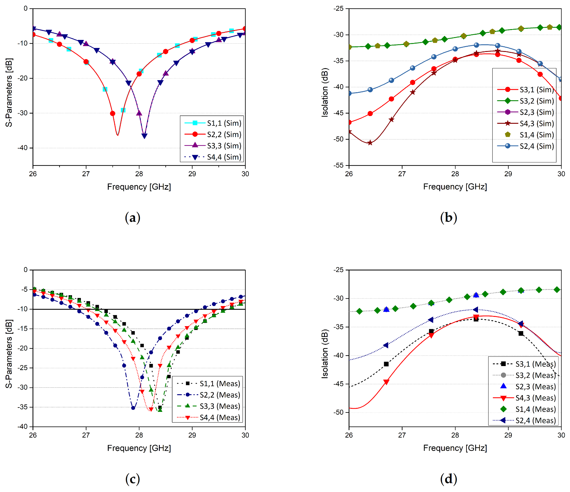
3.1. S Parameter Analysis
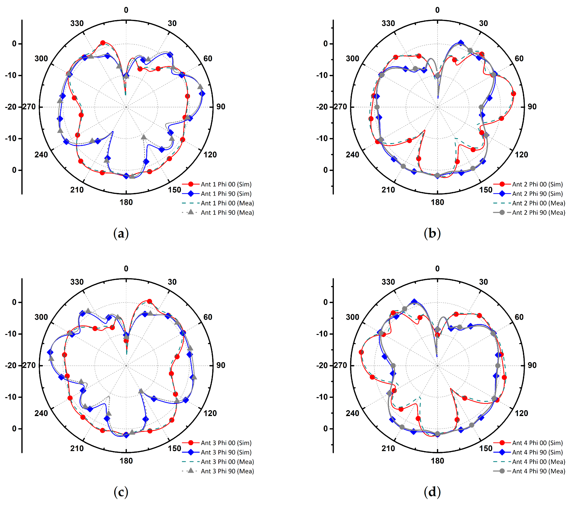
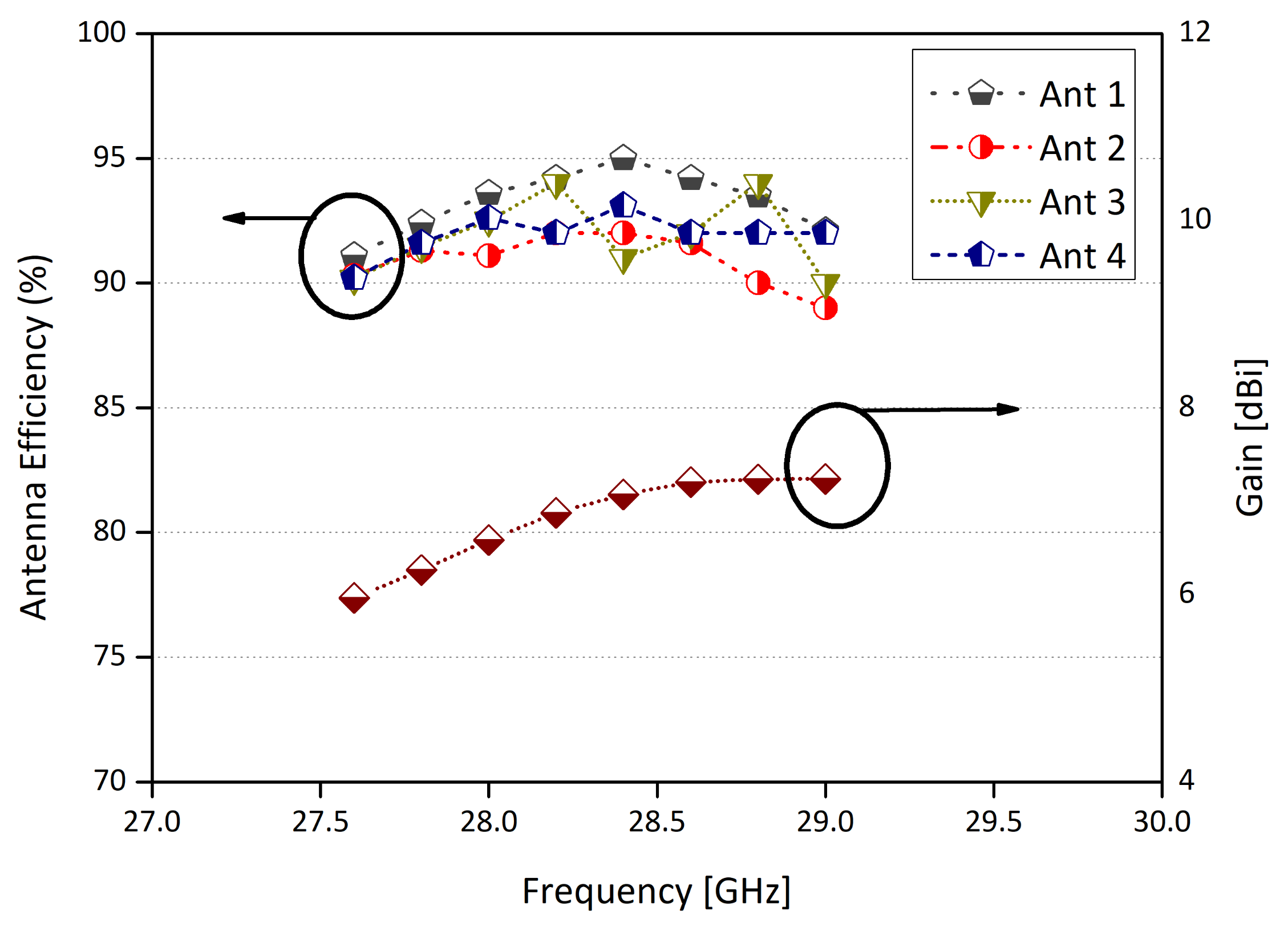
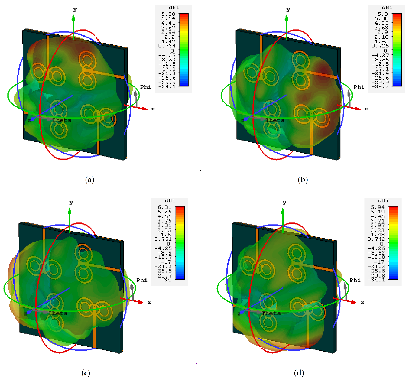
3.2. Radiation Pattern
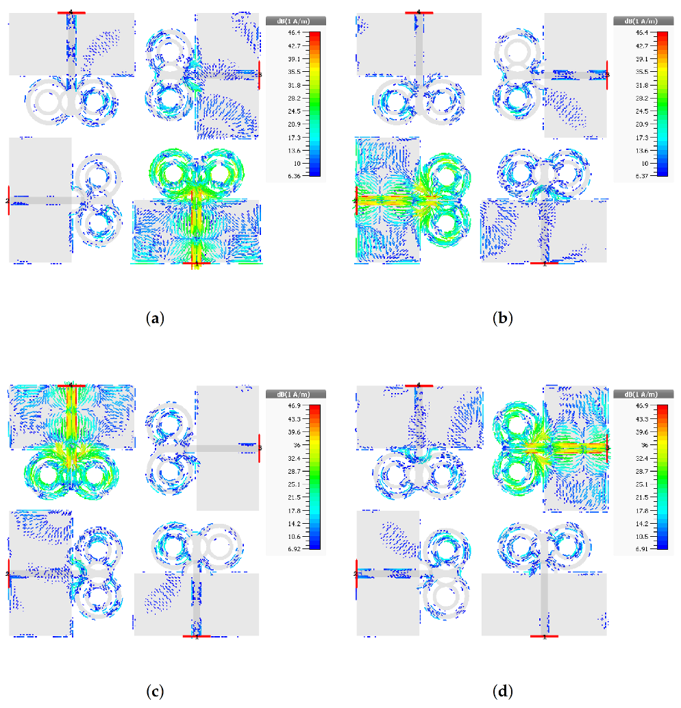
3.3. Surface Current Distributions
4. Mimo Parameters
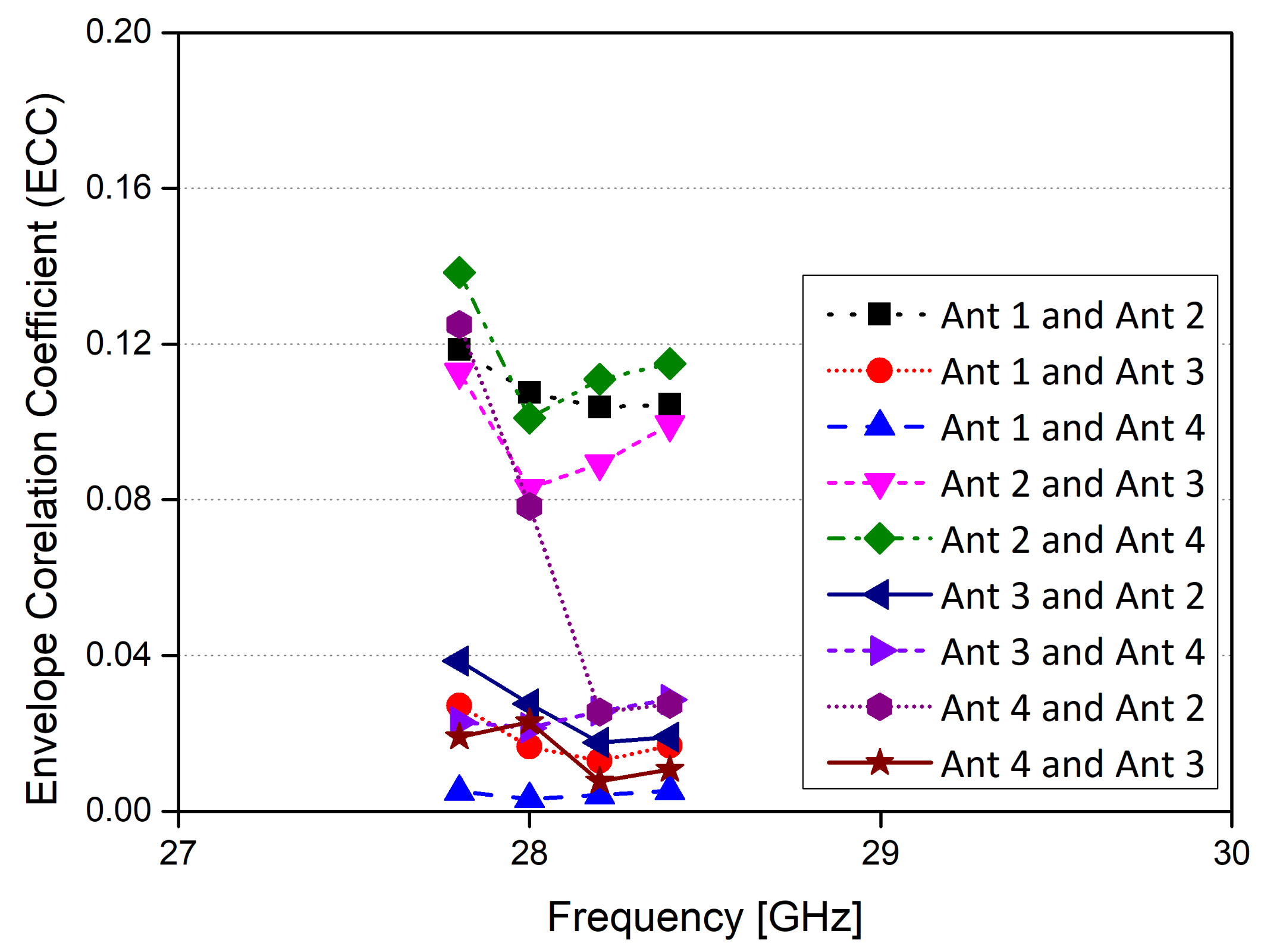
4.1. Envelope Correlation Coefficient
4.2. Mean Effective Gain (MEG)
5. Conclusions
Author Contributions
Funding
Data Availability Statement
Conflicts of Interest
References
- Varga, P.; Peto, J.; Franko, A.; Balla, D.; Haja, D.; Janky, F.; Soos, G.; Ficzere, D.; Maliosz, M.; Toka, L. 5g support for industrial iot applications–challenges, solutions, and research gaps. Sensors 2020, 20, 828. [Google Scholar] [CrossRef] [Green Version]
- Hilt, A. Availability and Fade Margin Calculations for 5G Microwave and Millimeter-Wave Anyhaul Links. Appl. Sci. 2019, 9, 5240. [Google Scholar] [CrossRef] [Green Version]
- Khalily, M.; Tafazolli, R.; Xiao, P.; Kishk, A.A. Broadband mm-wave microstrip array antenna with improved radiation characteristics for different 5G applications. IEEE Trans. Antennas Propag. 2018, 66, 4641–4647. [Google Scholar] [CrossRef]
- Abdullah, M.; Kiani, S.H.; Abdulrazak, L.F.; Iqbal, A.; Bashir, M.; Khan, S.; Kim, S. High-performance multiple-input multiple-output antenna system for 5G mobile terminals. Electronics 2019, 8, 1090. [Google Scholar] [CrossRef] [Green Version]
- Kiani, S.H.; Altaf, A.; Abdullah, M.; Muhammad, F.; Shoaib, N.; Anjum, M.R.; Damaševičius, R.; Blažauskas, T. Eight Element Side Edged Framed MIMO Antenna Array for Future 5G Smart Phones. Micromachines 2020, 11, 956. [Google Scholar] [CrossRef] [PubMed]
- Pi, Z.; Khan, F. An introduction to millimeter-wave mobile broadband systems. IEEE Commun. Mag. 2011, 49, 101–107. [Google Scholar] [CrossRef]
- Ullah, H.; Tahir, F.A. A Novel Snowflake Fractal Antenna for Dual-Beam Applications in 28 GHz Band. IEEE Access 2020, 8, 19873–19879. [Google Scholar] [CrossRef]
- NetWorld2020 ETP. 5G: Challenges, Research Priorities, and Recommendations; Joint White Paper. September 2014. Available online: https://networld2020.eu/wp-content/uploads/2015/01/Joint-Whitepaper-V12-clean-after-consultation.pdf (accessed on 6 January 2021).
- Shayea, I.; Rahman, T.A.; Azmi, M.H.; Islam, M.R. Real measurement study for rain rate and rain attenuation conducted over 26 GHz microwave 5G link system in Malaysia. IEEE Access 2018, 6, 19044–19064. [Google Scholar] [CrossRef]
- Aliakbari, H.; Abdipour, A.; Costanzo, A.; Masotti, D.; Mirzavand, R.; Mousavi, P. Performance investigation of space diversity for a 28/38 GHz MIMO antenna (applicable to mm-wave mobile network). In Proceedings of the 2016 Fourth International Conference on Millimeter-Wave and Terahertz Technologies (MMWaTT), Tehran, Iran, 20–22 December 2016; pp. 41–44. [Google Scholar]
- Sulyman, A.I.; Alwarafy, A.; MacCartney, G.R.; Rappaport, T.S.; Alsanie, A. Directional radio propagation path loss models for millimeter-wave wireless networks in the 28-, 60-, and 73-GHz bands. IEEE Trans. Wirel. Commun. 2016, 15, 6939–6947. [Google Scholar] [CrossRef]
- Zhang, J.; Ge, X.; Li, Q.; Guizani, M.; Zhang, Y. 5G millimeter-wave antenna array: Design and challenges. IEEE Wirel. Commun. 2016, 24, 106–112. [Google Scholar] [CrossRef]
- Wang, F.; Duan, Z.; Wang, X.; Zhou, Q.; Gong, Y. High Isolation Millimeter-Wave Wideband MIMO Antenna for 5G Communication. Int. J. Antennas Propag. 2019, 2019, 4283010. [Google Scholar] [CrossRef]
- Guo, J.; Cui, L.; Li, C.; Sun, B. Side-edge frame printed eight-port dual-band antenna array for 5G smartphone applications. IEEE Trans. Antennas Propag. 2018, 66, 7412–7417. [Google Scholar] [CrossRef]
- Yang, B.; Yu, Z.; Dong, Y.; Zhou, J.; Hong, W. Compact tapered slot antenna array for 5G millimeter-wave massive MIMO systems. IEEE Trans. Antennas Propag. 2017, 65, 6721–6727. [Google Scholar] [CrossRef]
- Sehrai, D.A.; Abdullah, M.; Altaf, A.; Kiani, S.H.; Muhammad, F.; Tufail, M.; Irfan, M.; Glowacz, A.; Rahman, S. A Novel High Gain Wideband MIMO Antenna for 5G Millimeter Wave Applications. Electronics 2020, 9, 1031. [Google Scholar] [CrossRef]
- Hussain, N.; Jeong, M.J.; Abbas, A.; Kim, N. Metasurface-based single-layer wideband circularly polarized MIMO antenna for 5G millimeter-wave systems. IEEE Access 2020, 8, 130293–130304. [Google Scholar] [CrossRef]
- Khan, J.; Sehrai, D.A.; Khan, M.A.; Khan, H.A.; Ahmad, S.; Ali, A.; Arif, A.; Memon, A.A.; Khan, S. Design and Performance Comparison of Rotated Y-Shaped Antenna Using Different Metamaterial Surfaces for 5G Mobile Devices. CMC-Comput. Mater. Contin. 2019, 60, 409–420. [Google Scholar] [CrossRef]
- Khan, J.; Sehrai, D.A.; Ali, U. Design of dual band 5G antenna array with SAR analysis for future mobile handsets. J. Electr. Eng. Technol. 2019, 14, 809–816. [Google Scholar] [CrossRef]
- Shoaib, N.; Shoaib, S.; Khattak, R.Y.; Shoaib, I.; Chen, X.; Perwaiz, A. MIMO antennas for smart 5G devices. IEEE Access 2018, 6, 77014–77021. [Google Scholar] [CrossRef]
- Iffat Naqvi, S.; Hussain, N.; Iqbal, A.; Rahman, M.; Forsat, M.; Mirjavadi, S.S.; Amin, Y. Integrated LTE and Millimeter-Wave 5G MIMO Antenna System for 4G/5G Wireless Terminals. Sensors 2020, 20, 3926. [Google Scholar] [CrossRef]
- Jilani, S.F.; Alomainy, A. Millimetre-wave T-shaped antenna with defected ground structures for 5G wireless networks. In Proceedings of the 2016 Loughborough Antennas & Propagation Conference (LAPC), Loughborough, UK, 14–16 November 2016; pp. 1–3. [Google Scholar]
- Khalid, M.; Iffat Naqvi, S.; Hussain, N.; Rahman, M.; Mirjavadi, S.S.; Khan, M.J.; Amin, Y. 4-Port MIMO antenna with defected ground structure for 5G millimeter wave applications. Electronics 2020, 9, 71. [Google Scholar] [CrossRef] [Green Version]
- Wani, Z.; Abegaonkar, M.P.; Koul, S.K. A 28-GHz antenna for 5G MIMO applications. Prog. Electromagn. Res. 2018, 78, 73–79. [Google Scholar] [CrossRef] [Green Version]
- Ojaroudi Parchin, N.; Jahanbakhsh Basherlou, H.; Alibakhshikenari, M.; Ojaroudi Parchin, Y.; Al-Yasir, Y.I.; Abd-Alhameed, R.A.; Limiti, E. Mobile-phone antenna array with diamond-ring slot elements for 5G massive MIMO systems. Electronics 2019, 8, 521. [Google Scholar] [CrossRef] [Green Version]
- Al Abbas, E.; Ikram, M.; Mobashsher, A.T.; Abbosh, A. MIMO Antenna System for Multi-Band Millimeter-Wave 5G and Wideband 4G Mobile Communications. IEEE Access 2019, 7, 181916–181923. [Google Scholar] [CrossRef]
- Naqvi, S.I.; Naqvi, A.H.; Arshad, F.; Riaz, M.A.; Azam, M.A.; Khan, M.S.; Amin, Y.; Loo, J.; Tenhunen, H. An integrated antenna system for 4G and millimeter-wave 5G future handheld devices. IEEE Access 2019, 7, 116555–116566. [Google Scholar] [CrossRef]
- Ikram, M.; Nguyen-Trong, N.; Abbosh, A. Multiband MIMO microwave and millimeter antenna system employing dual-function tapered slot structure. IEEE Trans. Antennas Propag. 2019, 67, 5705–5710. [Google Scholar] [CrossRef]
- Tu, D.T.T.; Thang, N.G.; Ngoc, N.T.; Phuong, N.T.B.; Van Yem, V. 28/38 GHz dual-band MIMO antenna with low mutual coupling using novel round patch EBG cell for 5G applications. In Proceedings of the 2017 International Conference on Advanced Technologies for Communications (ATC), Quy Nhon, Vietnam, 18–20 October 2017; pp. 64–69. [Google Scholar]
- Marzouk, H.M.; Ahmed, M.I.; Shaalan, A.H.A.M. Novel dual-band 28/38 GHz MIMO antennas for 5G mobile applications. Prog. Electromagn. Res. 2019, 93, 103–117. [Google Scholar] [CrossRef] [Green Version]
- Liu, Y.; Li, Y.; Ge, L.; Wang, J.; Ai, B. A Compact Hepta-Band Mode-Composite Antenna for Sub (6, 28, and 38) GHz Applications. IEEE Trans. Antennas Propag. 2020, 68, 2593–2602. [Google Scholar] [CrossRef]
- Sunthari, P.M.; Veeramani, R. Multiband microstrip patch antenna for 5G wireless applications using MIMO techniques. In Proceedings of the 2017 First International Conference on Recent Advances in Aerospace Engineering (ICRAAE), Coimbatore, India, 3–4 March 2017; pp. 1–5. [Google Scholar]
- Marzouk, H.; Ahmed, M.; Shaalan, A. A Novel Dual-band 28/38 GHz Slotted Microstip MIMO Antenna for 5G Mobile Applications. In Proceedings of the 2019 IEEE International Symposium on Antennas and Propagation and USNC-URSI Radio Science Meeting, Atlanta, GA, USA, 7–12 July 2019; pp. 607–608. [Google Scholar]
- Ali, W.; Das, S.; Medkour, H.; Lakrit, S. Planar dual-band 27/39 GHz millimeter-wave MIMO antenna for 5G applications. Microsyst. Technol. 2020, 1–10. [Google Scholar] [CrossRef]


| Frequency (GHz) | MEG1 (dB) | MEG2 (dB) | MEG3 (dB) | MEG4 (dB) |
|---|---|---|---|---|
| 28 | −4.1 | −3.9 | −3.2 | −3.1 |
| 28.5 | −3.09 | −2.87 | −3.5 | −3.4 |
| 29 | −2.9 | −3.02 | −2.8 | −3.4 |
| Ref. | Ports | Size of Antenna in mm | Isolation | Eff. | Gain | ECC |
|---|---|---|---|---|---|---|
| (LxW) | (dB) | % | (dBi) | |||
| [4] | 6 | 136 × 68 | −10 | 50 | 3.9 | <0.3 |
| [5] | 8 | 150 × 75 | −12.5 | 70 | 4.9 | <0.15 |
| [30] | 4 | 55 × 110 | −28.32 | 88.25 | 8.27 | <0.047 |
| [31] | 3 | 130 × 80 | −53 | 80 | 10.3 | N/A |
| [32] | 4 | 26.6 × 3.25 | N/A | N/A | 5.2 | N/A |
| [29] | 4 | 19.25 × 26 | −25 | 86 | 5.72 | <0.04 |
| [33] | 2 | 55 × 110 | −27.3 | N/A | 9.49 | <0.06 |
| [34] | 2 | 26 × 11 | −25 | 98.6 | 5.7 | <0.01 |
| Proposed | 4 | 30 × 30 | <−29 | 92 | 6.1 | <0.16 |
Publisher’s Note: MDPI stays neutral with regard to jurisdictional claims in published maps and institutional affiliations. |
© 2021 by the authors. Licensee MDPI, Basel, Switzerland. This article is an open access article distributed under the terms and conditions of the Creative Commons Attribution (CC BY) license (http://creativecommons.org/licenses/by/4.0/).
Share and Cite
Kamal, M.M.; Yang, S.; Ren, X.-c.; Altaf, A.; Kiani, S.H.; Anjum, M.R.; Iqbal, A.; Asif, M.; Saeed, S.I. Infinity Shell Shaped MIMO Antenna Array for mm-Wave 5G Applications. Electronics 2021, 10, 165. https://0-doi-org.brum.beds.ac.uk/10.3390/electronics10020165
Kamal MM, Yang S, Ren X-c, Altaf A, Kiani SH, Anjum MR, Iqbal A, Asif M, Saeed SI. Infinity Shell Shaped MIMO Antenna Array for mm-Wave 5G Applications. Electronics. 2021; 10(2):165. https://0-doi-org.brum.beds.ac.uk/10.3390/electronics10020165
Chicago/Turabian StyleKamal, Mian Muhammad, Shouyi Yang, Xin-cheng Ren, Ahsan Altaf, Saad Hassan Kiani, Muhammad Rizwan Anjum, Amjad Iqbal, Muhammad Asif, and Sohail Imran Saeed. 2021. "Infinity Shell Shaped MIMO Antenna Array for mm-Wave 5G Applications" Electronics 10, no. 2: 165. https://0-doi-org.brum.beds.ac.uk/10.3390/electronics10020165