Correction: Balasubramanian et al. Approximate Array Multipliers. Electronics 2021, 10, 630


School of Computer Science and Engineering, Nanyang Technological University, 50 Nanyang Avenue, Singapore 639798, Singapore
*
Author to whom correspondence should be addressed.
Electronics 2021, 10(20), 2460; https://0-doi-org.brum.beds.ac.uk/10.3390/electronics10202460
Submission received: 17 August 2021
/
Accepted: 16 September 2021
/
Published: 11 October 2021
(This article belongs to the Section Circuit and Signal Processing)
The authors wish to correct the mistakes in Figures 3a and 4a,b of the article [1] and present the correct versions. The authors confirm that the corrections are confined to just Figures 3 and 4 and do not affect the results presented in Tables 1 and 2, and Figures 6 to 10 of the article. The reason for the mistakes is, as a part of the research, several new approximate array multipliers were designed and analyzed, and a few figures inadvertently got mixed up during the paper preparation which are corrected now.
Error in Figure 3.
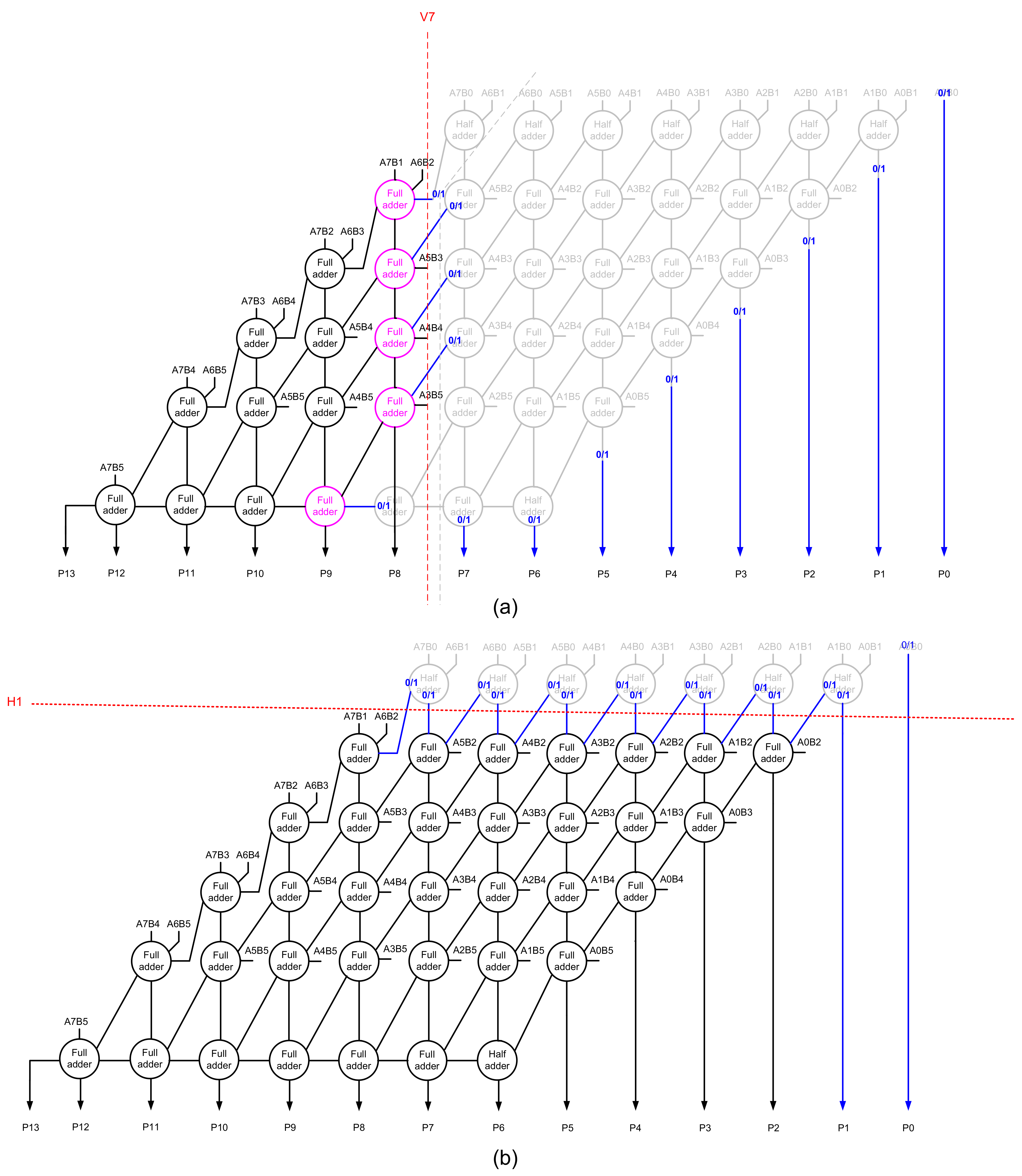
In the original article, there was a mistake in Figure 3a as published, presented on the next page. After making a vertical cut, V7, on an accurate array multiplier, as shown in Figure 2a of the paper, Figure 3a results. In Figure 3a, the full adder producing product bit P9 has one of its inputs cut since the full adder preceding it is eliminated. Therefore, the full adder producing product bit P9 has only two inputs, and it can be reduced to a half adder; hence, a need does not arise for providing a constant 0/1 input to it as shown in Figure 3a. Further, the dashed line in light gray that appears adjacent to vertical cut V7 in Figure 3a was included by mistake and is not necessary.
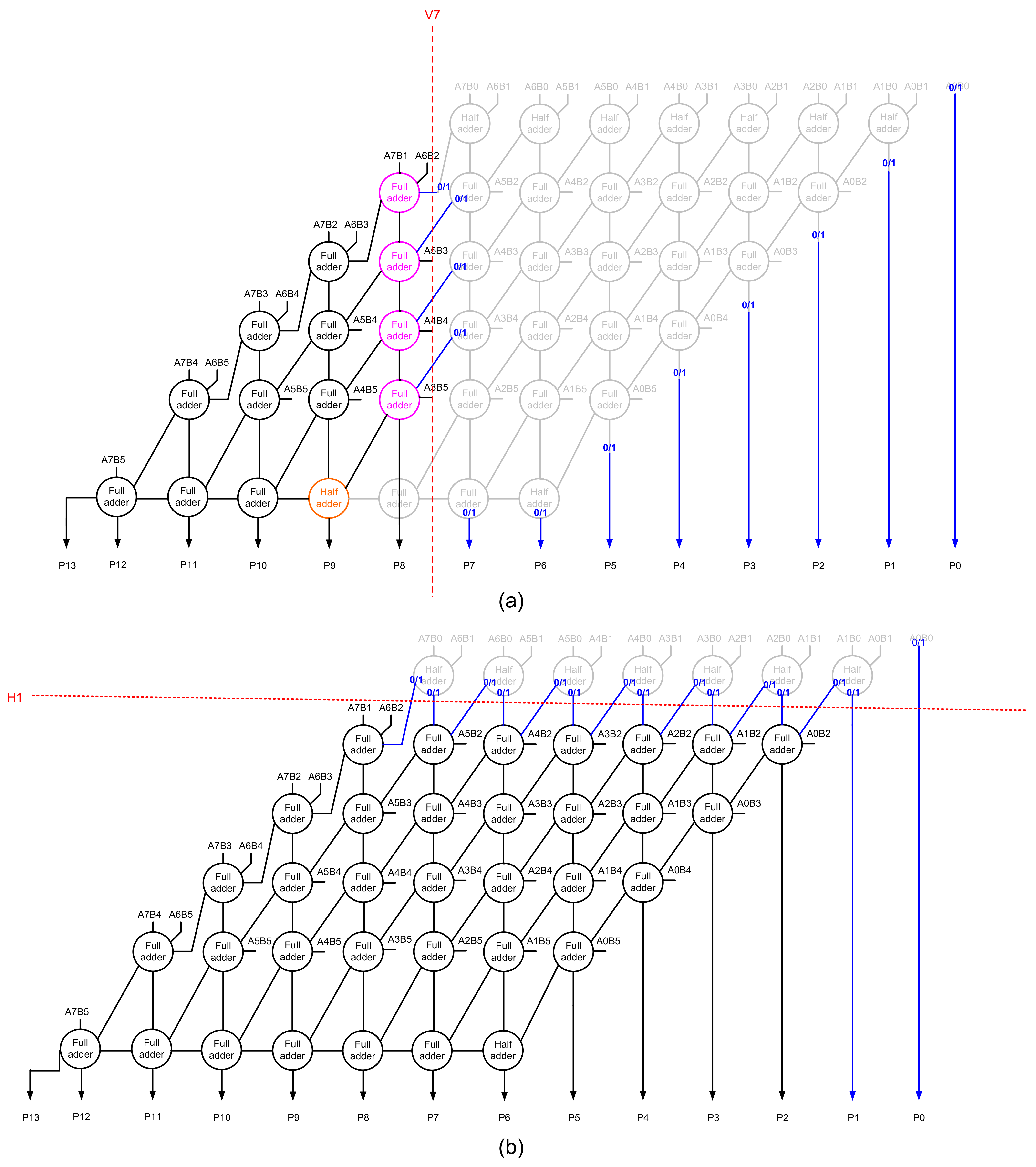
The corrected Figure 3a, which forms a part of Figure 3, is shown on the next page. The authors confirm that the results presented in Tables 1 and 2 and elsewhere correspond to the correct version of Figure 3a. The full adder producing product bit P9 with one of its inputs assigned a 0 in the earlier version is now replaced by a half adder that is highlighted in orange in the correct version of Figure 3a shown below.
Error in Figure 4.
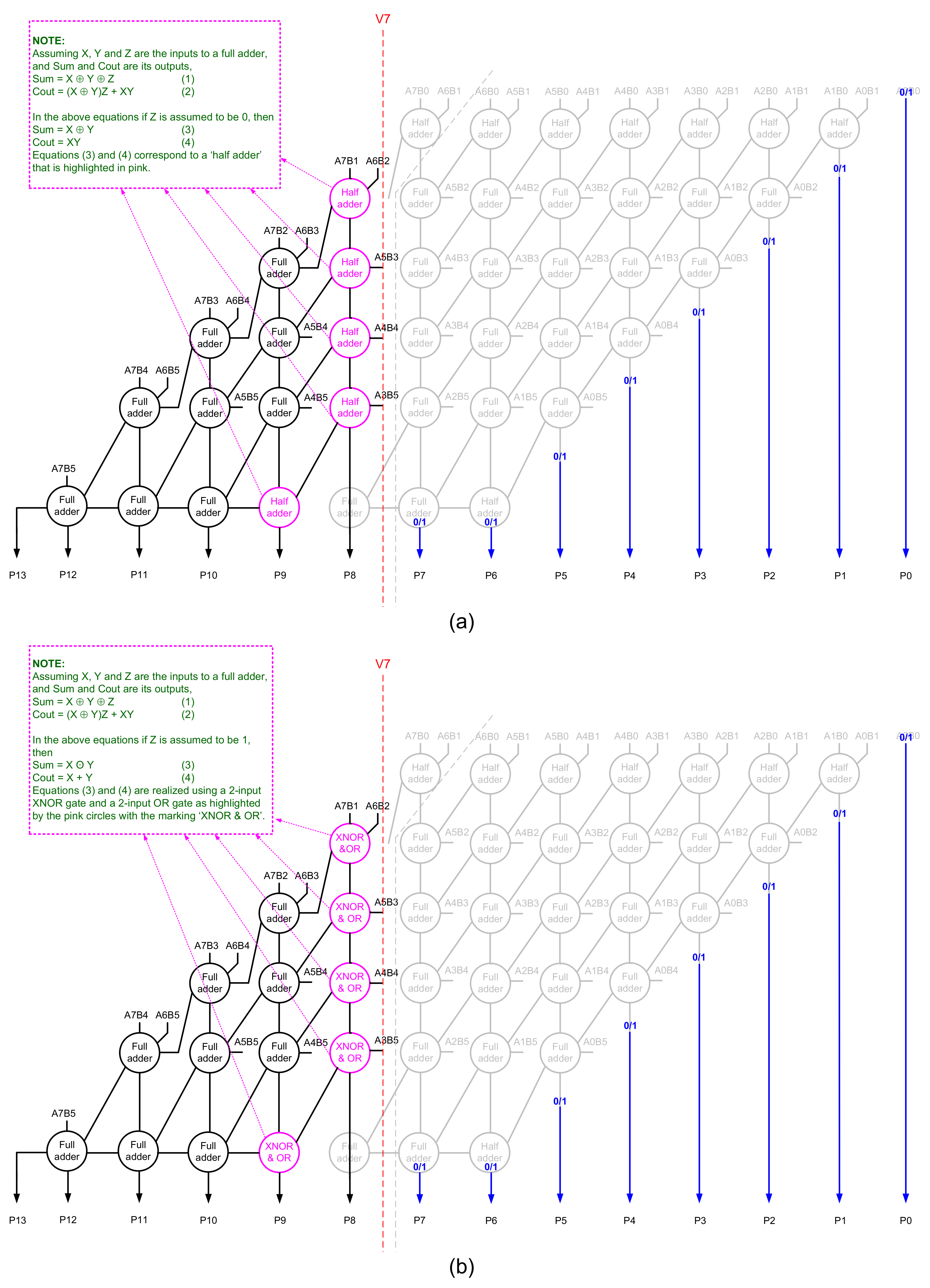
In the original article, there were mistakes in Figure 4a,b as published, shown on the next page. These mistakes were a direct consequence of the mistake made in Figure 3a, discussed previously, which got carried over to Figure 4a,b as well. This is because Figure 4a,b are derived from Figure 3a by assigning respective internal inputs of 0 and 1 to the full adders highlighted in pink. Further, the dashed line in light gray that appears adjacent to vertical cut V7 in Figure 4a,b were included by mistake and are not necessary.
The corrected Figure 4a,b are shown below. The authors confirm that the results presented in Tables 1 and 2 and elsewhere correspond to the correct version of Figure 4a,b.
Referring to the correct version of Figure 3a, shown on page 3, only four full adders are highlighted in pink. When one of the inputs to these full adders is assigned a binary 0, they are transformed into half adders which are shown in pink in the correct Figure 4a on the previous page. On the contrary, if one of the inputs to the full adders highlighted in pink in the correct Figure 3a is assigned a binary 1, each of those full adders is transformed into a combination of a two-input XNOR gate and a two-input OR gate, shown in pink in the correct Figure 4b on the previous page, where the XNOR gate produces an approximate sum output, and the OR gate produces an approximate carry output.
Funding
This research was funded by the Ministry of Education, Singapore under grant number MOE2018-T2-2-024.
Reference
- Balasubramanian, P.; Nayar, R.; Maskell, D.L. Approximate array multipliers. Electronics 2021, 10, 630. [Google Scholar] [CrossRef]
Figure 3.
Illustrating the effect of example vertical and horizontal cuts on an accurate array multiplier resulting in approximate array multipliers. (a) Vertical cut V7; (b) horizontal cut H1. The circuit portions eliminated are shown in light gray.
Figure 3.
Illustrating the effect of example vertical and horizontal cuts on an accurate array multiplier resulting in approximate array multipliers. (a) Vertical cut V7; (b) horizontal cut H1. The circuit portions eliminated are shown in light gray.

Figure 3.
Illustrating the effect of example vertical and horizontal cuts on an accurate array multiplier resulting in approximate array multipliers. (a) Vertical cut V7; (b) horizontal cut H1. The circuit portions eliminated are shown in light gray.
Figure 3.
Illustrating the effect of example vertical and horizontal cuts on an accurate array multiplier resulting in approximate array multipliers. (a) Vertical cut V7; (b) horizontal cut H1. The circuit portions eliminated are shown in light gray.

Figure 4.
Logic optimization of an approximate array multiplier (obtained through vertical cut V7) based on the assignment of: (a) a 0 input assigned to the full adders highlighted in pink in Figure 3a; (b) a 1 input assigned to the full adders highlighted in pink in Figure 3a.

Figure 4.
Logic optimization of an approximate array multiplier (obtained through vertical cut V7) based on the assignment of: (a) a 0 input assigned to the full adders highlighted in pink in the correct Figure 3a; (b) a 1 input assigned to the full adders highlighted in pink in the correct Figure 3a.

Publisher’s Note: MDPI stays neutral with regard to jurisdictional claims in published maps and institutional affiliations. |
© 2021 by the authors. Licensee MDPI, Basel, Switzerland. This article is an open access article distributed under the terms and conditions of the Creative Commons Attribution (CC BY) license (https://creativecommons.org/licenses/by/4.0/).
Share and Cite
MDPI and ACS Style
Balasubramanian, P.; Nayar, R.; Maskell, D.L. Correction: Balasubramanian et al. Approximate Array Multipliers. Electronics 2021, 10, 630. Electronics 2021, 10, 2460. https://0-doi-org.brum.beds.ac.uk/10.3390/electronics10202460
AMA Style
Balasubramanian P, Nayar R, Maskell DL. Correction: Balasubramanian et al. Approximate Array Multipliers. Electronics 2021, 10, 630. Electronics. 2021; 10(20):2460. https://0-doi-org.brum.beds.ac.uk/10.3390/electronics10202460
Chicago/Turabian StyleBalasubramanian, Padmanabhan, Raunaq Nayar, and Douglas L. Maskell. 2021. "Correction: Balasubramanian et al. Approximate Array Multipliers. Electronics 2021, 10, 630" Electronics 10, no. 20: 2460. https://0-doi-org.brum.beds.ac.uk/10.3390/electronics10202460
Note that from the first issue of 2016, this journal uses article numbers instead of page numbers. See further details here.