1. Introduction
In recent years, the development of modern wireless systems caused interest in advanced antenna technology, among which multibeam antennas that offer multiple independent beams can be distinguished. The concept of multibeam antennas was introduced by Shelton [
1] and has become the subject of extensive research up to date [
2,
3,
4]. Multibeam antenna arrays can be realized with the use of beamforming networks, such as Butler matrices, which ensure an appropriate signal distribution across the array [
5]. Although there are many reported solutions that involve Butler matrices realized in different technologies, most of them are focused on narrowband concepts [
6,
7,
8,
9]. On the other hand, the constant development of communication systems calls for more advanced solutions, such as multiband or broadband networks. Therefore, the concept of scalable antenna arrays has recently gained a lot of interest [
10,
11,
12,
13,
14,
15,
16], since such arrays allow the assumed antenna parameters to be achieved, i.e., beamwidth or beam direction in a very broad bandwidth. In the literature, some concepts of scalable antenna arrays with constant broadside beam can be found [
13,
17,
18] which are realized with the use of frequency-dependent feeding networks, whereas multi-beam antenna arrays with almost constant multiple beam patterns are rarely reported. This is due to the required distance between radiating elements which has to be kept around 0.5 λ and appropriate signal distribution, which has to be ensured across the array in a broad bandwidth. Although broadband Butler matrices are known [
19,
20], the required spacing between radiating elements causes that dual-band concepts often involve separate antenna arrays operating in each sub-band [
21,
22], whereas solutions that allow constant broad frequency range to be covered are rarely reported. One exemplary solution is described in [
23], where multibeam antennas operating in an octave frequency range have been described. In this concept, frequency-dependent Butler matrices change their orders from
N to
N/2 as the frequency increases. As shown, multiple-beam radiation patterns can be achieved with such a beamforming network. As presented, even wider bandwidths can be achieved by the utilization of modified Butler matrices which change their behavior three times across the operational frequency range [
24]. However, the major drawback of these solutions is the complexity of the applied beamforming networks, which limits the applicability of the described concepts [
23,
24]. A simpler approach to the realization of scalable multibeam antennas is presented in [
25], where the feeding network consists of a broadband quadrature directional coupler and frequency-dependent power dividers. As shown, this allows an attractive two-beam radiation pattern to be achieved over the frequency range reaching
fH/
fL = 3. However, the solution proposed in [
25] can be implemented only in two-beam antenna arrays and cannot be straightforwardly extended to antenna arrays with a higher number of beams.
In this paper, we present a novel concept of the multi-beam antenna arrays that allows a four-beam radiation pattern to be achieved over a one-octave frequency range. The proposed feeding network consists of a broadband Butler matrix at the outputs to which an appropriate feeding network based on directional filters is connected. Such a solution provides attractive four-beam radiation properties over a very broad bandwidth. Simultaneously, it leads to a simpler feeding network comparing to the previously developed concept [
23], since the classic broadband Butler matrices are well developed and the required directional filters are relatively easy to design. The proposed concept was verified by the design and measurements of two four-beam antenna arrays operating in a 2–4 GHz frequency range and consisting of eight and twelve radiating elements, respectively.
2. Concept of Octave-Band Four-Beam Antenna Arrays
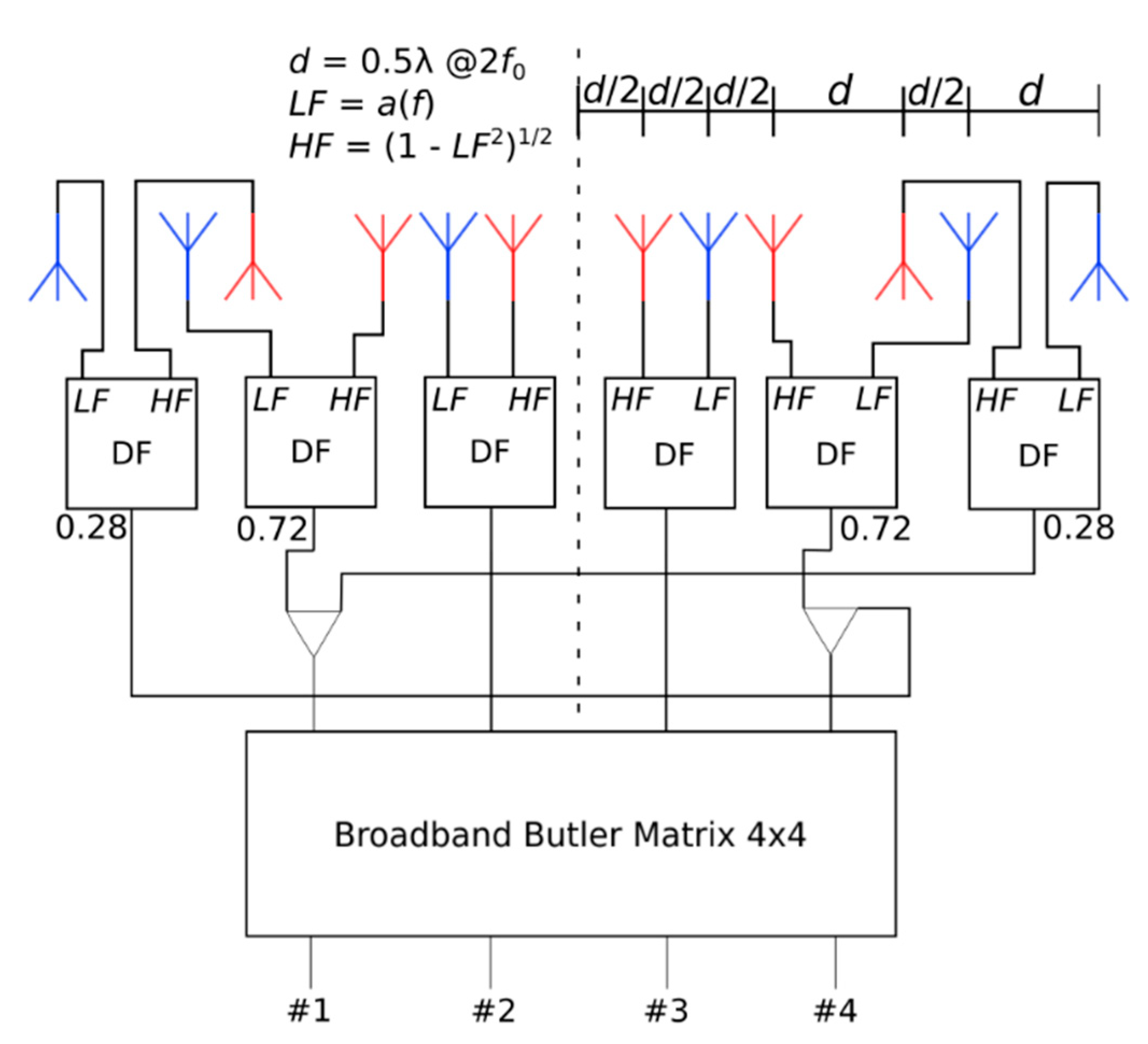
A concept of the proposed scalable four-beam antenna array is explained in
Figure 1. It is based on [
25]; however, there are substantial differences between these two approaches. First of all, the antenna array described in [
25] utilizes four equally spaced broadband radiating elements. The distance between two inner elements at a higher frequency is equal to the one for two outer elements at a lower frequency; therefore, the frequency ratio in this case equals
fH/
fL = 3. This means that the concept described in [
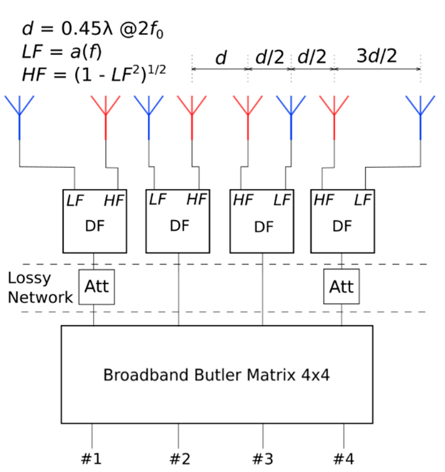
25] is only reserved for two-beam antenna arrays. Therefore, in this paper, we propose a novel approach, in which the radiating elements are not equally distributed across the array, as shown in
Figure 1. In particular, the distance between the two elements operating at the lowest and highest frequencies (radiating elements marked in blue and red colors) is equal to half (or 3/2 times) the distance between two inner elements (two middle radiating elements marked in red). This implies that the relative distance among all elements operating at a lower frequency is exactly the same as the one among the ones operating at a higher frequency when the frequency ratio is equal to
fH/
fL = 2. Such radiating elements’ distribution allows scalable four-beam antenna arrays to be realized when appropriate modifications of the amplitude excitation are applied, as it is explained in detail below.
To generate a multiple beam radiation pattern, a broadband 4 × 4 Butler matrix together with four directional filters (DF) is utilized, as shown in
Figure 1. The Butler matrix ensures appropriate amplitude and phase distribution between each pair of radiating elements that operate at high and low frequency ranges, whereas directional filters realize smooth signal switching between these elements. This implies that a similar radiation pattern can be obtained over the entire bandwidth from
fL to
fH (equal to 2
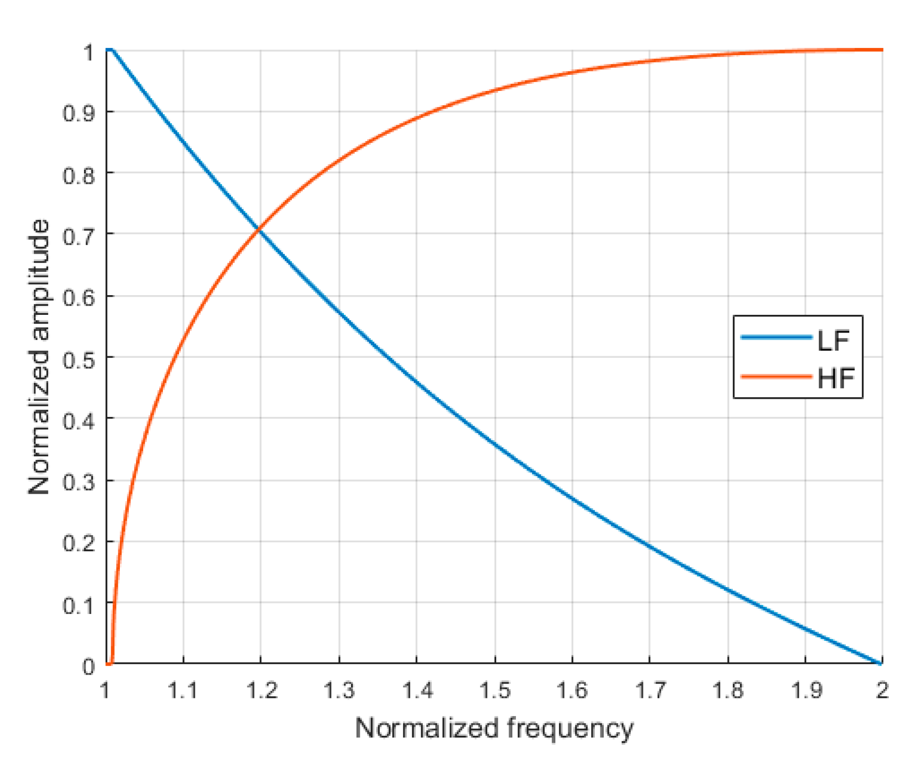
fL). The proposed antenna array was analyzed with the use of numerical optimization and the frequency characteristics of the required directional filters were found. The optimization process focused on achieving the minimum beamwidth variation together with the minimum variation of all beams’ directions. The resulting switching function is shown in
Figure 2, which shows the amplitude delivered to each of the radiating elements operating at the lowest frequency (marked as
LF) together with the amplitude delivered to each radiating elements operating at the highest frequency range (marked as
HF). As can be seen, the signal is smoothly switched between the lowest and highest frequency outputs of the directional filters across the bandwidth (see
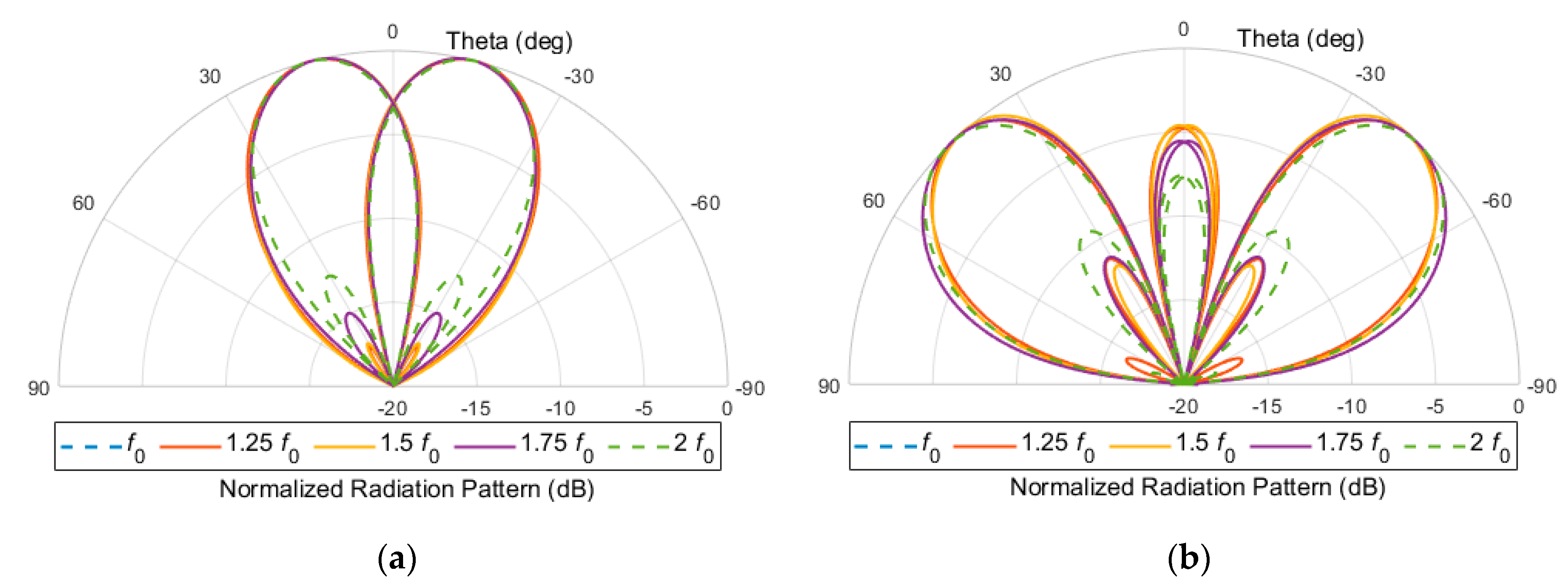
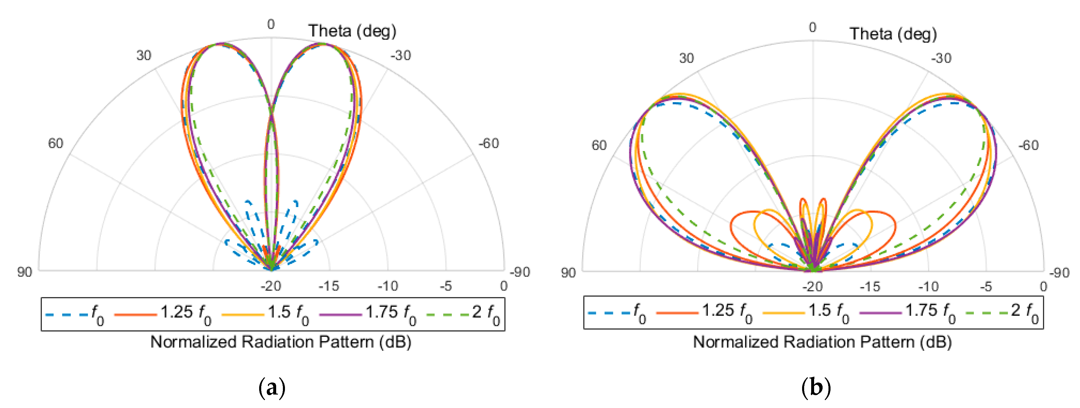
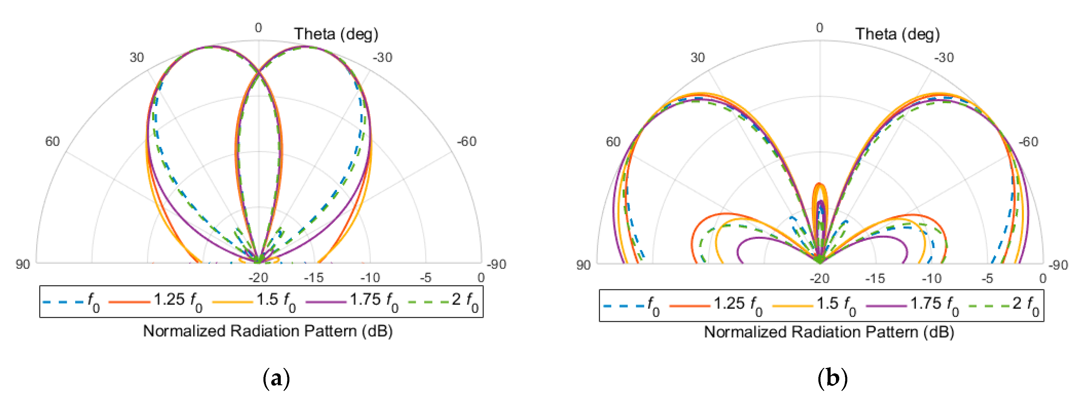
Figure 1). The optimization process reveals that, although it is possible to achieve an almost constant beam pattern across such a broad bandwidth, the relative sidelobe level reaches about −4 dB for such an array when the directivity of the single radiating element is taken into account. This is illustrated in
Figure 3, where calculation results are shown assuming that the utilized radiating element is directive with its radiation pattern described by the approximate function cos
1.3(
θ). As can be seen, the two outer beams (2L and 2R beams) feature very low sidelobe levels reaching −4 dB. This is due to the fact that the angles at which the array factor has its maximum, the single radiating element features a severe attenuation; therefore, the relative sidelobe level raises.
Therefore, in this paper, we propose the application of unequal power distribution to overcome this problem, which allows us to achieve a good radiation pattern. This is another substantial difference between this concept and the one presented in [
25]. The tapered excitation across the proposed scalable antenna array can be achieved in either lossy or theoretically lossless networks. The first approach mentioned is illustrated in
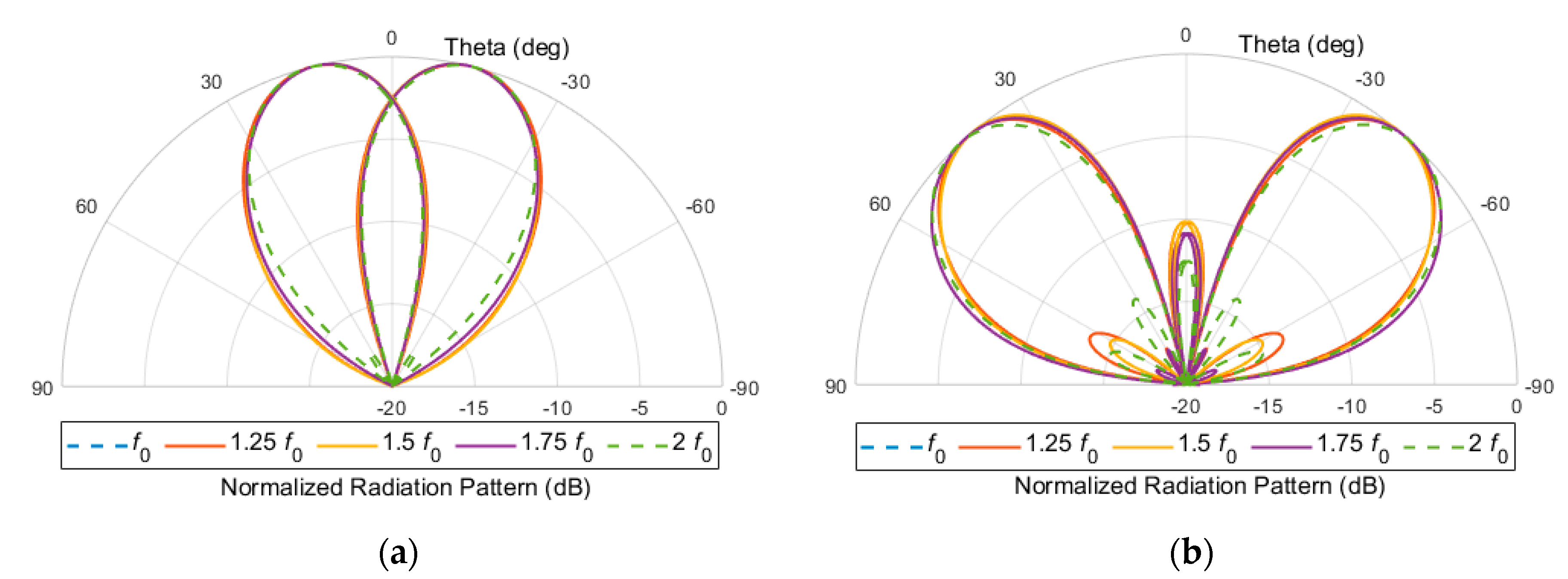
Figure 1, in which additional attenuators (Att) are applied in the outer channels between the applied Butler matrix and the four directional filters. By controlling the attenuation level of these two attenuators, it is possible to achieve tapered excitation across the entire antenna array. It has to be underlined that, by introducing only 1.25 dB of attenuation of the total signal resulted in the application of 3 dB attenuators in the outer channels, it is possible to improve the overall radiation pattern. The calculated radiation pattern is shown in
Figure 4. As can be seen, the proposed method allows sidelobe level, which is now better than −10 dB, to be improved.
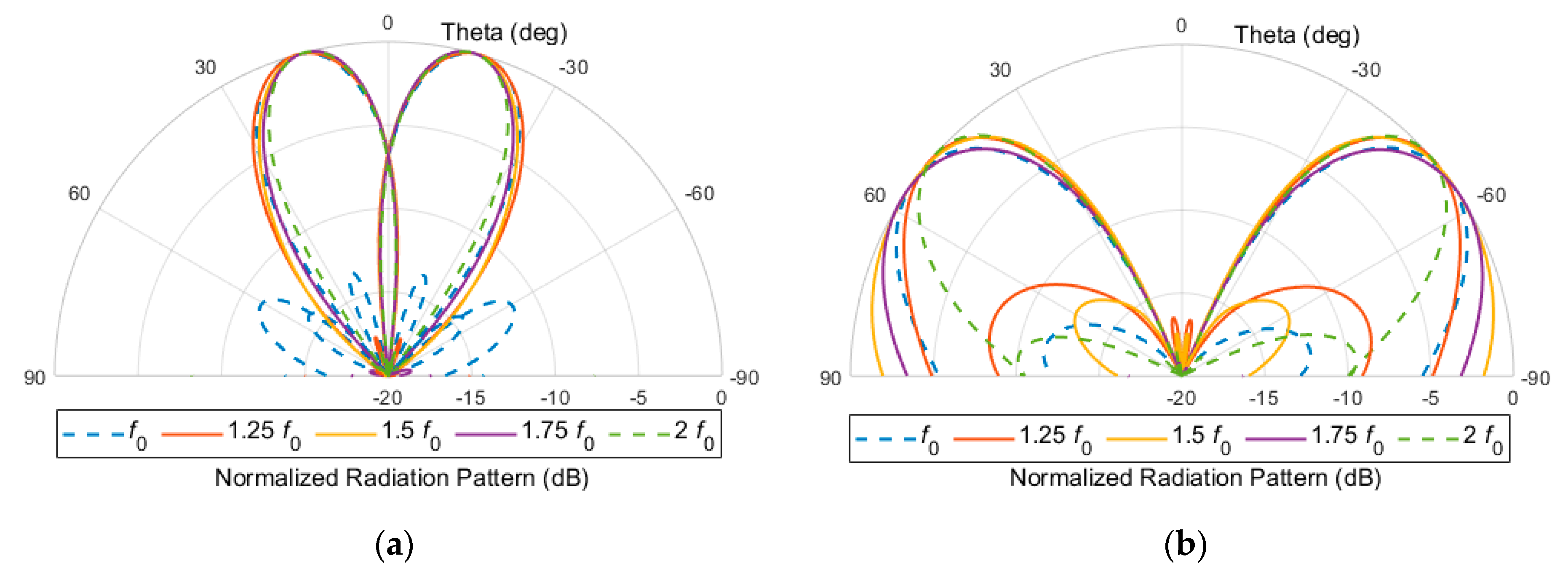
The second possible approach which allows to minimize the sidelobe level of the resulting antenna array with a theoretically lossless network is based on the concept proposed in [
6] and further developed in [
7]. The schematic diagram of the proposed scalable antenna array is shown in
Figure 5. As seen in this concept, twelve radiating elements are used to achieve taper excitation across the array and additional unequal power dividers having a power division ratio of 1:2.6 are applied, whereas, to achieve appropriate phase distributions, the selected four radiating elements are rotated, which ensures an ideal 180° phase shift. Moreover, the two outer elements operating at the lower frequency range marked in red color in
Figure 5 are placed closer to reduce the directivity of the entire antenna array; therefore, they minimize the resulting grating lobe. Such modifications resulted in the scalable antenna array having the radiation pattern shown in
Figure 6. As seen also in this case, a significant sidelobe reduction is achieved; however, the larger difference in beamwidths of the two outer beams that can be observed is caused by the high directivity of the entire antenna array, which is composed of twelve radiating elements.
3. Design and Realization of Octave-Band Four-Beam Antenna Arrays
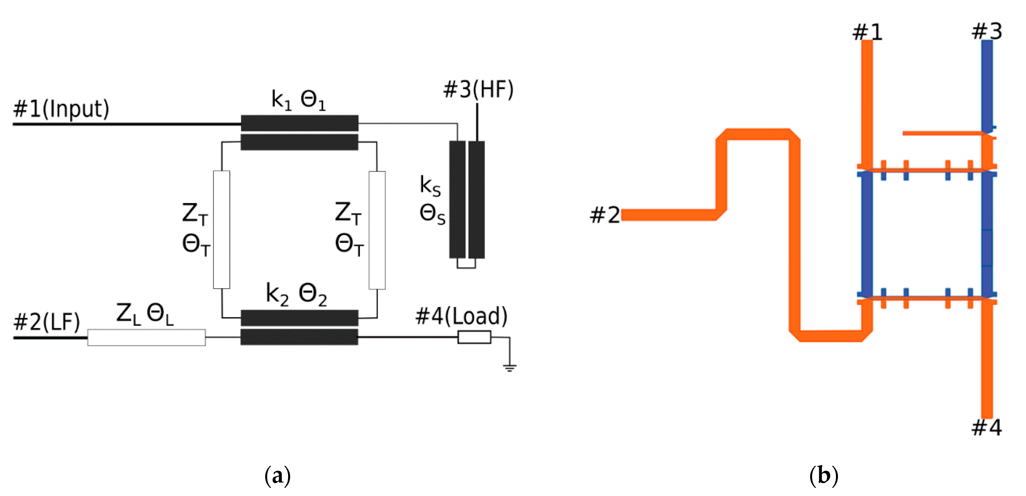
Both the proposed concepts were verified by the design and realization of four-beam antenna arrays operating in a 2–4 GHz frequency range. First, a directional filter that features the desired switching function was designed, since, among different approaches to achieve the required switching functionality, such a circuit provides the simplest solution. The proposed schematic diagram and layout of the designed filter are shown in
Figure 7. As can be seen, it consists of a circuit composed of two coupled-line sections with two quarter-wave transmission lines in-between. Moreover, at one of the outputs, a Schiffman C-section is added to equalize the differential phase response between the two outputs of the directional filter. The parameters of the designed directional filter are summarized in
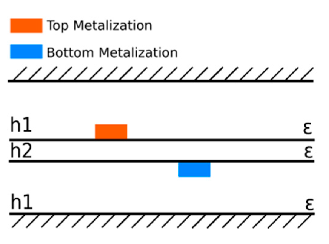
Table 1. The designed directional filter was realized in a homogeneous symmetric stripline structure shown schematically in
Figure 8, in which a thin laminate layer having thickness
h2 = 0.1 mm was inserted between two thick laminate layers having thicknesses
h1 = 1.52 mm. All layers have the same dielectric constant equal to ε
r = 3.38. The designed directional filter was manufactured and measured. The obtained results in comparison with the electromagnetically calculated ones are shown in
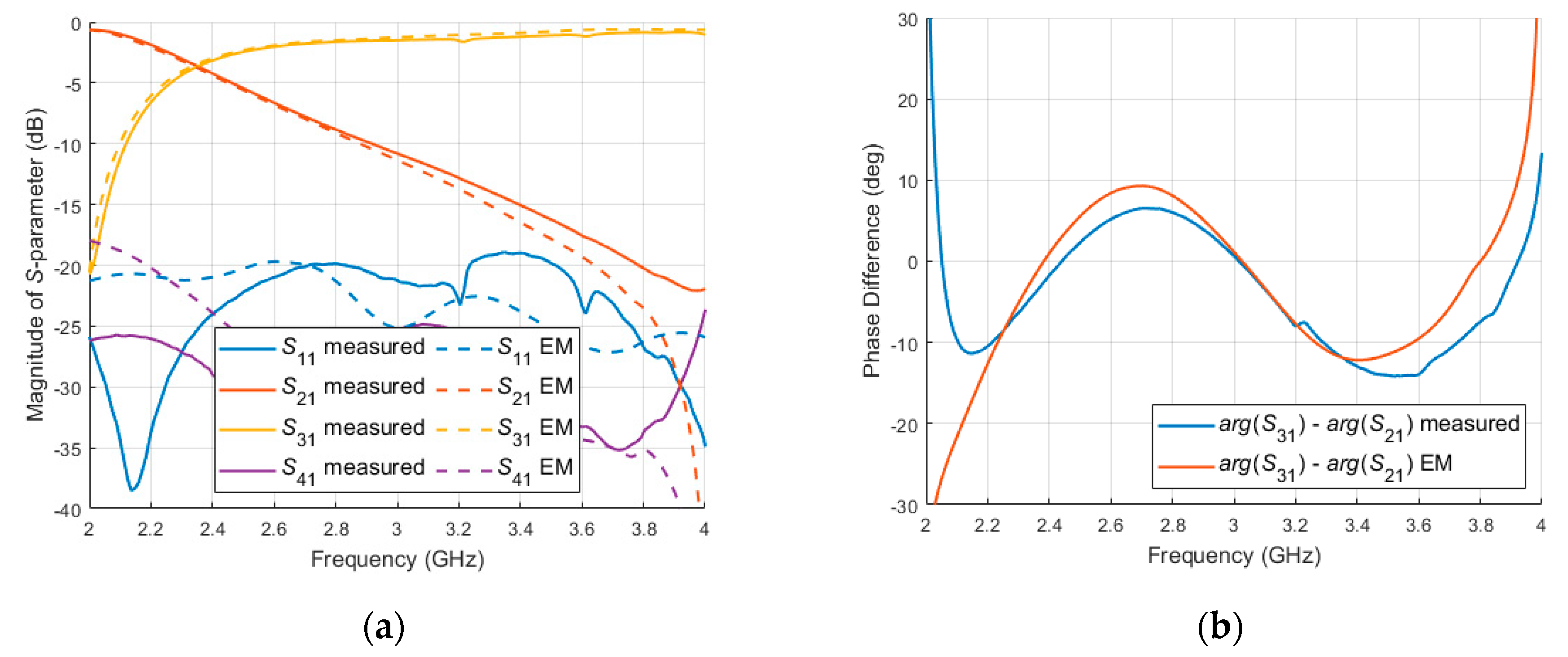
Figure 9. As can be seen, the appropriate switching function is achieved. Moreover, the directional filter features a good impedance match and differential phase variation not higher than ±10°. It is worth underlining that the larger phase imbalance is observed around the 2 GHz and 4 GHz frequencies. This has a negligible impact on the antenna array, since, in these regions, the magnitude difference for the LF and HF paths becomes large. Furthermore, the use of the filter provides almost constant gain across the one-frequency octave of the resulting antenna arrays. The performed simulation reveals that the gain change does not exceed ±1 dB for all beams of the eight-element array and 1L and 1R beams of the twelve-element antenna array and it does not exceed ±1.5 dB for 2L and 2R beams of the twelve-element array.
It has to be underlined that both proposed feeding networks allow good radiation properties of the resulting scalable antenna arrays to be achieved. Moreover, they are much simpler and easier to design than the solution described in [
23], where the concept of a four-beam antenna array operating in an octave frequency range is shown. This is due to the fact that broadband Butler matrices, power dividers and directional filters are well known, whereas the feeding network proposed in [
23] requires a very complicated modified Butler matrix, which consists of different types of directional couplers that change their properties over the bandwidth.
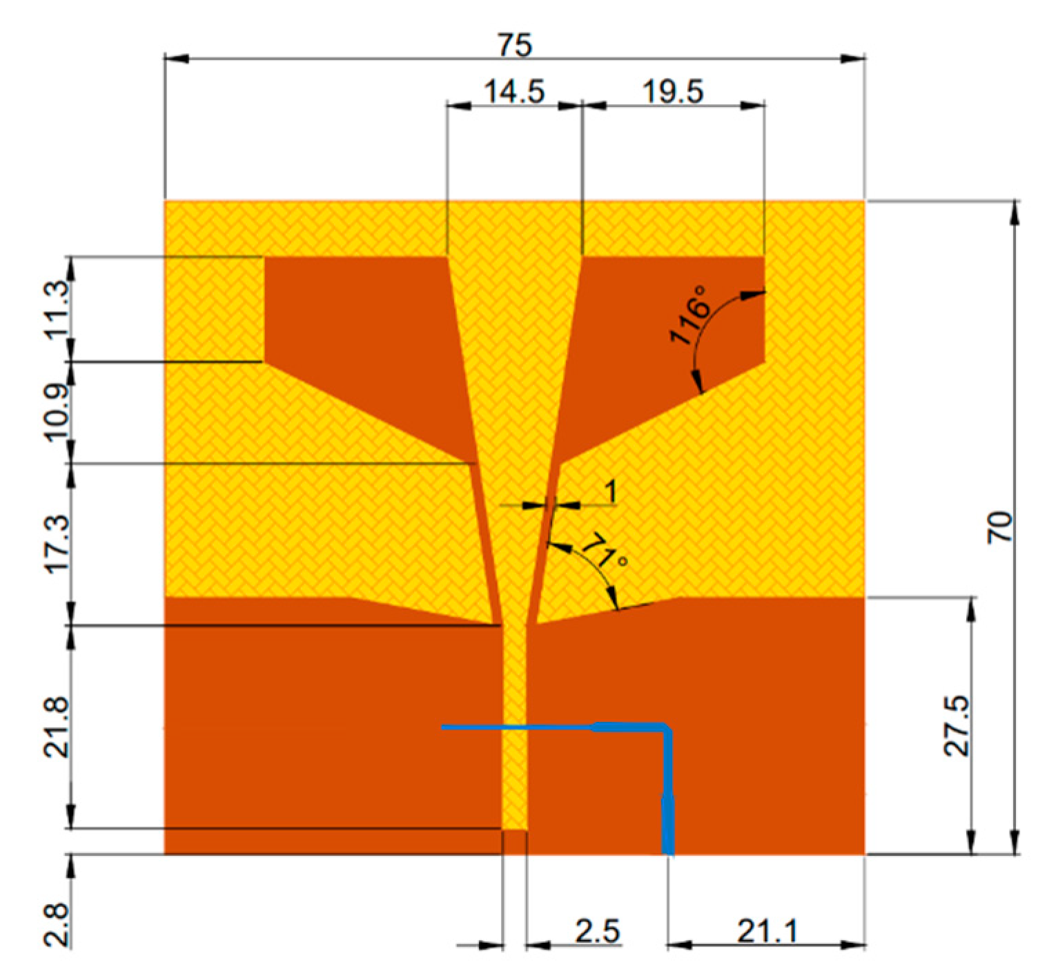
As a single radiation element, a linearly tapered slot antenna, shown in
Figure 10, was selected. Such a radiating element ensures very broad bandwidth, sufficient to cover one frequency octave on one hand and a stable radiation pattern over the bandwidth on the other hand [
26,
27,
28]. The linearly tapered slot antenna was optimized for operation in the 2–4 GHz frequency range. The obtained layout showing all the dimensions is presented in
Figure 10 and in
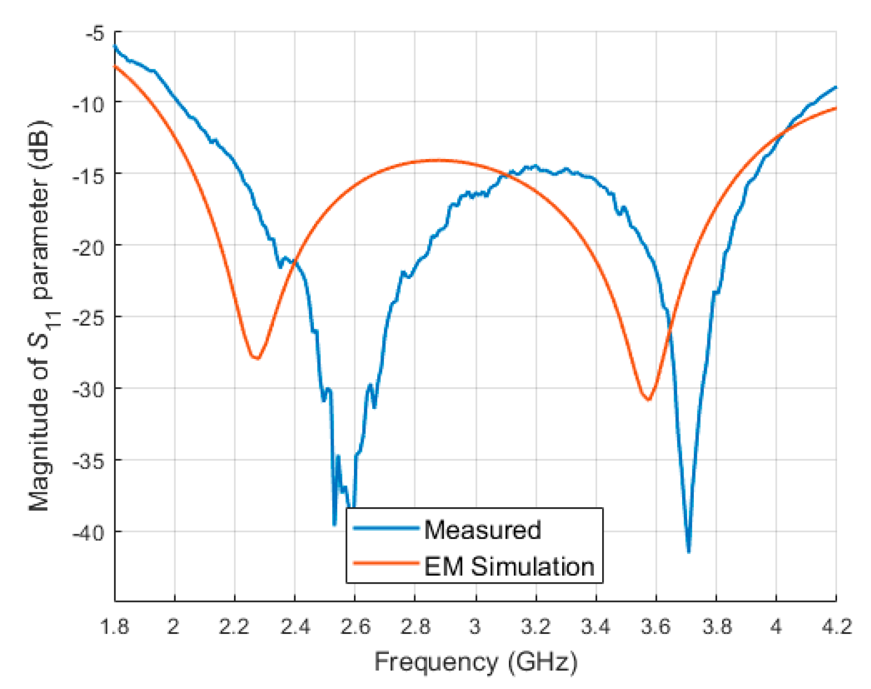
Table 2. The calculated reflection coefficient in comparison to the measured one is shown in
Figure 11 and is better than −10 dB within the required bandwidth. Although some discrepancies between the simulated and measured reflection coefficients are seen, most likely caused by the inaccuracy of the FR4 dielectric permittivity determination, the designed radiating element features good impedance match in the required bandwidth.
The radiating element was measured in an anechoic chamber. It was placed on the 3D-printed rail using plastic screws to avoid a negative impact on the radiation pattern. A reference horn antenna was placed on the other side of the anechoic chamber at a distance of 4 m. Both the reference antenna and the manufactured element were connected to the two-port vector network analyzer.
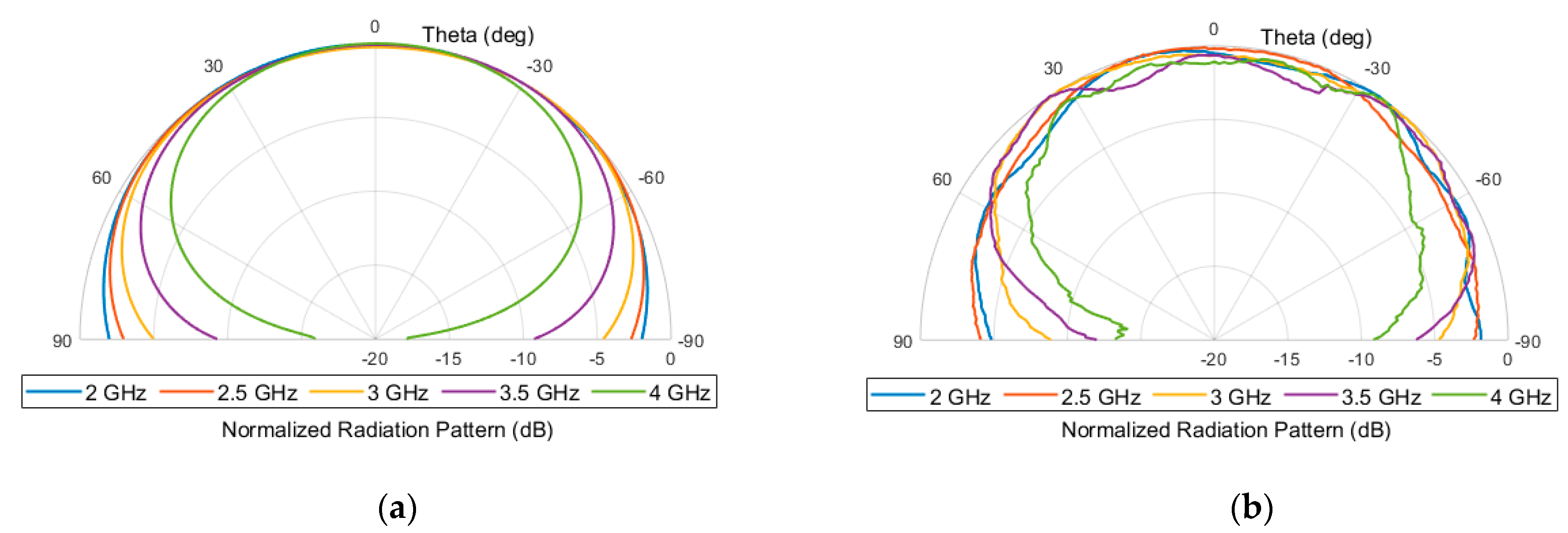
Figure 12 presents the calculated and measured radiation patterns of the developed linearly tapered slot antenna element and it is seen that the designed radiating element exhibits a wide beamwidth over the entire bandwidth, which is significant for applications in multi-beam antenna arrays.
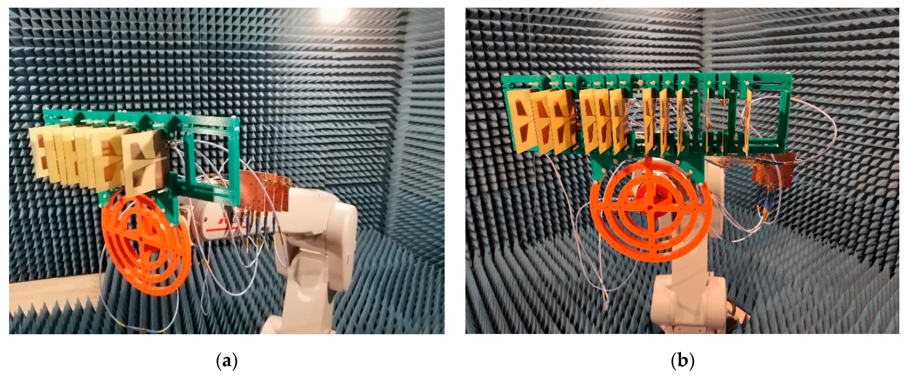
The developed radiating element was used in both concepts of scalable four-beam antenna arrays. The feeding network and the rail containing radiating elements were mounted on the back and front of the robotic arm, respectively. The feeding network was connected to the antenna array using SMA cables. Both reference antenna and antenna array were connected to the two-port vector network analyzer. As it is seen in
Figure 1 and
Figure 5, the feeding networks for both eight-element and twelve-element scalable antenna arrays have four ports so, for each of the ports, a separate measurement was conducted. During the measurements, one of the feeding network’s ports was connected to the network analyzer, whereas the other ports were terminated with 50 Ohm impedance.
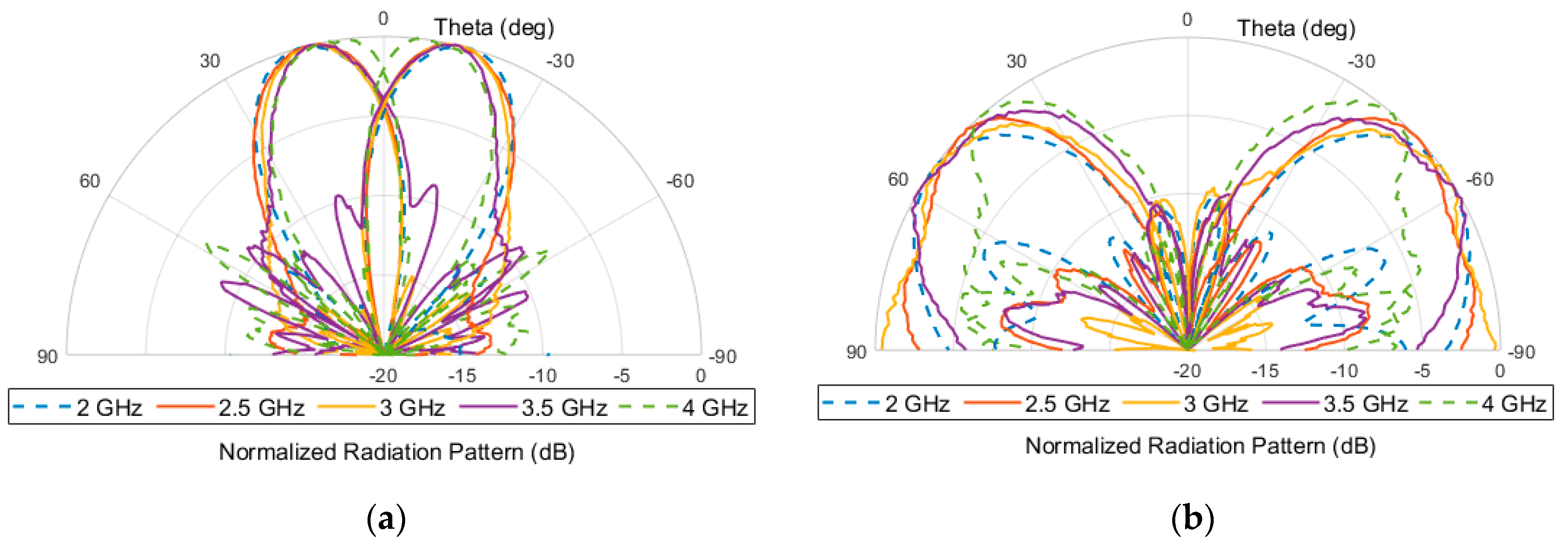
Figure 13 presents the radiation pattern of the eight-element antenna array in which additional attenuators and the radiation pattern of a single radiating element were taken into account. As can be seen, the application of such a radiating element slightly deteriorated the sidelobe level of the antenna array, but they were at an acceptable level since they did not exceed −8 dB. The developed radiating element and directional filter together with the previously developed broadband Butler matrix described in detail in [
19] were utilized to realize the broadband four-beam antenna array. The used Butler matrix exhibits bot return loss and isolation not worse than 20 dB and its transmission imbalance does not exceed ±1 dB/8° over the frequency of interest. Additionally, two 3 dB attenuators were added at the appropriate outputs of the Butler matrix. The assembled model of the four-beam antenna array was measured in an anechoic chamber. The obtained results are shown in
Figure 14. It can be seen that good radiation properties were achieved, i.e., the antenna array features constant beam directions and beamwidths. The achieved beamwidths’ variation does not exceed ±4° for 1L and 1R beams and ±6° for 2L and 2R beams, whereas the direction change does not exceed ±4° for 1L and 1R beams and ±2.5° for 2L and 2R beams, respectively.
Similarly, the concept of a scalable antenna array composed of twelve radiating elements was verified experimentally. The calculated radiation pattern in which the radiation pattern of the developed radiating element is taken into account is shown in
Figure 15. In addition, in this case, a good sidelobe level was achieved; however, a larger difference of the beamwidths caused by the directivity of the entire array is noticeable. The designed antenna array was developed based on the same components as in the case of eight-element antenna array. Additionally, in this case, two simple power dividers were developed to assemble the entire scalable antenna array. The obtained radiation pattern of the manufactured four-beam scalable antenna array is shown in
Figure 16. As can be seen, the achieved beamwidths’ variation does not exceed ±4° for 1L and 1R beams and ±18° for 2L and 2R beams, whereas the direction change does not exceed ±2.5° for 1L and 1R beams and ±7° for 2L and 2R beams, respectively.
To complete the description of the presented design, the radiation efficiency was calculated with the use of EM simulations. For the eight-element scalable antenna array, the radiation efficiency in the frequency range of interest varies from 81.3% to 76.4%. Similarly, for the twelve-element scalable antenna array, the radiation efficiency varies between 77.9% and 71.3%. Moreover, the measured radiation efficiencies for both antenna arrays possess similar behavior to the calculated ones. The measured radiation efficiency varies from 63.2% to 55.2% and from 54.6% to 47.4% for the eight-element array and the twelve-element array, respectively. The main cause for the disproportion between EM simulations and measurements is the EM simulation setup. During simulations, an ideal and lossless, apart from the 3 dB attenuators, feeding network was assumed. Such a condition cannot be met during measurements because it is well known that, theoretically, lossless circuits provide some attenuation in the signal path.
The obtained measurement results reveal some discrepancies between the calculated and measured radiation patterns of both the developed antenna arrays, caused by the couplings between radiating elements, which were not taken into account during the calculations, even though both the developed scalable multi-beam antenna arrays confirm the correctness of the proposed approach and prove the possibility of the realization of four-beam antenna arrays operating in an octave frequency range with the use of the proposed approach.
Figure 17 presents both the assembled models of the developed antenna arrays during measurements.
To illustrate the advantages of the presented solution against other recently reported multibeam antennas,
Table 3 is presented below. As can be seen, the considered designs offer a large variety in terms of number of beams and the frequency range of operation at the expense of the overall design complexity. It can be observed that the proposed design allows four beams with the lowest variation in terms of both direction and width to be obtained and, simultaneously, it features low complexity.


