
The Human—Unmanned Aerial Vehicle System Based on SSVEP—Brain Computer Interface


1
Department of Electronic Engineering, National Taipei University of Technology, Taipei City 10608, Taiwan
2
Department of Electronic Engineering, Lunghwa University of Science and Technology, Taoyuan City 333326, Taiwan
*
Author to whom correspondence should be addressed.
Electronics 2021, 10(23), 3025; https://0-doi-org.brum.beds.ac.uk/10.3390/electronics10233025
Submission received: 22 October 2021
/
Revised: 25 November 2021
/
Accepted: 29 November 2021
/
Published: 3 December 2021
(This article belongs to the Special Issue Advanced Technologies and Challenges in Brain Machine Interface)
Abstract
:The brain–computer interface (BCI) is a mechanism for extracting information from the brain, with this information used for various applications. This study proposes a method to control an unmanned aerial vehicle (UAV) flying through a BCI system using the steady-state visual evoked potential (SSVEP) approach. The UAV’s screen emits three frequencies for visual stimulation: 15, 23, and 31 Hz for the UAV’s left-turn, forward-flight, and right-turn functions. Due to the requirement of immediate response to the UAV flight, this paper proposes a method to improve the accuracy rate and reduce the time required to correct instruction errors in the resolution of brainwave signals received by UAVs. This study tested ten subjects and verified that the proposed method has a 10% improvement inaccuracy. While the traditional method can take 8 s to correct an error, the proposed method requires only 1 s, making it more suitable for practical applications in UAVs. Furthermore, such a BCI application for UAV systems can achieve the same experience of using the remote control for physically challenged patients.
1. Introduction
A brain–computer interface (BCI) [1,2,3,4] is a medium for communicating between the human brain and peripheral devices. Through BCI, signals generated in the brain can be used to control and operate peripheral devices, i.e., to translate physical signals from the human body into machine commands that we specify to control the peripheral devices. BCI has been highly discussed in medical engineering, where this technology allows people to control devices independently of the neuromuscular functions of the human body and communicate with each other to transmit messages between humans and machines [4,5,6,7,8,9]. The implementation of BCI relies on an electroencephalogram (EEG). EEG [10,11,12,13] is a non-invasive BCI that uses electrical conductors and records brain activity without any medical or surgical involvement. The electrical activity of the brain is recorded and detected by using electrodes attached to the scalp. Therefore, BCI is a potential solution for those patients who still have normal brain function but are physically disabled or paralyzed, making them unable to communicate with the external environment through their severely damaged muscles and nervous system.
In medical and medical engineering research, EEG is widely used to detect changes in brain activity to diagnose brain diseases. For example, EEG can be used to identify brain death in people who are in a persistent coma. In addition, serial EEGs have been used to help find the appropriate level of anesthesia for people in medically induced comas. Thus, EEG is used to detect changes in brain activity. EEG is also helpful in the diagnosis or treatment of diseases such as brain damage from a head injury, cerebral palsy [14], amyotrophic lateral sclerosis (ALS) [15], spinal muscular atrophy (SMA), and Parkinson’s disease [16]. Patients with these severe movement disorders are unable to communicate with the external environment [17]. Another application of BCI technology is to help people with problems in muscle movement and control. Therefore, many experts have started to think about the application of BCI to these patients, allowing them to control external devices or express their intentions without relying on the surrounding neuromuscular functions. Through specific brain signals elicited by the designed task, the measured brain signals are translated into communication or control signals to help the patient communicate with the external environment.
Several popular BCI modalities can use brain signals to control machines, such as motion imagery [18,19,20,21], P300 waves [22,23], flash visual evoked potential (FVEP) [24,25], and steady-state visual evoked potential (SSVEP) [26,27,28,29,30,31]. Among them, FVEP and SSVEP are the most common BCIs based on EEG. The SSVEP method is also widely used because of its high signal-to-noise ratio and robustness advantages. SSVEP sensing refers to the uninterrupted response in the human brain’s visual cortex related to the frequency of the stimulus when the brain is stimulated with a fixed-frequency flicker block. Using SSVEP to generate responses in the brain is a very useful natural involuntary phenomenon that has been tested many times by researchers. Regan designed the earliest SSVEP–BCI system in 1979, where subjects could select a blinking button on a computer screen by simply looking at it, essentially achieving the desired design goal. In this paper, we chose SSVEP because it does not require any training phase for the subject and has very high accuracy.
Connecting the brain with machines or robots has long been a goal of humans. One such application is the use of the brain to control unmanned aerial vehicles (UAV) [32,33,34]. While UAVs have been used in various fields, a UAV needs to be controlled by a skilled person. Therefore, it is difficult for people who have not been in contact with UAVs to operate them, including physically disabled people and particularly those with hand impairments. Therefore, the function of using the brain to connect and operate a UAV by using brain signals has become very topical. In this paper, a new intelligent UAV—only needing to be controlled by brainwaves and not through muscles—is designed. It also allows people with physical disabilities to control the UAV flight. Non-invasive EEG-based BCI is the most prospective interface in the application space for people with severe motor disabilities because of its non-invasiveness, low cost, practicality, portability, and ease of use. The eye is stimulated by the steady-state visual evoked potential (SSVEP) signal, generating response fluctuations in the brain that are extracted from brain fluctuations by EEG to the microcontroller. The microcontroller is then transmitted to the wireless signal receiver of the UAV through the transmitter of the wireless module. The UAV’s controller then parses the signals through a wireless signal receiver to realize the functions of controlling the UAV’s forward, left, and right flight.
It is possible that the UAV may be unable to make an immediate judgment. For example, if the UAV is inputted to turn left but it takes 10 s for it to react to the left turn, it is possible that during these 10 s the UAV is already in crisis, such as hitting a tree, and such a system will not be able to make practical applications. Therefore, it is an essential task of the UAV to react in the quickest possible time. If we want to use a brainwave to control the UAV’s function, it is necessary to overcome the real-time operation. In this paper, we propose a practical method using ten people to shorten the analysis time and obtain a greater performance, especially in terms of immediacy and accuracy.
This paper is organized as follows: In Section 2, the experimental paradigm and analysis methods of brain signals and the motion model of UAV are presented. In Section 3, a summary and discussion are given. Furthermore, a comparison of the old and new methods’ accuracy of experiments is made. Our experiments validate our ideas and achieve the expected results. Finally, conclusions and the prospects for future applications are given in Section 4.
2. Materials and Methods
Ten healthy subjects (seven males and three females, aged 22–32) were invited to participate in this experiment. The aim was to perform some UAV control tasks by generating messages in the brain after visual stimulation of the subject’s eyes. All participants had no history of visual disease and each had corrected Snellen vision of 6/6 or better. In addition, all participants had a clear understanding of the experiment and signed a consent form before participation.
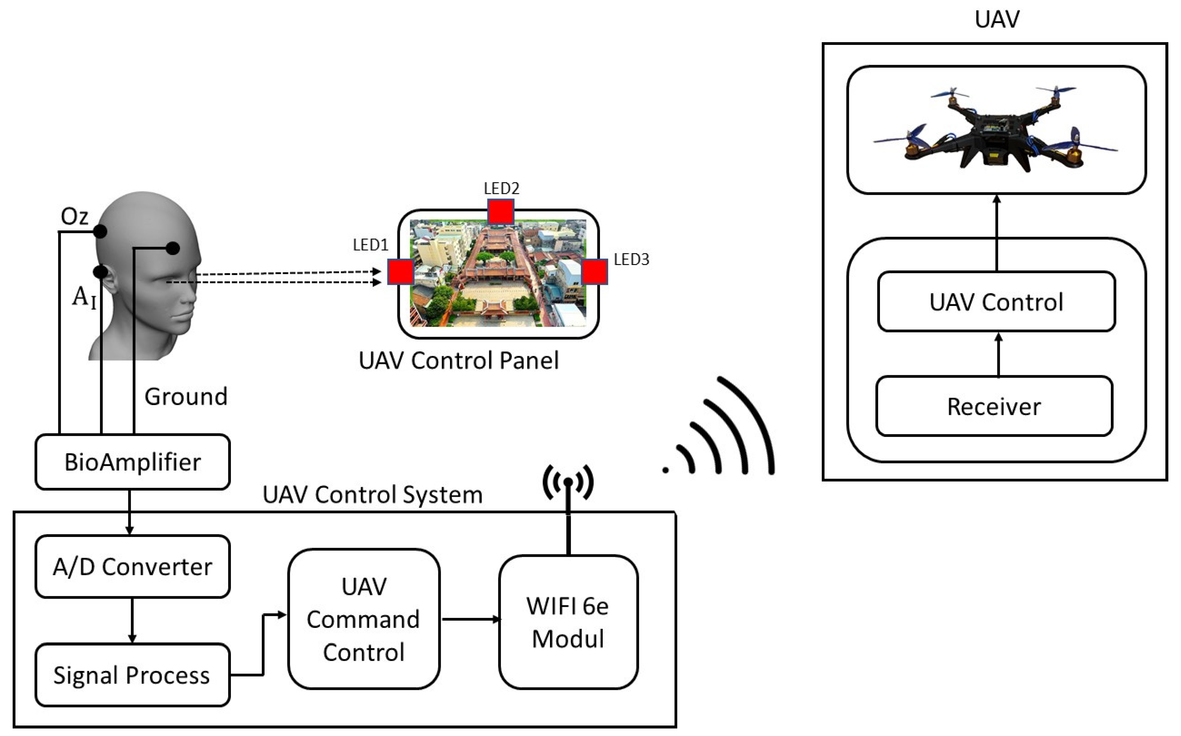
The experiment was conducted using a 6 cm × 6 cm panel as a visual stimulus with light-emitting diodes (LEDs) produced by CREE, USA on UAV panel, placed on the left, right, and above the panel, respectively, designated to stimulate SSVEP. Stimulus frequency was selected as 15 Hz, 23 Hz, and 31 Hz. The 15 Hz LED is located on the left side of the panel and the 23 Hz LED on the right side, with the 31 Hz LED located on the top of the panel. A frequency of 15 Hz means that the UAV is controlled to bend to the left and a frequency of 23 Hz means that it is controlled to bend to the right. Moreover, a frequency of 31 Hz means that the UAV is controlled to fly forward.
In this study, all EEG electrode placements were based with 32 pathway electrode positions of 10–20 international system and PowerLAB system with 1 kHz sampling rate and collection of brainwave signals in the 10–50 Hz band. Subjects were seated in comfortable chairs and tested separately, using an LED light source located in front of them and a designated optical source 40 cm away from the subject’s eyes. We used Oz and Fp2 electrode locations to obtain SSVEP data of the brain.
Figure 1 shows the overall architecture. The hardware system for this experiment consists of five main components: the EEG signal acquisition system, the visual stimulation panel, the signal processing computer, the Wi-Fi 6E wireless transmission signal module, and the unmanned aerial vehicle. The SSVEPs caused by the flashing of three LEDs on the visual stimulation panel were used to control three functions of the UAV. When the subject looked at the screen’s left, right, and top LEDs, each had corresponding frequencies for visual stimulation. For example, when looking at the left LED, it will send out a 15 Hz signal to stimulate the subject’s eyes, and the brain will respond by generating a 15 Hz brainwave signal. This signal was extracted through the EEG and transmitted to the UAV control system via the BioAmp brainwave amplifier and A/D converter. The UAV control system was then transmitted to the UAV via wireless communication. The article in [35] mentions Wi-Fi networks using the IEEE 802.11n and 802.11ac standards to communicate with the UAV. The wireless communication system used in this article was the Wi-Fi 6E protocol, an extension of Wi-Fi 6, developed by the Wi-Fi Alliance in January 2020. Wi-Fi 6E adds a 6G band, which has the advantage of a wider bandwidth and reduced congestion. When the UAV receives the signal, the central processing controller will perform a fast Fourier transform (FFT) to resolve the 15 Hz signal, corresponding to a left turn. Similarly, the UAV receives 23 Hz to fly to the right and 31 Hz to fly forward.
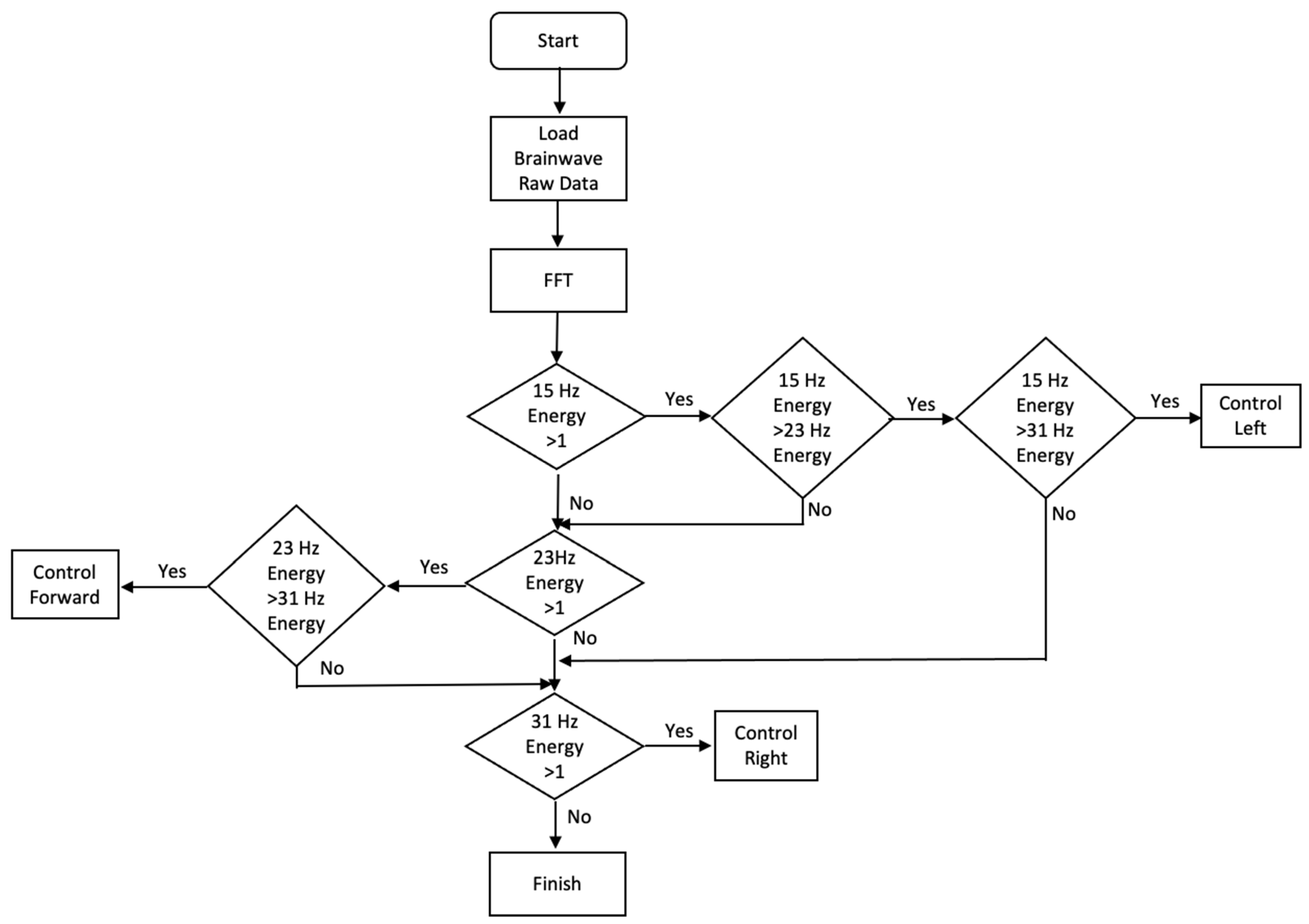
Figure 2 shows the software architecture of the UAV. When the UAV receives data from the wireless receiver, it parses the data using FFT and then identifies the energy at 15, 23, or 31 Hz. When the 15 Hz peak is found to be the highest, the UAV is given a left turn. If the peak at 23 Hz is the highest, then the UAV will fly forward. If the 31 Hz peak is the highest, the UAV is controlled to make a right turn. If the energy of all three frequencies does not exceed 1, then no action is taken.
According to [36], the subjects were asked to look at LEDs with 15, 23, and 31 Hz frequencies for 20 s. The brain generated brainwave signals at 15, 23, and 31 Hz, respectively; therefore, the UAV received 15, 23, and 31 Hz brainwave signals. The SSVEP frequency was analyzed by parsing the raw data of these three frequencies every 4 s. Because the data was intercepted every 4 s, the 20 s were divided into five segments. In other words, the 20-s 15 Hz signal received by the UAV was divided into five segments, all of which were theoretically 15 Hz signals.
Similarly, the 20-s 23 Hz signal received by the UAV also had five 23 Hz signals. Likewise, if the UAV received a 31 Hz signal for 20 s, there would be five 31 Hz signals. Nevertheless, there will be noise in the actual operation, so it is not necessarily that these five are all 15 Hz, 23 Hz, or 31 Hz. We will perform a statistical analysis and calculate the accuracy of the actual operation from the result of each frequency.
In the traditional method, for every 4 s of EEG data, the subsequent EEG data must wait for the next full 4 s. If the parsed result is wrong, the earliest it can be corrected is another 4 s, taking the correction time to 8 s. The 8-s response time for the UAV is too long and lacks immediacy. Therefore, this study proposes an improved method. The base of EEG data every 4 s remains the same, but the acquisition method is modified. In other words, the conventional method is 0–4 s for the first EEG data, 4–8 s for the second EEG data, 8–12 s for the third EEG data, etc. The optimized method keeps the first EEG data for 0–4 s, but changes the second EEG data to intercept EEG data for 1–5 s, the third EEG data for 2–6 s, etc. From the second time onwards, only 1 s is added as the new EEG data. This has the advantage of correcting an error in as little as 1 s, representing a significant improvement on the traditional method and more in line with the real-time nature of UAVs.
3. Results
This section discusses the accuracy of the signal restoration using both the traditional and optimized methods of parsing EEG data. Both methods analyze the UAVs to determine whether the information is still recovered as an actual signal under visual stimuli at 15 Hz, 23 Hz, and 31 Hz, respectively. The accuracy of the two analysis methods is compared for 15 Hz, 23 Hz, and 31 Hz frequencies.
3.1. 15 Hz
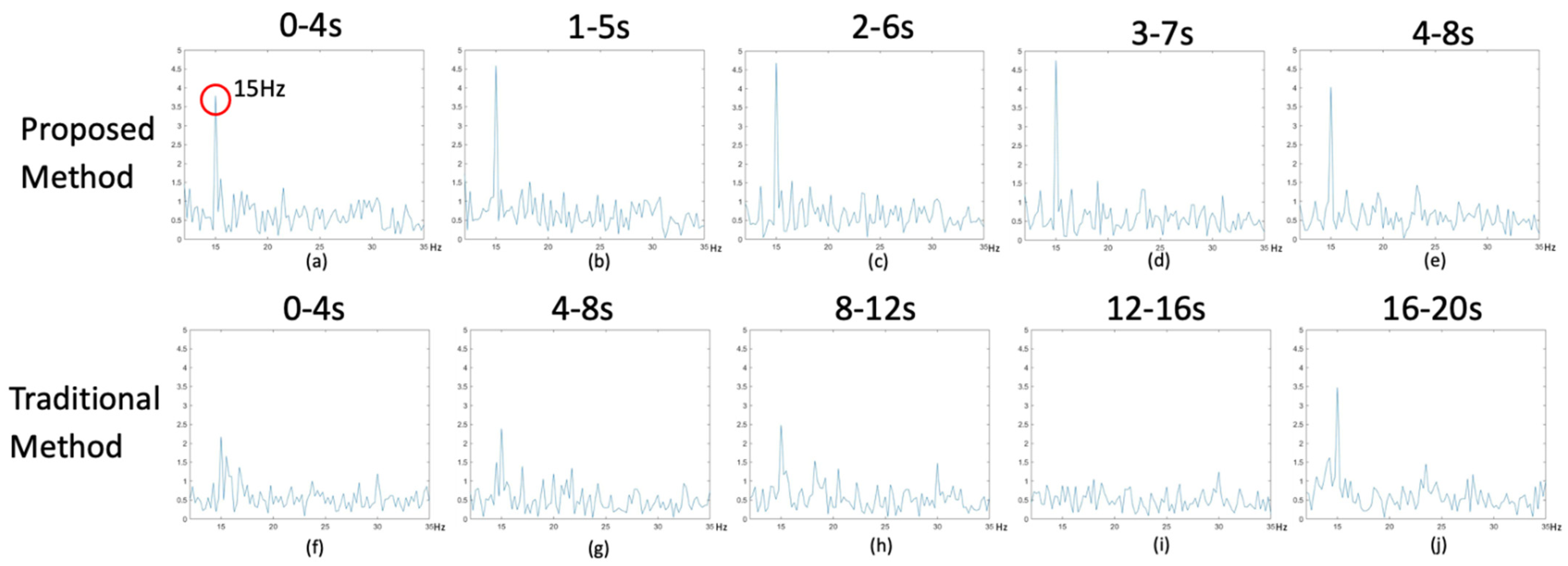
Figure 3 analyzes the 15 Hz EEG signal. Figure 3a–e shows the optimized method for analyzing EEG data, while Figure 3f–j shows the traditional method. When the subject looks at the LED at 15 Hz, it can be seen from the spectrum observation that 15 Hz has a higher peak value than other frequencies, as shown in Figure 3a. Therefore, the proposed method can restore the 15 Hz signal in five segments. In the conventional method, four bands can be restored to 15 Hz, but one of them is misjudged and the signal strength of five segments is weak. A comparison shows that the new method takes only 8 s to obtain the five 15 Hz data, but the old method takes 20 s. Thus, the new method shortens the time and improves the accuracy.
3.2. 23 Hz
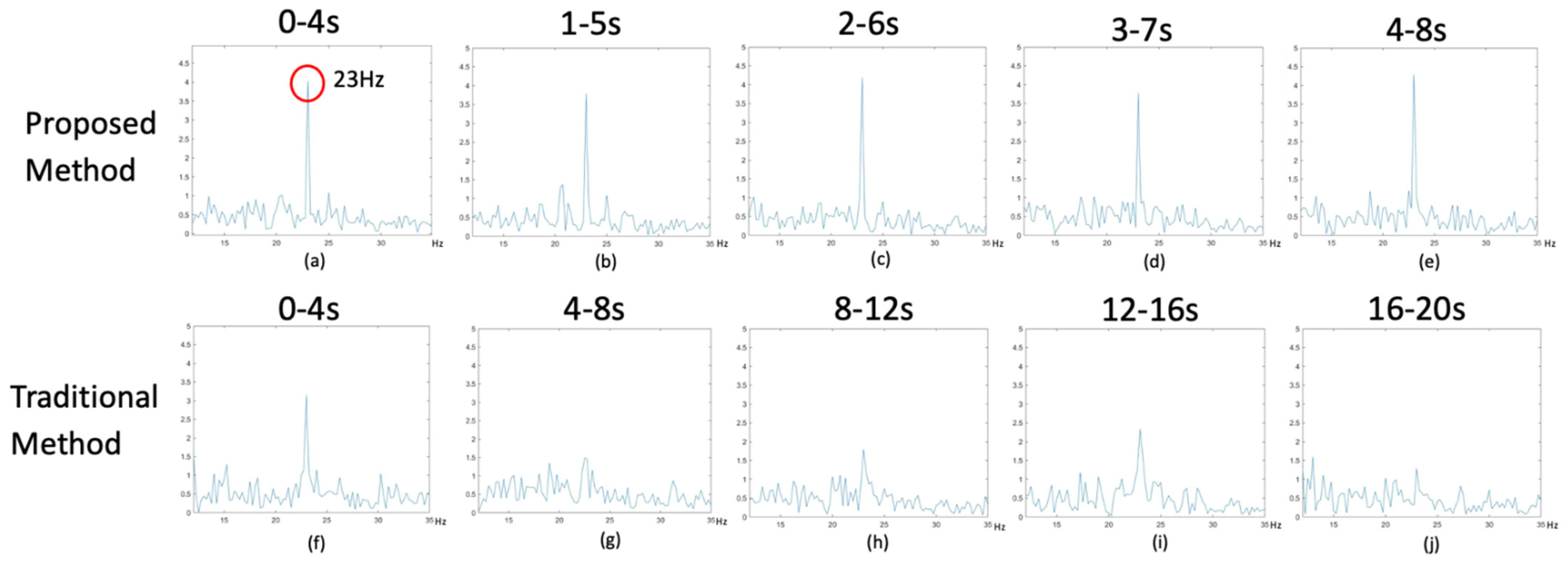
Figure 4 analyzes the 23 Hz EEG signal. Figure 4a–e shows the optimized method for analyzing EEG data, while Figure 4f–j shows the traditional method. While the subject is looking at the LED at 23 Hz, the spectrum observation shows that 23 Hz has a higher peak value than other frequencies, as shown in Figure 4a. Therefore, the proposed method can restore the 23 Hz signal in all five segments. In the conventional method, four segments can be restored to 23 Hz, but one of them is incorrectly determined, and all five segments have weaker signal strength. A comparison shows that the new method takes only 8 s to obtain five 23 Hz data, but the old method takes 20 s. Thus, the new method shortens the time and improves the accuracy.
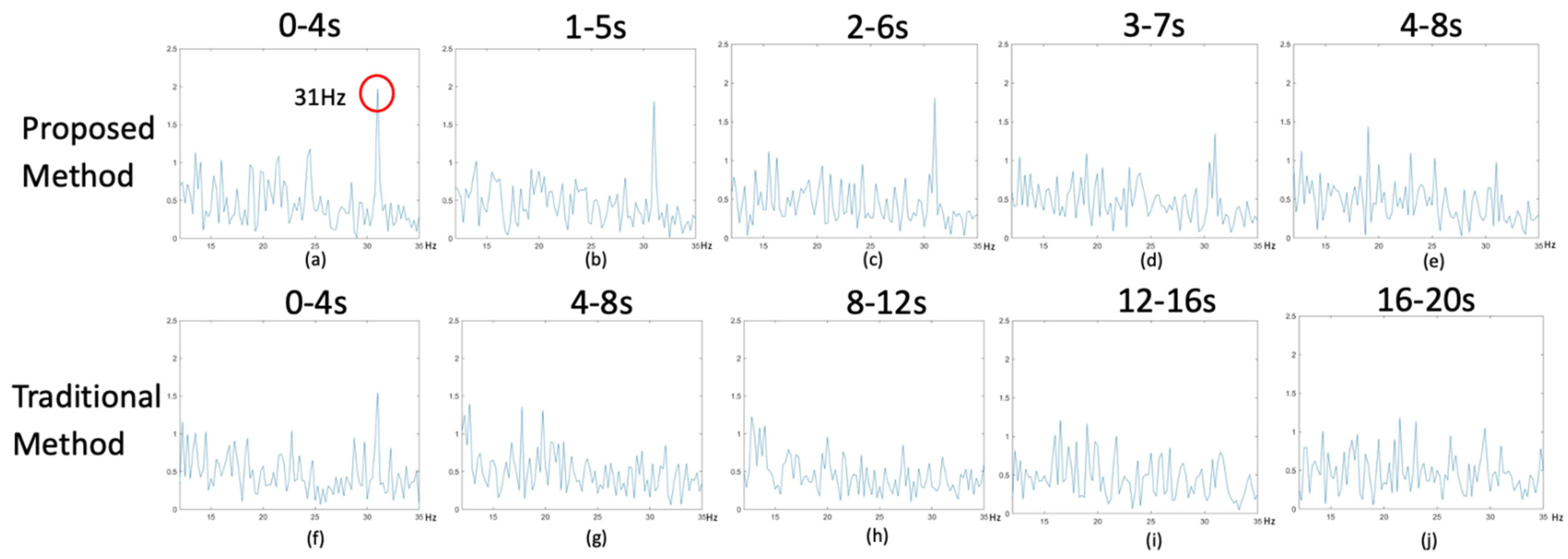
3.3. 31 Hz
Figure 5 analyzes the 31 Hz EEG signal. Figure 5a–e shows the optimized method for analyzing EEG data, while Figure 5f–j shows the traditional method. While the subject is looking at the LED at 31 Hz, the spectrum observation shows that 31 Hz has a higher peak value than other frequencies, as shown in Figure 5a. Therefore, in the proposed method, five segments can recover the 31 Hz signal but one of them will be judged incorrectly. On the other hand, in the traditional method, one band can recover the 31 Hz signal but four of them will be misjudged, and all five segments have a lower signal strength. A comparison shows that the new method takes only 8 s to obtain five segments of 31 Hz data, but the old method takes 20 s. Thus, the new method shortens the time and improves the accuracy.
3.4. Comparison
Table 1 and Table 2 represent the results of signal analysis at 15 Hz using the proposed method and the traditional method. The results of using the proposed method and the traditional method at 23 Hz are shown in Table 3 and Table 4. In Table 5 and Table 6, the results are the results of resolving the signal at 31 Hz by the proposed method and the traditional method, respectively. The subject IDs are A–E. The success of each person’s brainwave-controlled UAV in executing the correct command was recorded separately. “On” means success and “off” means failure.
In Table 1, 15 Hz was successfully resolved in all five time intervals for subjects A–E. However, in Table 2, 15 Hz was not resolved correctly in one time segment for subjects B and C. In Table 3, 23 Hz was successfully parsed in all five time slots for subjects A–E. However, in Table 4, 23 Hz was not resolved correctly in one time interval for subjects B and D. In Table 5 and Table 6, the success rate of 31 Hz in the five time intervals of subjects A–E was much lower than either the proposed method or the conventional method.
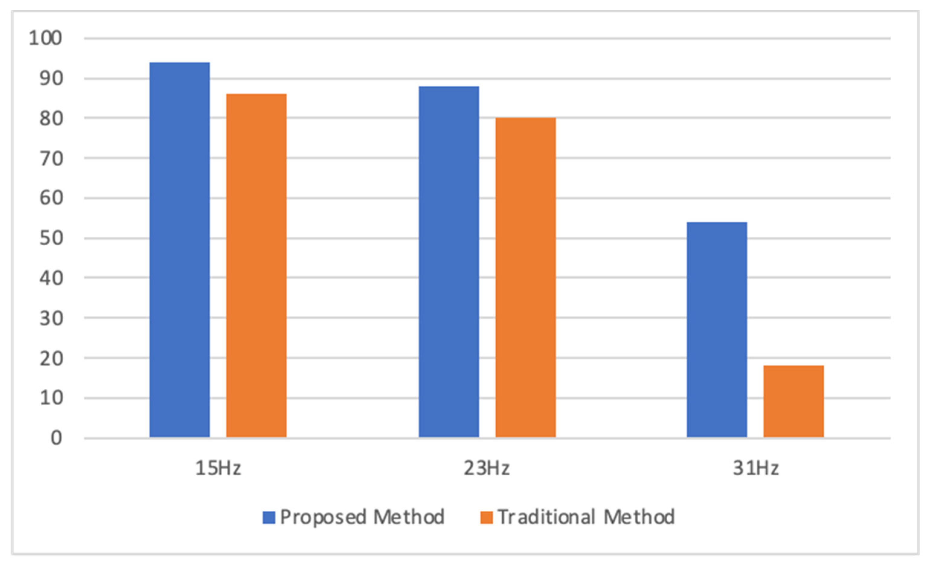
Table 7 shows the accuracy comparison between the traditional and optimized methods of resolving EEG data. From Table 7, it is clear that the proposed method is better than the traditional method by 8% in 15 Hz. In 23 Hz, the proposed method is better than the traditional method by 8%, while at 31 Hz, the proposed method is better than the traditional method by 36%. Therefore, the accuracy of the proposed method is 85.3% when the traditional method and the proposed method are summed at 15 Hz, 23 Hz, and 31 Hz. The accuracy of the proposed method is 68% when the conventional method is summed at 15 Hz, 23 Hz, and 31 Hz. Therefore, the proposed method represents a 17.3% improvement. Figure 6 provides a graphical comparison of the accuracy rates of the proposed method versus the traditional method.
4. Conclusions
This study proposes a BCI system based on the SSVEP approach to control the behavior of UAVs. By using visual stimulation, the eyes will look at different frequencies and the brain will make different responses according to the different frequencies. The BCI system was used to extract the response from the brain stimulation to the UAV, with the UAV performing the corresponding function according to these signals. In this experiment, three LED frequencies were used: 15 Hz, 23 Hz, and 31 Hz. When the 15 Hz LED is focused on, the UAV will fly to the left; when the 31 Hz LED is focused, the UAV will fly forward; when the 23 Hz LED is focused, the UAV will fly to the right.
For UAVs, the controls must be immediately reactive. The ability to control the UAV in real-time makes it worthwhile. When using a brainwave to generate the input signal of a UAV, the traditional method of parsing brainwave signals is to capture the signal every 4 s and wait 4 s for the next signal. This means that each command takes 4 s. As shown in Section 3, it takes 20 s to analyze the signal five times, which is very time-consuming. The method proposed in this paper aims to solve this issue. It also intercepts the signal in 4 s, but the difference is in the intercepted segment. The first signal interception is 0–4 s, the second is 1–5 s, the third is 2–6 s, etc. Therefore, the first signal takes 4 s to intercept, but it only needs to wait 1 s to form a 4-s signal from the second signal.
The proposed method has two advantages. First, it can significantly reduce the time required to obtain commands. Instead of waiting 4 s to obtain a UAV command, the proposed method can generate one in only 1 s. Because of the shortened time, it is possible to react more quickly to correct errors when they occur. In other words, when an error occurs, the traditional method can take as little as 4 s to correct the error but the proposed method takes only 1 s to do so, making the use of brainwaves to control the UAV more responsive to real-time needs. Second, the accuracy rate is used to compare the traditional method with the proposed method. The proposed method increases 8% over the traditional method at 15 Hz, by 8% at 23 Hz, and by 36% at 31 Hz. Combining the accuracy of 15 Hz, 23 Hz, and 31 Hz, the proposed method increases 17.34% over the conventional method while also improving the accuracy.
In conclusion, we have designed the SSVEP–BCI Human–Unmanned Aerial Vehicle system and propose a new method that can shorten the analysis time and obtain excellent performance, especially immediacy and accuracy. In the future, this SSVEP–BCI control technology and new method can be accurately applied to different fields, including hospital beds, wheelchairs, home environments, and humanoid robots, making system control that does not require muscle operation more straightforward and more effortless.
Author Contributions
Conceptualization, M.-A.C., C.-W.L. and C.-T.C.; methodology, M.-A.C. and C.-W.L.; software, M.-A.C. and C.-W.L.; validation, M.-A.C., C.-W.L. and C.-T.C.; formal analysis, M.-A.C., C.-W.L. and C.-T.C.; investigation, M.-A.C., C.-W.L. and C.-T.C.; resources, M.-A.C., C.-W.L. and C.-T.C.; writing—original draft preparation, M.-A.C. and C.-W.L.; writing—review and editing, M.-A.C.; visualization, M.-A.C.; supervision, M.-A.C.; project administration, M.-A.C.; funding acquisition, M.-A.C. All authors have read and agreed to the published version of the manuscript.
Funding
This work was supported by the Ministry of Science and Technology, Taiwan, R.O.C under Grant Project MOST 109-2222-E-027-008.
Data Availability Statement
All data are included within manuscript.
Conflicts of Interest
The authors declare no conflict of interest.
References
- Wolpaw, J.R.; Birbaumer, N.; McFarland, D.J.; Pfurtscheller, G.; Vaughan, T.M. Brain–computer interfaces for communication and control. Clin. Neurophysiol. 2002, 113, 767–791. [Google Scholar] [CrossRef]
- Mridha, M.F.; Das, S.C.; Kabir, M.M.; Lima, A.A.; Islam, R.; Watanobe, Y. Brain-Computer Interface: Advancement and Challenges. Sensors 2021, 21, 5746. [Google Scholar] [CrossRef]
- Choi, H.; Lim, H.; Kim, J.W.; Kang, Y.J.; Ku, J. Brain Computer Interface-Based Action Observation Game Enhances Mu Suppression in Patients with Stroke. Electronics 2019, 8, 1466. [Google Scholar] [CrossRef] [Green Version]
- Bonci, A.; Fiori, S.; Higashi, H.; Tanaka, T.; Verdini, F. An Introductory Tutorial on Brain–Computer Interfaces and Their Applications. Electronics 2021, 10, 560. [Google Scholar] [CrossRef]
- Palumbo, A.; Gramigna, V.; Calabrese, B.; Ielpo, N. Motor-Imagery EEG-Based BCIs in Wheelchair Movement and Control: A Systematic Literature Review. Sensors 2021, 21, 6285. [Google Scholar] [CrossRef] [PubMed]
- Ko, L.W.; Chikara, R.K.; Lee, Y.C.; Lin, W.C. Exploration of user’s mental state changes during performing brain–computer interface. Sensors 2020, 20, 3169. [Google Scholar] [CrossRef] [PubMed]
- Flesher, S.N.; Downey, J.E.; Weiss, J.M.; Hughes, C.L.; Herrera, A.J.; Tyler-Kabara, E.C.; Boninger, M.L.; Collinger, J.L.; Gaunt, R.A. A brain-computer interface that evokes tactile sensations improves robotic arm control. Science 2021, 372, 831–836. [Google Scholar] [CrossRef]
- Liu, M.; Wang, K.; Chen, X.; Zhao, J.; Chen, Y.; Wang, H.; Wang, J.; Xu, S. Indoor Simulated Training Environment for Brain-Controlled Wheelchair Based on Steady-State Visual Evoked Potentials. Front. Neurorobotics 2020, 13, 101. [Google Scholar] [CrossRef]
- Lu, R.-R.; Zheng, M.-X.; Li, J.; Gao, T.-H.; Hua, X.-Y.; Liu, G.; Huang, S.-H.; Xu, J.-G.; Wu, Y. Motor imagery based brain-computer interface control of continuous passive motion for wrist extension recovery in chronic stroke patients. Neurosci. Lett. 2020, 718, 134727. [Google Scholar] [CrossRef] [PubMed]
- Mason, S.G.; Bashashati, A.; Fatourechi, M.; Navarro, K.F.; Birch, G.E. A Comprehensive Survey of Brain Interface Technology Designs. Ann. Biomed. Eng. 2006, 35, 137–169. [Google Scholar] [CrossRef] [PubMed]
- Hochberg, L.R.; Donoghue, J.P. Sensors for brain-computer interfaces. IEEE Eng. Med. Boil. Mag. 2006, 25, 32–38. [Google Scholar] [CrossRef] [PubMed]
- Korovesis, N.; Kandris, D.; Koulouras, G.; Alexandridis, A. Robot Motion Control via an EEG-Based Brain–Computer Interface by Using Neural Networks and Alpha Brainwaves. Electronics 2019, 8, 1387. [Google Scholar] [CrossRef] [Green Version]
- Kim, M.; Kim, M.-K.; Hwang, M.; Kim, H.-Y.; Cho, J.; Kim, S.-P. Online Home Appliance Control Using EEG-Based Brain–Computer Interfaces. Electronics 2019, 8, 1101. [Google Scholar] [CrossRef] [Green Version]
- Shushtarian, S.M.M.; Tajik, F.; Abdolhoseinpour, H. Measurement of Visual Evoked Potentials in Patients with Spastic Cerebral Palsy. J. Ophthalmic Optom. Sci. 2018, 2, 10–13. [Google Scholar]
- Verbaarschot, C.; Tump, D.; Lutu, A.; Borhanazad, M.; Thielen, J.; Broek, P.V.D.; Farquhar, J.; Weikamp, J.; Raaphorst, J.; Groothuis, J.T.; et al. A visual brain-computer interface as communication aid for patients with amyotrophic lateral sclerosis. Clin. Neurophysiol. 2021, 132, 2404–2415. [Google Scholar] [CrossRef]
- He, S.-B.; Liu, C.-Y.; Chen, L.-D.; Ye, Z.-N.; Zhang, Y.-P.; Tang, W.-G.; Wang, B.-D.; Gao, X. Meta-Analysis of Visual Evoked Potential and Parkinson’s Disease. Park. Dis. 2018, 2018, 1–8. [Google Scholar] [CrossRef]
- Pojda-Wilczek, D. Visual-evoked potentials in patients with brain circulatory problems. Int. J. Neurosci. 2014, 125, 264–269. [Google Scholar] [CrossRef]
- Kwon, M.; Cho, H.; Won, K.; Ahn, M.; Jun, S.C. Use of Both Eyes-Open and Eyes-Closed Resting States May Yield a More Robust Predictor of Motor Imagery BCI Performance. Electronics 2020, 9, 690. [Google Scholar] [CrossRef]
- Ren, S.; Wang, W.; Hou, Z.-G.; Liang, X.; Wang, J.; Shi, W. Enhanced Motor Imagery Based Brain- Computer Interface via FES and VR for Lower Limbs. IEEE Trans. Neural Syst. Rehabil. Eng. 2020, 28, 1846–1855. [Google Scholar] [CrossRef]
- Xu, F.; Rong, F.; Miao, Y.; Sun, Y.; Dong, G.; Li, H.; Li, J.; Wang, Y.; Leng, J. Representation Learning for Motor Imagery Recognition with Deep Neural Network. Electronics 2021, 10, 112. [Google Scholar] [CrossRef]
- Miah, A.S.M.; Rahim, A.; Shin, J. Motor-imagery classification using riemannian geometry with median absolute deviation. Electronics 2020, 9, 1584. [Google Scholar] [CrossRef]
- Chen, Z.; Jin, J.; Daly, I.; Zuo, C.; Wang, X.; Cichocki, A. Effects of Visual Attention on Tactile P300 BCI. Comput. Intell. Neurosci. 2020, 2020, 1–11. [Google Scholar] [CrossRef] [PubMed] [Green Version]
- Kim, S.; Lee, S.; Kang, H.; Kim, S.; Ahn, M. P300 Brain–Computer Interface-Based Drone Control in Virtual and Augmented Reality. Sensors 2021, 21, 5765. [Google Scholar] [CrossRef]
- Arruda, J.E.; McInnis, M.C.; Steele, J. The flash visual evoked potential-P2 and the detection of amnestic mild cognitive impairment: A review of empirical literature. Int. J. Psychophysiol. 2020, 155, 162–167. [Google Scholar] [CrossRef] [PubMed]
- Ström, L.; Bröjer, J.; Ekesten, B. Variability, repeatability and test-retest reliability of equine flash visual evoked potentials (FVEPs). BMC Vet.-Res. 2020, 16, 1–9. [Google Scholar] [CrossRef]
- Regan, D. Electrical Responses Evoked from the Human Brain. Sci. Am. 1979, 241, 134–146. [Google Scholar] [CrossRef]
- Lee, P.-L.; Sie, J.-J.; Liu, Y.-J.; Wu, C.-H.; Lee, M.-H.; Shu, C.-H.; Li, P.-H.; Sun, C.-W.; Shyu, K.-K. An SSVEP-Actuated Brain Computer Interface Using Phase-Tagged Flickering Sequences: A Cursor System. Ann. Biomed. Eng. 2010, 38, 2383–2397. [Google Scholar] [CrossRef]
- Jia, C.; Gao, X.; Hong, B.; Gao, S. Frequency and Phase Mixed Coding in SSVEP-Based Brain--Computer Interface. IEEE Trans. Biomed. Eng. 2011, 58, 200–206. [Google Scholar] [CrossRef]
- Shyu, K.-K.; Lee, P.-L.; Liu, Y.-J.; Sie, J.-J. Dual-frequency steady-state visual evoked potential for brain computer interface. Neurosci. Lett. 2010, 483, 28–31. [Google Scholar] [CrossRef]
- Chen, J.; Maye, A.; Engel, A.K.; Wang, Y.; Gao, X.; Zhang, D. Simultaneous Decoding of Eccentricity and Direction Information for a Single-Flicker SSVEP BCI. Electronics 2019, 8, 1554. [Google Scholar] [CrossRef] [Green Version]
- Wu, X.; Zheng, L.; Jiang, L.; Huang, X.; Liu, Y.; Xing, L.; Xing, X.; Wang, Y.; Pei, W.; Yang, X.; et al. A Dry Electrode Cap and Its Application in a Steady-State Visual Evoked Potential-Based Brain–Computer Interface. Electronics 2019, 8, 1080. [Google Scholar] [CrossRef] [Green Version]
- Müezzinoğlu, T.; Karaköse, M. An Intelligent Human–Unmanned Aerial Vehicle Interaction Approach in Real Time Based on Machine Learning Using Wearable Gloves. Sensors 2021, 21, 1766. [Google Scholar] [CrossRef] [PubMed]
- Paszkiel, S.; Sikora, M. The use of brain-computer interface to control unmanned aerial vehicle. In Conference on Automation; Springer: Cham, Switzerland, 2019; pp. 583–598. [Google Scholar]
- Prasath, M.S.; Naveen, R.; Sivaraj, G. Mind-Controlled Unmanned Aerial Vehicle (UAV) Using Brain–Computer Interface (BCI). Unmanned Aer. Veh. Internet Things (IoT) Concepts Tech. Appl. 2021, 231–246. [Google Scholar] [CrossRef]
- Panda, K.G.; Das, S.; Sen, D.; Arif, W. Design and Deployment of UAV-Aided Post-Disaster Emergency Network. IEEE Access 2019, 7, 102985–102999. [Google Scholar] [CrossRef]
- Chang, C.-T.; Huang, C. A novel method for the detection of VEP signals from frontal region. Int. J. Neurosci. 2018, 128, 520–529. [Google Scholar] [CrossRef]
Figure 1.
The schematic diagram of UAV with SSVEP–BCI system.

Figure 2.
The software working flow of UAV system.

Figure 3.
Comparison of the proposed method with the traditional method in 15 Hz brainwave signals.

Figure 4.
Comparison of the proposed method with the traditional method in 23 Hz brainwave signals.

Figure 5.
Comparison of the proposed method with the traditional method in 31 Hz brainwave signals.

Figure 6.
Graphical comparison of the accuracy rates of the proposed and traditional methods.


Table 1.
The proposed method has five signals in the 15 Hz brainwave signal.
| 15 Hz Proposed Method | |||||
|---|---|---|---|---|---|
| Subject | 0–4 s | 1–5 s | 2–6 s | 3–7 s | 4–8 s |
| A | On | On | On | On | On |
| B | On | On | On | On | On |
| C | Off | Off | On | On | On |
| D | On | On | On | On | On |
| E | On | On | On | On | On |
| F | On | On | On | On | On |
| G | On | On | On | On | Off |
| H | On | On | On | On | On |
| I | On | On | On | Off | On |
| J | On | On | On | On | Off |
Table 2.
The traditional method has five signals in the 15 Hz brainwave signal.
| 15 Hz Traditional Method | |||||
|---|---|---|---|---|---|
| Subject | 0–4 s | 4–8 s | 8–12 s | 12–16 s | 16–20 s |
| A | On | On | On | On | On |
| B | On | On | On | Off | On |
| C | On | On | Off | On | On |
| D | On | On | On | On | On |
| E | On | On | On | On | On |
| F | On | On | On | On | Off |
| G | On | On | On | On | On |
| H | On | On | On | Off | On |
| I | On | On | On | On | Off |
| J | On | On | On | Off | Off |
Table 3.
The proposed method has five signals in the 23 Hz brainwave signal.
| 23 Hz Proposed Method | |||||
|---|---|---|---|---|---|
| Subject | 0–4 s | 1–5 s | 2–6 s | 3–7 s | 4–8 s |
| A | On | On | On | On | On |
| B | On | On | On | On | On |
| C | On | On | Off | Off | On |
| D | On | On | On | On | On |
| E | On | On | On | On | On |
| F | On | On | On | Off | On |
| G | On | On | On | On | On |
| H | On | On | On | Off | On |
| I | On | On | On | On | Off |
| J | On | On | On | Off | On |
Table 4.
The traditional method has five signals in the 23 Hz brainwave signal.
| 23 Hz Traditional Method | |||||
|---|---|---|---|---|---|
| Subject | 0–4 s | 4–8 s | 8–12 s | 12–16 s | 16–20 s |
| A | On | On | On | On | On |
| B | On | On | On | Off | On |
| C | On | On | On | On | On |
| D | On | On | Off | On | On |
| E | On | On | On | On | Off |
| F | On | On | On | On | On |
| G | On | On | On | Off | On |
| H | On | On | On | Off | Off |
| I | On | On | Off | Off | Off |
| J | On | On | On | Off | Off |
Table 5.
The proposed method has five signals in the 31 Hz brainwave signal.
| 31 Hz Proposed Method | |||||
|---|---|---|---|---|---|
| Subject | 0–4 s | 1–5 s | 2–6 s | 3–7 s | 4–8 s |
| A | Off | Off | On | Off | On |
| B | On | On | Off | Off | Off |
| C | On | On | On | Off | On |
| D | Off | Off | Off | On | On |
| E | On | On | On | On | Off |
| F | Off | Off | On | Off | On |
| G | On | On | On | Off | Off |
| H | On | On | On | Off | On |
| I | On | On | On | On | Off |
| J | On | On | On | On | Off |
Table 6.
The traditional method has five signals in the 31 Hz brainwave signal.
| 31 Hz Traditional Method | |||||
|---|---|---|---|---|---|
| Subject | 0–4 s | 4–8 s | 8–12 s | 12–16 s | 16–20 s |
| A | Off | On | Off | Off | Off |
| B | Off | Off | On | Off | Off |
| C | On | Off | Off | Off | Off |
| D | Off | Off | Off | Off | On |
| E | Off | On | Off | Off | Off |
| F | Off | On | Off | Off | Off |
| G | Off | Off | On | Off | Off |
| H | On | Off | Off | Off | Off |
| I | Off | Off | Off | Off | Off |
| J | Off | On | Off | Off | Off |
Table 7.
Comparison of the accuracy of the traditional method and the proposed method.
| Frequency (Hz) | ||||||
|---|---|---|---|---|---|---|
| 15 | 23 | 31 | ||||
| Subject | Proposed | Traditional | Proposed | Traditional | Proposed | Traditional |
| A | 100% | 100% | 100% | 100% | 40% | 20% |
| B | 100% | 80% | 100% | 80% | 40% | 20% |
| C | 100% | 80% | 60% | 100% | 80% | 20% |
| D | 100% | 100% | 100% | 80% | 40% | 20% |
| E | 100% | 100% | 100% | 100% | 80% | 20% |
| F | 100% | 80% | 80% | 100% | 40% | 20% |
| G | 80% | 100% | 100% | 80% | 60% | 20% |
| H | 100% | 80% | 80% | 60% | 80% | 20% |
| I | 80% | 80% | 80% | 40% | 80% | 0% |
| J | 80% | 60% | 80% | 60% | 80% | 20% |
| Average | 94% | 86% | 88% | 80% | 54% | 18% |
| Proposed Average | 78.67% | |||||
| Traditional Average | 61.33% | |||||
Publisher’s Note: MDPI stays neutral with regard to jurisdictional claims in published maps and institutional affiliations. |
© 2021 by the authors. Licensee MDPI, Basel, Switzerland. This article is an open access article distributed under the terms and conditions of the Creative Commons Attribution (CC BY) license (https://creativecommons.org/licenses/by/4.0/).
Share and Cite
MDPI and ACS Style
Chung, M.-A.; Lin, C.-W.; Chang, C.-T. The Human—Unmanned Aerial Vehicle System Based on SSVEP—Brain Computer Interface. Electronics 2021, 10, 3025. https://0-doi-org.brum.beds.ac.uk/10.3390/electronics10233025
AMA Style
Chung M-A, Lin C-W, Chang C-T. The Human—Unmanned Aerial Vehicle System Based on SSVEP—Brain Computer Interface. Electronics. 2021; 10(23):3025. https://0-doi-org.brum.beds.ac.uk/10.3390/electronics10233025
Chicago/Turabian StyleChung, Ming-An, Chia-Wei Lin, and Chih-Tsung Chang. 2021. "The Human—Unmanned Aerial Vehicle System Based on SSVEP—Brain Computer Interface" Electronics 10, no. 23: 3025. https://0-doi-org.brum.beds.ac.uk/10.3390/electronics10233025
Note that from the first issue of 2016, this journal uses article numbers instead of page numbers. See further details here.