Article

A Feasibility Study of 2-D Microwave Thorax Imaging Based on the Supervised Descent Method

Beijing National Research Center for Information Science and Technology (BNRist), Department of Electronic Engineering, Tsinghua University, Beijing 100084, China
*
Author to whom correspondence should be addressed.
Submission received: 3 January 2021 / Revised: 29 January 2021 / Accepted: 31 January 2021 / Published: 2 February 2021
(This article belongs to the Special Issue New Trends and Future Challenges in Computational Microwave Imaging)

Abstract

:
In this paper, the application of the supervised descent method (SDM) for 2-D microwave thorax imaging is studied. The forward modeling problem is solved by the finite element-boundary integral (FE-BI) method. According to the prior information of human thorax, a 3-ellipse training set is generated offline. Then, the average descent direction between an initial background model and the training models is calculated. Finally, the reconstruction of the testing thorax model is achieved based on the average descent directions online. The feasibility using One-Step SDM for thorax imaging is studied. Numerical results indicate that the structural information of thorax can be reconstructed. It has potential for real-time imaging in future clinical diagnosis.

1. Introduction

Microwave plays an important role in non-invasive detections, such as geophysics explorations and industrial monitoring. Its capability in biomedical imaging is developing gradually. Compared with present clinical imaging modalities including computed tomography (CT), magnetic resonance imaging (MRI), and ultrasound, microwave takes advantage of non-ionizing radiation, portable, and cost-efficient devices. As an emerging biomecial imaging approach, microwave has already been proven to be effective in breast cancer detection [1,2]. Its application for brain imaging has also been studied [3,4,5,6,7]. Microwave can also be used for thorax imaging and monitoring the human respiratory system. The respiratory system is of great importance to human health. Human thorax is a complex environment as the structure is complicated, consisting of lungs, heart, ribs, and thoracic vertebrae. Various physiological functions are completed in the thorax. Some previous work focused on vital sign capturing [8,9], detections of heart failure [10] and pulmonary edema [11], and the measurement of lung water [12,13,14] and cancer [15,16,17]. Various systems [18,19] and sensors [16,20,21,22,23,24,25,26] are proposed for experimental and clinical use. The feasibility of microwave respiration monitoring has already been studied [27] and sensor antennas for corresponding applications have been proposed [28,29]. Due to the complexity of the thorax, a complete and accurate microwave thorax imaging system is a challenging task, of which researchers are addressing.
Microwave biomedical imaging can be formulated as an inverse problem. It is usually ill-posed and nonlinear. The ill-posedness and nonlinearity are exacerbated by the complex environment in the human thorax. Researchers applied the synthetic radar imaging method in detection of human torso fluid [19] and brain stroke [30]. The Born iterative method and Gauss Newton method have also been adopted in brain stroke detection [7,31]. Some other optimization approaches are also applied to biomedical inverse problems, which are usually computationally expensive.
Machine learning techniques are rapidly developing in recent decades, which can largely improve the imaging quality by integrating prior information and exploiting more connections between data and images during the learning stage. Deep learning networks can be qualified for microwave image reconstruction with a better performance than the distorted Born iterative method and phase confocal method [32]. A convolutional neural network (CNN) is used to learned the nonlinearity in breast tumour detection [33]. In [34], a CNN is added after the non-linear inversion stage to achieve super resolution imaging for breast phantom imaging. Deep neural networks can also improve the performance of tumour classification in microwave biomedical imaging [35]. Learning-by-examples strategies have proven to be successful in the prediction of lung dimensions from electrical impedance tomography [36]. To the authors’ limited knowledge, there is not much research being done on the application of machine learning techniques to microwave thorax imaging.
The supervised descent method (SDM) is a learning-based technique. Average descent directions of cost functions are learned from a series of training samples and then used to update the model and minimize the data misfit between measured and simulated data. SDM is widely applied to face alignment [37]. Present work shows its feasibility in microwave imaging [38,39,40]. SDM is able to reconstruct structures accurately in data sparse case by recovering coefficients of compactly supported radial basis functions, which is shown in [41]. SDM has also been applied to 2-D magnetotelluric inversion [42,43]. The performance of SDM in pixel-based inversion for transient electromagnetic data is studied as well [44]. Moreover, SDM has been used in electrical impedance tomography thorax imaging [45].
In this paper, the application of SDM for 2-D microwave thorax imaging is discussed, which is the first time for SDM applied in this field. The formulations of forward problem and SDM are given. Then, numerical experiments based on thorax models are conducted and discussions are made according to numerical results of iterative SDM. In order to achieve a high temporal resolution, the capability of One-Step SDM is tested. Its potential for real-time thorax imaging is analyzed. The influence of different training sets is given as well. In the experiments, 433 MHz and 915 MHz are adopted as they both belong to the industrial, scientific, and medical band (ISM). This paper is organized as follows. Formulation of SDM is given in Section 2. Numerical experiments including the training set and testing thorax models are described in Section 3. Conclusions are given in Section 4.

2. Formulations

A 2-D inverse scattering problem can be depicted as Figure 1. Transmitters and receivers are located around the domain of interest (DoI) D, in which a 2-D object is embedded. The forward problem is solved by the finite element-boundary integral (FE-BI), which inherits advantages of the finite element method in dealing with complex medium and integral equations in dealing with propagation of electromagnetic wave in free space. With transverse magnetic (TM) sources, this problem can be formulated as:
t 2 E z ( ρ ) + k 2 ( ρ ) E z ( ρ ) = j ω μ J z ( ρ ) , ρ D
E z ( ρ ) = Γ [ G 0 ( ρ , ρ ) E z ( ρ ) n E z ( ρ ) G 0 ( ρ , ρ ) n ] d Γ , ρ Γ
where E z and J z represent the z-component of electric field and current density respectively. G 0 ( ρ , ρ ) denotes the Green’s Function in free space. k ( ρ ) , j = 1 , ω and μ denote the wavenumber, imaginary unit, angular frequency, and permeability in D respectively. Γ denotes the boundary of D.
To solve the forward problem, D together with its boundary is firstly discretized into triangular meshes. E z in D and its normal derivative E z / n on the boundary of D can be expressed as:
E z ( ρ ) = n = 1 V E n I N n I ( ρ ) + n = 1 V b E n b N n b ( ρ )
E z ( ρ ) = E z ( ρ ) n = n = 1 V b E n b N n b ( ρ )
where V and V b denote the number of nodes in and on the boundary of D. Furthermore, E n I denotes the value of the z-component of electric field at node n in D and N n I ( ρ ) denotes the corresponding interpolation function; E n b and E n b denote the value of the z-component of electric field and its normal derivative at node n on the boundary of D; and N n b ( ρ ) denotes the corresponding interpolation function. The E n I , E n b , and E n b are unknowns to be solved.
Then multiplied with a testing function w m ( ρ ) and integrated over D, a weak-form representation of Equation (1) can be obtained as:
Γ ( w m ( ρ ) E z ( ρ ) ) d Γ D ( t w m ( ρ ) · t E z ( ρ ) k 2 w m ( ρ ) E z ( ρ ) ) d D = D j ω μ w m ( ρ ) J z ( ρ ) d D .
Using the interpolation functions as testing functions, namely Galerkin’s method, Equation (5) can be transformed into ( V + V b ) equations. Similar steps can be applied to Equation (2) as:
Γ w m ( ρ ) E z ( ρ ) d Γ = Γ w m ( ρ ) Γ [ G 0 ( ρ , ρ ) E z ( ρ ) n E z ( ρ ) G 0 ( ρ , ρ ) n ] d Γ d Γ .
Another V b equations can be obtained with point matching testing functions. After substituting Equations (3) and (4) into Equations (5) and (6), these equations can be combined into a compact matrix equation as:
A 1 A 2 E E = J z 0
where A 1 and A 2 denote the coefficients calculated from Equations (5) and (6) respectively. E and E are column vectors consisting of the unknowns in Equations (3) and (4), namely E n I , E n b , and E n b . Finally, E z can be calculated by solving the matrix equation.
The above forward modeling process can be compactly written as:
d = F ( m )
where d denotes the field measured by receivers, m denotes the distributions of dielectric properties in DoI, and F ( · ) denotes the operator of forward modeling. Solving an inverse problem can be considered as an optimization procedure to find out a reconstruction model m that can minimize the data misfit between the measured data d o b s and the simulated data d . The cost function can be defined as:
C ( m ) = | | d o b s F ( m ) | | 2 2 .
Based on the Taylor expansion, Equation (9) at m + Δ m can be written as:
C ( m + Δ m ) = | | d o b s F ( m + Δ m ) | | 2 2 | | d o b s F ( m ) J F T Δ m | | 2 2
where J C and J F are the Jacobian matrices of C ( m ) and F ( m ) respectively. Δ m is an update to the model. The minimum of C is reached when the gradient of C with respect to Δ m is equal to zero, that is:
J F T J F Δ m = J F T ( d o b s F ( m ) )
so the update of the model based on Equation (11) can be obtained as:
Δ m = ( J F T J F ) 1 J F T ( d o b s F ( m ) ) = K ( d o b s F ( m ) )
which defines the Gauss Newton method. K sets the model update direction together with the data misfit. As the inverse problem of thorax imaging is always nonlinear due to multiple scattering, iteration process is adopted to realize the inversion. In the Gauss Newton method, the update direction needs to be calculated during each iteration, which is usually time consuming. In order to avoid excessive time cost, SDM provides an alternative approach to calculate the update direction K offline in advance. Firstly, a number of training samples m j is generated with corresponding forward modeling data d j . Then, an average update direction K t is calculated between a certain initial model and the training models. In each iteration, a corresponding average update direction is learned. The average update direction K t in the t-th iteration can be calculated as:
arg min K t { j = 1 N | | Δ m j t K t Δ d j t | | 2 2 }
where N is the number of training samples and:
Δ m j t = m j m j t
Δ d j t = d j d j t
where m j t is the updated model of the j-th training sample and d j t is the corresponding forward modeling data in the t-th iteration. It can be transformed into a matrix form as:
arg min K t { | | Δ M t K t Δ D t | | 2 2 }
Δ M t together with Δ D t is an N-Row matrix in which each row corresponds to a training sample. In order to solve Equation (16), a least square method is adopted and a regularization procedure is introduced to stabilize the solution in case of the singularity of Δ D t :
K t = ( Δ D t T Δ D t + α I ) 1 Δ D t T Δ M t
where α can be set proportional to the largest eigenvalue of Δ D t . After the update direction K t is obtained, the model can be updated by:
m j t + 1 = m j t + K t Δ d j t .
The model misfit and data misfit can defined as:
r m s M = 1 N j = 1 N | | Δ m j t | | 2 | | m j | | 2
r m s D = 1 N j = 1 N | | Δ d j t | | 2 | | d j | | 2 .
After the training stage, a set of update directions K 1 , K 2 , K 3 ... can be used for online imaging and the reconstruction can follow a similar process as Equation (18). During the inversion process, the data misfit should be checked in each iteration and the reconstruction could be stopped if the data misfit is less than a predefined criteria. But it should also be noted that this iterative approach can not guarantee an adequate temporal resolution. To solve this problem, a compromised solution is to use One-Step SDM, which means only the average descent direction of the first step is learned. During reconstruction, a one-step inversion is adopted. This One-Step SDM is a qualitative imaging method, yet it can still incorporate sufficient prior information through training stage and achieve a reasonable reconstruction, with a largely saved reconstruction time.

3. Numerical Experiments and Discussions

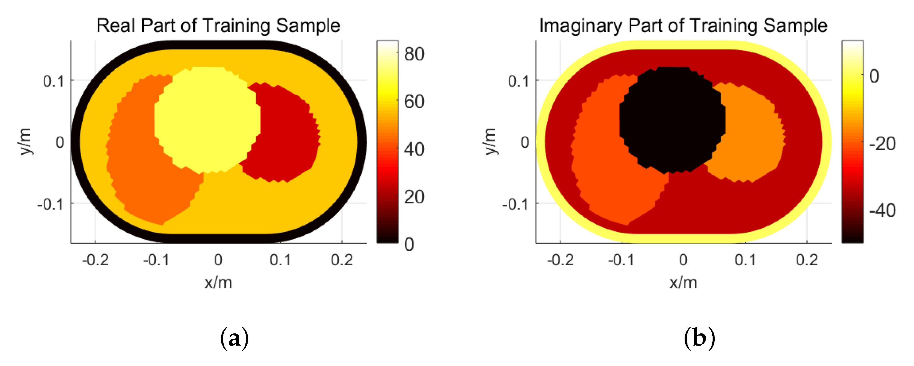
3.1. Description of Thorax Model

The goal of thorax imaging is the inversion of the distributions of dielectric properties in the human thorax. The main task is to reconstruct the lungs and heart. For simplicity, a homogeneous background is used as an initial model in the following discussions, which is shown in Figure 2. 2-D delta sources are placed on the boundary between free space and muscle. As it is infinitely long in the z-direction, the electric field in is the TM mode. The dielectric properties of human tissues including muscle, lung, and heart are given in [46]. The relative permittivity and conductivity of muscle, inflated lung, and heart at 433 MHz and 915 MHz are shown in Table 1. The dielectric properties of muscle are used for background.
The numerical experiments including forward modeling and inversion are all carried out with Matrix Laboratory (MATLAB® R2017b). When solving the forward problem, the model is partitioned into 4862 triangular elements with 150 elements on the boundary, with a maximum side length less than 1 cm, which is 0.013 of the wavelength of 433 MHz in vacuum.

3.2. Training Set

Training samples are usually set according to prior information. As lungs and heart are the main reconstruction targets in thorax imaging, a 3-ellipse training model is adopted in this application. Two random ellipses represent two lungs and one random circle in the middle represents the heart. The position, size, dielectric properties and rotation angle of different, training samples vary in a predefined range. Figure 3 shows an example of training samples at 433 MHz.
The ranges of different parameters at 433 MHz and 915 MHz are shown in Table 2. It should be mentioned that the major axis of the two ellipses is in y-direction before rotation. So the rotation angle describes the angle between the major axis and y-direction. It is positive if the rotation is clockwise. Moreover, in clinical diagnosis, abnormalities may occur in only one of the two lungs, hence they may have different parameters. So the two ellipses share same variation range but the values of their parameters are different. SDM takes the advantage of prior information, so 3000 training samples are generated according to the rules above. Figure 4 shows the training misfit at two frequencies. Both converge after 10 iterations using SDM.

3.3. Numerical Experiments

3.3.1. Iterative SDM

After the training stage, a thorax model is used to test the algorithm, which is shown in Figure 5a,d. The two ellipses represent two lungs and the circle in the middle represents the heart. They are in different colors as they have different dielectric properties. During reconstruction, 5 % white noise is added to the testing data. The reconstructed relative permittivity distributions of the thorax model at 433 MHz are shown in Figure 5b,e. The red and yellow parts in Figure 5b represent reconstructed size and the real part of relative permittivity of lungs and hearts respectively. The orange and black parts in Figure 5e show the reconstructed imaginary part of relative permittivity. The data misfit of reconstruction process is shown in Figure 6. With 10 iterations, a thorax model is reconstructed and the reconstruction process converges. The position, size, and rotation of the lungs and heart can be reconstructed accurately. The reconstruction at 915 MHz is also tested, which is shown in Figure 7.

3.3.2. One-Step SDM

As mentioned before, the iteration process is adopted to overcome the nonlinearity in thorax imaging, which can be computationally expensive and difficult to implement for real-time imaging. In clinical diagnosis, respiration is continuous, which means the dielectric properties of lungs are changing all the time. As a result, thorax imaging with a high temporal resolution is necessary. The convergence of data misfit during training and testing shows that the data misfit decreases significantly at the first iteration, which means keeping only the first step of SDM may also have a reasonable performance. One-step SDM retains the advantage of iterative SDM in the incorporation of prior information and saves reconstruction time. Figure 5c,f show the reconstruction results using one-step SDM. Compared with iterative SDM, a similar performance of a reconstruction size, position, and rotation using one-step SDM is achieved. Lungs and heart can be distinguished from the reconstruction result. Although the value of reconstructed dielectric properties using one-step SDM are not so satisfying, the structural information of lungs and heart it provides can help doctors to monitor human respiration in clinical diagnosis, such as detecting level of atelectasis. Similar phenomenon can be seen for 915 MHz. The above results indicate that microwave real-time throax imaging may be feasible with the help of one-step SDM in the future.

3.4. Discussions

According to the results in numerical experiments, the feasibility of SDM on 2-D microwave thorax imaging is basically verified. With a training set containing models of three ellipses to mimic lungs and hearts, average descent directions can be learned for the inversion of a testing thorax model. SDM shows great capability in solving nonlinear inverse problem, which also shows prior information can play a significant role in inversion. Training sets need to be specially designed to achieve a better performance. In common applications, training samples can be generated simply according to possible shapes, sizes, positions, and dielectric properties of the real model. However, in thorax imaging, the relative permittivity and conductivity of heart are larger than those of background, while the opposite is true for lungs. The average descent direction for heart and lungs is different. As a result, the dielectric properties of the circle and ellipses are set to be larger and smaller than background respectively. Moreover, it should be noted that, the heart always lies between the two lungs in the front of the thorax. So the position of circles is set accordingly. More importantly, the overlap of position variation range between circle and ellipses should be relatively small to avoid learning and reconstruction mistakes in dielectric properties. If the ellipse is so large that it exceeds the thorax boundary, the exceeding parts should be removed.
The reconstruction results using 433 MHz and 915 MHz are not the same. The outline of heart and lungs is described more completely using low frequency. On the other hand, the separation between two lungs is clearer using 915 MHz, which means high frequency reconstruction focuses more on details. Reconstruction using two frequencies simultaneously may recover both outline and details at the same time. The results of dual-frequency one-step SDM are shown in Figure 8. Compared with single-frequency reconstruction, the structural information is more precise including both outline and details. Microwave at two frequencies shares the same structure during training and testing. As a result, inversion with dual-frequency can better reconstruct structural information than single-frequency reconstruction. In future, data with more frequencies may further improve the inversion.
This work mainly focuses on the reconstruction of dielectric properties changes in thorax caused by respiration. However the lung volume changes caused by thorax expansion and contraction during the respiration process may also affect the received signals. These factors should be further studied quantitatively in future studies.

4. Conclusions

In this paper, the application of one-step SDM in 2-D microwave thorax imaging was studied. A training set consisting of three ellipses was introduced to train the average update direction. After training stage, a numerical thorax model was used to test the algorithm. The results of numerical experiments verified its feasibility in thorax imaging. The results based on one-step SDM showed its potential to realize thorax imaging with a high temporal resolution, retaining adequate structural information for clinical diagnosis. In future, human respiration experiments will be conducted and one-step SDM will be adopted in experiments. The reconstruction of dielectric property distribution in human thorax will be further tested based on measured data using SDM.

Author Contributions

Project administration, H.Z. (Haolin Zhang), M.L., F.Y. and S.X.; Resources, H.Z. (Haolin Zhang); Software, H.Z. (Haolin Zhang), Y.Y. (Yan Yin), H.Z. (Hongyu Zhou), Y.Y. (Yubo Yang), S.Z. and J.S.; Supervision, M.L.; Writing—original draft, H.Z. (Haolin Zhang). All authors have read and agreed to the published version of the manuscript.

Funding

This research was funded by National Science Foundation of China (61971263), the National Key R&D Program of China (2018YFC0603604), Beijing Innovation Center for Future Chips, Tsinghua University and the Institute for Precision Medicine, Tsinghua University, Beijing, China.

Acknowledgments

The authors would like to thank Ke Zhang and Rui Guo from the Department of Electronic Engineering, Tsinghua University for their help and fruitful discussions on SDM.

Conflicts of Interest

The authors declare no conflict of interest.

Abbreviations

The following abbreviations are used in this manuscript:
CTComputed Tomography
CNNConvolutional Neural Network
DoIDomain of Interest
FE-BIFinite Element-Boundary Integral
ISMIndustrial, Scientific and Medical
MATLABMatrix Laboratory
MRIMagnetic Resonance Imaging
SDMSupervised Descent Method
TMTransverse Magnetic

References

  1. Fear, E.C.; Li, X.; Hagness, S.C.; Stuchly, M.A. Confocal microwave imaging for breast cancer detection: Localization of tumors in three dimensions. IEEE Trans. Biomed. Eng. 2002, 49, 812–822. [Google Scholar] [CrossRef] [Green Version]
  2. Meaney, P.M.; Fanning, M.W.; Dun, L.; Poplack, S.P.; Paulsen, K.D. A clinical prototype for active microwave imaging of the breast. IEEE Trans. Microw. Theory Tech. 2000, 48, 1841–1853. [Google Scholar] [CrossRef]
  3. Scapaticci, R.; Bucci, O.M.; Catapano, I.; Crocco, L. Robust microwave imaging for brain stroke monitoring. In Proceedings of the 2013 7th European Conference on Antennas and Propagation (EuCAP), Gothenburg, Sweden, 8–12 April 2013; pp. 75–78. [Google Scholar]
  4. Bisio, I.; Fedeli, A.; Lavagetto, F.; Luzzati, G.; Pastorino, M.; Randazzo, A.; Tavanti, E. Brain stroke detection by microwave imaging systems: Preliminary two-dimensional numerical simulations. In Proceedings of the 2016 IEEE International Conference on Imaging Systems and Techniques (IST), Chania, Greece, 4–6 October 2016; pp. 330–334. [Google Scholar] [CrossRef]
  5. Merunka, I.; Fiser, O.; Vrba, D.; Vrba, J. Numerical analysis of microwave tomography system for brain stroke detection. In Proceedings of the 2018 28th International Conference Radioelektronika (RADIOELEKTRONIKA), Prague, Czech Republic, 19–20 April 2018. [Google Scholar] [CrossRef]
  6. Semenov, S.; Seiser, B.; Stoegmann, E.; Auff, E. Electromagnetic tomography for brain imaging: From virtual to human brain. In Proceedings of the 2014 IEEE Conference on Antenna Measurements Applications (CAMA), Antibes Juan-les-Pins, France, 16–19 November 2014; pp. 1–4. [Google Scholar] [CrossRef]
  7. Ireland, D.; Bialkowski, K.; Abbosh, A. Microwave imaging for brain stroke detection using Born iterative method. IET Microw. Antennas Propag. 2013, 7, 909–915. [Google Scholar] [CrossRef]
  8. Celik, N.; Gagarin, R.; Youn, H.; Iskander, M.F. A Noninvasive Microwave Sensor and Signal Processing Technique for Continuous Monitoring of Vital Signs. IEEE Antennas Wirel. Propag. Lett. 2011, 10, 286–289. [Google Scholar] [CrossRef]
  9. Celik, N.; Gagarin, R.; Huang, G.C.; Iskander, M.F.; Berg, B.W. Microwave Stethoscope: Development and Benchmarking of a Vital Signs Sensor Using Computer-Controlled Phantoms and Human Studies. IEEE Trans. Biomed. Eng. 2014, 61, 2341–2349. [Google Scholar] [CrossRef]
  10. Rezaeieh, S.A.; Bialkowski, K.S.; Abbosh, A.M. Microwave System for the Early Stage Detection of Congestive Heart Failure. IEEE Access 2014, 2, 921–929. [Google Scholar] [CrossRef] [Green Version]
  11. Rezaeieh, S.; Zamani, A.; Bialkowski, K.; Mahmoud, A.; Abbosh, A. Feasibility of Using Wideband Microwave System for Non-Invasive Detection and Monitoring of Pulmonary Oedema. Sci. Rep. 2015, 5, 14047. [Google Scholar] [CrossRef] [Green Version]
  12. Iskander, M.F.; Durney, C.H. Electromagnetic techniques for medical diagnosis: A review. Proc. IEEE 1980, 68, 126–132. [Google Scholar] [CrossRef]
  13. Pedersen, P.C.; Johnson, C.C.; Durney, C.H.; Bragg, D.G. Microwave Reflection and Transmission Measurements for Pulmonary Diagnosis and Monitoring. IEEE Trans. Biomed. Eng. 1978, BME-25, 40–48. [Google Scholar] [CrossRef]
  14. Salman, S.; Wang, Z.; Colebeck, E.; Kiourti, A.; Topsakal, E.; Volakis, J.L. Pulmonary Edema Monitoring Sensor With Integrated Body-Area Network for Remote Medical Sensing. IEEE Trans. Antennas Propag. 2014, 62, 2787–2794. [Google Scholar] [CrossRef]
  15. Zamani, A.; Rezaeieh, S.A.; Abbosh, A.M. Lung cancer detection using frequency-domain microwave imaging. Electron. Lett. 2015, 51, 740–741. [Google Scholar] [CrossRef]
  16. Abdelhamid, M.M.; Allam, A.M. Detection of lung cancer using ultra wide band antenna. In Proceedings of the 2016 Loughborough Antennas Propagation Conference (LAPC), Loughborough, UK, 14–15 November 2016; pp. 1–5. [Google Scholar] [CrossRef]
  17. Camacho, L.M.; Tjuatja, S. FDTD simulation of microwave scattering from a lung tumor. In Proceedings of the 2005 IEEE Antennas and Propagation Society International Symposium, Washington, DC, USA, 3–8 July 2005; Volume 3A, pp. 815–818. [Google Scholar] [CrossRef]
  18. Mohammed, B.J.; Abbosh, A.M.; Mustafa, S.; Ireland, D. Microwave System for Head Imaging. IEEE Trans. Instrum. Meas. 2014, 63, 117–123. [Google Scholar] [CrossRef]
  19. Ahdi Rezaeieh, S. Wideband Microwave Imaging Systems for the Diagnosis of Fluid Accumulation in the Human Torso. Ph.D. Thesis, The University of Queensland, Brisbane, Australia, 2016. [Google Scholar]
  20. Trefna, H.; Persson, M. Antenna array design for brain monitoring. In Proceedings of the 2008 IEEE Antennas and Propagation Society International Symposium, San Diego, CA, USA, 5–11 July 2008; pp. 1–4. [Google Scholar] [CrossRef]
  21. Rezaeieh, S.A.; Abbosh, A.M. Wideband and Unidirectional Folded Antenna for Heart Failure Detection System. IEEE Antennas Wirel. Propag. Lett. 2014, 13, 844–847. [Google Scholar] [CrossRef]
  22. Nilavalan, R.; Craddock, I.J.; Preece, A.; Leendertz, J.; Benjamin, R. Wideband microstrip patch antenna design for breast cancer tumour detection. IET Microwaves, Antennas Propag. 2007, 1, 277–281. [Google Scholar] [CrossRef] [Green Version]
  23. Bahramiabarghouei, H.; Porter, E.; Santorelli, A.; Gosselin, B.; Popović, M.; Rusch, L.A. Flexible 16 Antenna Array for Microwave Breast Cancer Detection. IEEE Trans. Biomed. Eng. 2015, 62, 2516–2525. [Google Scholar] [CrossRef]
  24. Sugitani, T.; Kubota, S.; Toya, A.; Xiao, X.; Kikkawa, T. A Compact 4 × 4 Planar UWB Antenna Array for 3-D Breast Cancer Detection. IEEE Antennas Wirel. Propag. Lett. 2013, 12, 733–736. [Google Scholar] [CrossRef]
  25. Yun, X.; Fear, E.C.; Johnston, R.H. Compact antenna for Radar-based breast cancer detection. IEEE Trans. Antennas Propag. 2005, 53, 2374–2380. [Google Scholar] [CrossRef]
  26. Hagness, S.C.; Taflove, A.; Bridges, J.E. Wideband ultralow reverberation antenna for biological sensing. Electron. Lett. 1997, 33, 1594–1595. [Google Scholar] [CrossRef]
  27. Zhang, H.; Li, M.; Yang, F.; Xu, S. A feasibility study of microwave respiration monitoring. In Proceedings of the 2017 Sixth Asia-Pacific Conference on Antennas and Propagation (APCAP), Xi’an, China, 16–19 October 2017; pp. 1–3. [Google Scholar] [CrossRef]
  28. Zhang, H.; Chen, X.; Li, M.; Yang, F.; Xu, S. A Compact Dual-Band Folded-Cavity Antenna for Microwave Biomedical Imaging Applications. In Proceedings of the 2019 IEEE International Conference on Computational Electromagnetics (ICCEM), Shanghai, China, 20–22 March 2019; pp. 1–3. [Google Scholar] [CrossRef]
  29. Zhang, H.; Li, M.; Yang, F.; Xu, S.; Zhou, H.; Yang, Y.; Chen, L. A Low-Profile Compact Dual-Band L-Shape Monopole Antenna for Microwave Thorax Monitoring. IEEE Antennas Wirel. Propag. Lett. 2020, 19, 448–452. [Google Scholar] [CrossRef]
  30. Zamani, A.; Mobashsher, A.T.; Mohammed, B.J.; Abbosh, A.M. Microwave imaging using frequency domain method for brain stroke detection. In Proceedings of the 2014 IEEE MTT-S International Microwave Workshop Series on RF and Wireless Technologies for Biomedical and Healthcare Applications (IMWS-Bio2014), London, UK, 8–10 December 2014; pp. 1–3. [Google Scholar] [CrossRef]
  31. Mojabi, P.; LoVetri, J. Microwave Biomedical Imaging Using the Multiplicative Regularized Gauss–Newton Inversion. IEEE Antennas Wirel. Propag. Lett. 2009, 8, 645–648. [Google Scholar] [CrossRef]
  32. Shao, W.; Du, Y. Microwave Imaging by Deep Learning Network: Feasibility and Training Method. IEEE Trans. Antennas Propag. 2020, 68, 5626–5635. [Google Scholar] [CrossRef]
  33. Shah, P.; Chen, G.; Moghaddam, M. Learning Nonlinearity of Microwave Imaging Through Deep Learning. In Proceedings of the 2018 IEEE International Symposium on Antennas and Propagation USNC/URSI National Radio Science Meeting, Boston, MA, USA, 8–13 July 2018; pp. 699–700. [Google Scholar] [CrossRef]
  34. Shah, P.; Moghaddam, M. Super resolution for microwave imaging: A deep learning approach. In Proceedings of the 2017 IEEE International Symposium on Antennas and Propagation USNC/URSI National Radio Science Meeting, San Diego, CA, USA, 9–15 July 2017; pp. 849–850. [Google Scholar] [CrossRef]
  35. Gerazov, B.; Conceicao, R.C. Deep learning for tumour classification in homogeneous breast tissue in medical microwave imaging. In Proceedings of the IEEE EUROCON 2017—17th International Conference on Smart Technologies, Ohrid, Macedonia, 6–8 July 2017; pp. 564–569. [Google Scholar] [CrossRef]
  36. Salucci, M.; Marcantonio, D.; Li, M.; Oliveri, G.; Rocca, P.; Massa, A. Innovative Machine Learning Techniques for Biomedical Imaging. In Proceedings of the 2019 IEEE International Conference on Microwaves, Antennas, Communications and Electronic Systems (COMCAS), Tel-Aviv, Israel, 4–6 November 2019; pp. 1–3. [Google Scholar] [CrossRef]
  37. Xiong, X.; De la Torre, F. Supervised Descent Method and Its Applications to Face Alignment. In Proceedings of the 2013 IEEE Conference on Computer Vision and Pattern Recognition, Portland, OR, USA, 23–28 June 2013; pp. 532–539. [Google Scholar] [CrossRef] [Green Version]
  38. Guo, R.; Jia, Z.; Song, X.; Li, M.; Yang, F.; Xu, S.; Abubakar, A. Supervised Descent Method for Full-wave Microwave Imaging. In Proceedings of the 2019 Photonics Electromagnetics Research Symposium-Fall (PIERS-Fall), Xiamen, China, 17–20 December 2019; pp. 624–631. [Google Scholar] [CrossRef]
  39. Guo, R.; Song, X.; Li, M.; Yang, F.; Xu, S.; Abubakar, A. Supervised Descent Learning Technique for 2-D Microwave Imaging. IEEE Trans. Antennas Propag. 2019, 67, 3550–3554. [Google Scholar] [CrossRef]
  40. Guo, R.; Jia, Z.; Song, X.; Li, M.; Yang, F.; Xu, S.; Abubakar, A. Pixel-and Model-based Microwave Inversion with Supervised Descent Method for Dielectric Targets. IEEE Trans. Antennas Propag. 2020, 68, 8114–8126. [Google Scholar] [CrossRef]
  41. Guo, R.; Jia, Z.; Song, X.; Li, M.; Yang, F.; Xu, S.; Abubakar, A. Application of Supervised Descent Method to Parametric Level-set Approach. In Proceedings of the 2019 IEEE International Conference on Computational Electromagnetics (ICCEM), Shanghai, China, 20–22 March 2019; pp. 1–2. [Google Scholar] [CrossRef]
  42. Ma, Y.; Guo, R.; Li, M.; Yang, F.; Xu, S.; Abubakar, A. Supervised Descent Method for 2D Magnetotelluric Inversion using Adam Optimization. In Proceedings of the 2019 International Applied Computational Electromagnetics Society Symposium—China (ACES), Nanjing, China, 8–11 August 2019; Volume 1, pp. 1–2. [Google Scholar] [CrossRef]
  43. Guo, R.; Li, M.; Yang, F.; Xu, S.; Abubakar, A. Application of supervised descent method method for 2D magnetotelluric data inversion. Geophysics 2020, 85, WA53–WA65. [Google Scholar] [CrossRef]
  44. Guo, R.; Li, M.; Fang, G.; Yang, F.; Xu, S.; Abubakar, A. Application of supervised descent method to transient electromagnetic data inversion. Geophysics 2019, 84, E225–E237. [Google Scholar] [CrossRef]
  45. Li, M.; Zhang, K.; Guo, R.; Yang, F.; Xu, S.; Abubakar, A. Supervised Descent Method for Electrical Impedance Tomography. In Proceedings of the 2019 Photonics Electromagnetics Research Symposium—Fall (PIERS—Fall), Xiamen, China, 17–20 December 2019; pp. 2342–2348. [Google Scholar] [CrossRef]
  46. Gabriel, C. Compilation of the Dielectric Properties of Body Tissues at RF and Microwave Frequencies; Technical Report; King’s Coll London (United Kingdom) Department of Physics: London, UK, 1996. [Google Scholar]
Figure 1. An example of a 2-D inverse problem.
Electronics 10 00352 g001
Figure 2. Background model (yellow: Human; black: Free space).
Electronics 10 00352 g002
Figure 3. An example of training samples at 433 MHz: (a) Real Part; (b) Imaginary part.
Electronics 10 00352 g003
Figure 4. Training misfit: (a) 433 MHz; (b) 915 MHz.
Electronics 10 00352 g004
Figure 5. Thorax model for testing at 433MHz: (a,d) Real model; (b,e) 10-step reconstruction; (c,f) One-step reconstruction.
Electronics 10 00352 g005
Figure 6. Reconstruction data misfit: (a) 433 MHz; (b) 915 MHz.
Electronics 10 00352 g006
Figure 7. Thorax model for testing at 915 MHz: (a,d) Real model; (b,e) 10-step reconstruction; (c,f) One-step reconstruction.
Electronics 10 00352 g007
Figure 8. Reconstruction results of dual-frequency one-step supervised descent method (SDM): (a,c) 433 MHz; (b,d) 915 MHz.
Electronics 10 00352 g008aElectronics 10 00352 g008b
Table 1. Relative permittivity and conductivity of muscle, inflated lung, and heart.
Tissue433 MHz915 MHz
  ϵ r σ (S/m) ϵ r σ (S/m)
Muscle56.90.8055.00.95
Inflated Lung23.60.3822.00.46
Heart65.30.9859.81.24
Table 2. Ranges of different parameters in training sets at 433 MHz and 915 MHz.
433 MHz
Center
Position (m)
Major
Axis (m)
Minor
Axis (m)
Relative
Permittivity
Conductivity
(S/m)
Rotation
Angle (°)
Left Ellipse x ( 0.110 , 0.060 )
y ( 0.020 , 0.020 )
(0.140, 0.279)(0.140, 0.274)(10, 55)(0.2, 0.8)(−60, 60)
Right Ellipse x ( 0.050 , 0.130 )
y ( 0.020 , 0.020 )
(0.140, 0.277)(0.111, 0.207)(10,55)(0.2, 0.8)(−60, 60)
Circle x ( 0.020 , 0.040 )
y ( 0.030 , 0.080 )
Diameter
(0.080, 0.196)
(57, 87)(0.8, 1.2)0
915 MHz
Center
Position (m)
Major
Axis (m)
Minor
Axis (m)
Relative
Permittivity
Conductivity
(S/m)
Rotation
Angle (°)
Left Ellipse x ( 0.110 , 0.060 )
y ( 0.020 , 0.020 )
(0.140, 0.278)(0.140, 0.274)(10, 55)(0.35, 0.95)(−60, 60)
Right Ellipse x ( 0.050 , 0.130 )
y ( 0.020 , 0.020 )
(0.140, 0.279)(0.111, 0.208)(10, 55)(0.35, 0.95)(−60, 60)
Circle x ( 0.020 , 0.040 )
y ( 0.030 , 0.080 )
Diameter
(0.080, 0.199)
(55, 85)(0.95, 1.35)0
Publisher’s Note: MDPI stays neutral with regard to jurisdictional claims in published maps and institutional affiliations.

