Article

DC Current Limiting Operation and Power Burden Characteristics of a Flux-Coupling Type SFCL Connected in Series between Two Windings

1
Industry-University Cooperation Foundation & Regional-Industrial Application Research Institute, Kongju National University, 1223-24, Cheonandae-ro, Cheonan 31080, Korea
2
Department of Aero Materials Engineering, Jungwon University, Goesan-gun 28024, Korea
3
Department of Electrical Engineering, Soongsil University, 369, Sangdo-ro, Dongjak-gu, Seoul 06978, Korea
*
Author to whom correspondence should be addressed.
Submission received: 16 April 2021 / Revised: 30 April 2021 / Accepted: 2 May 2021 / Published: 4 May 2021

Abstract

:
In this paper, a DC fault short circuit was conducted to analyze the DC fault current limiting characteristics of a flux-coupling type superconducting fault current limiter (SFCL) that has two coils connected in series via one iron core. Similar to the AC power system, the flux-coupling type SFCL in a DC system, which has the two coils connected with each other in series and the secondary coil connected with the superconducting element in parallel, remains in the superconducting state before a short-circuit accident occurs. This results in magnetic flux getting generated by the two windings connected in series offsetting each other and the induced voltage at the two windings remaining at zero. However, in the event of a short-circuit accident on the DC line, a resistance is generated on the superconducting element, so that the magnetic flux generated at the two windings no longer offsets each other. Therefore, a voltage is induced on the two windings, and the fault current is limited accordingly. As a result of configuring a DC short-circuit device and experimenting with this SFCL, we could confirm the DC fault current limiting effect of a flux-coupling type SFCL with two windings connected in series. In addition, we could establish performance conditions of the flux-coupling type SFCL in a DC system by inferring the fault current, operating current, and limited impedance equations according to the connection direction of the flux-coupling type SFCL with two windings connected in series and by analyzing fault current limiting degree, power burden, magnetic flux, and energy consumption for each element composing the SFCL.

1. Introduction

The increase in power demand and power supply facilities in DC systems, as well as AC systems, has increased the fault current of the system, and in an increasing number of places, the short-circuit capacity of existing circuit breakers is exceeded. As a result, the development of a superconducting fault current limiter (SFCL) can reduce the cost of replacing existing breakers as well as limit the fault current faster [1,2,3,4]. The features of superconductivity are that the resistance disappears under the three specific conditions of temperature, electric field, and magnetic flux, and they have completely diamagnetic characteristics. A superconductor having such superconductivity has no loss even when passing current, and it can send a large amount of current, unlike ordinary conductors. Superconducting power devices include cables, transformers, and current limiters developed using superconductors whose electrical resistance becomes zero under a certain temperature. SFCL is a device that limits the fault current generated in the power system by using a superconductor. In the event of an accident such as a wire break or a lightning strike, it detects several tens of times the fault current within 1 ms and converts it into a normal current within a few seconds, preventing large-scale accidents such as power outages. High-temperature SFCL is attracting attention because it can detect a self-accident current while operating at a high speed. When the SFCL operates with an existing breaker whose capacity is expected to be exceeded, the cost of device replacement can be avoided, the device can be miniaturized, and the system can be stabilized while being environment-friendly. There are many cases of real-life applications and the benefits reported across the world [5,6,7,8].
Recently, a number of high-capacity distributed power sources have been introduced as a result of making the system a smart grid for efficient operation of the distribution system. This may result in further increasing the fault current of the system. In the event of a short-circuit accident, unlike in AC current, there is no natural current zero; therefore, instead of a common mechanical type breaker, a high-speed DC breaker that can handle a very large and fast rise in DC fault current is essential [9,10,11,12,13]. However, when the rating of the system increases, the performance and capacity of mechanical high-speed switches and power semiconductor switches need to be increased accordingly to reliably shut off the increased fault current. This will increase the overall cost and size of DC breakers. Therefore, construction consisting only of DC breakers has limitations, and to address this, the need to apply current limiting technology that limits the DC fault current is increasing [14,15].
SFCL, a typical current-limiting technology, is highly advantageous owing to its superconducting properties and can reduce fault current quickly and efficiently in the right place in the event of a line-to-ground fault or a failure [16,17,18]. Most SFCL prototypes have been designed for AC systems [19,20,21,22,23,24,25,26,27]; however, R&D and basic research on the application of SFCL in DC systems is still in the early stages [28,29,30,31,32]. The topics of some published papers have been limited to evaluating optimization and economic feasibility and focus on deriving impedance values without considering the recovery characteristics of SFCL [33,34,35,36,37,38,39]. They also analyze DC current-limiting factors focusing on simulations rather than experiments to present applications [40,41,42,43,44].
In order to apply SFCL to an AC or DC power system, the first task to be solved is to increase the capacity of a superconductor. A common way to increase the capacity is to use a series-parallel connection between superconductors. However, this method faces a technical limitation of having a non-uniform threshold current value even if it is precisely manufactured by the same process. In order to overcome this problem, a flux-coupling type SFCL structure can be an optimal alternative among several superconducting current limiters. Therefore, in this paper, we intended to analyze the fault current-limiting effect of a flux-coupling type SFCL that has two coils connected in series via one iron core for inducting simultaneous quenching to reach a uniform power burden on the superconducting elements that make up flux-coupling type SFCL in a DC system when its capacity is increased. DC-simulated short-circuit experiments were conducted using an experimental circuit comprising high-temperature superconducting elements and coils. We inferred the fault current and operation current and the limited impedance-inducing equation for each connection direction of the flux-coupling type SFCL connected in series between two coils. We intended to measure the quench of superconducting elements from a simulated DC short-circuit experiment and to compare and analyze the current and voltage relationships of flux-coupling type SFCL and the changes in various characteristics of each winding before and after the fault. This paper is structured as follows. First, the description of the concept of flux-coupling type SFCL is briefly resumed in Section 2.1. Section 2.2 describes the experimental setup, including test circuits and data collection systems. In Section 3, the experimental evaluation factors according to the wiring direction between the two windings are analyzed respectively. Finally, the experimental results are described in Section 4.

2. Experimental Methods

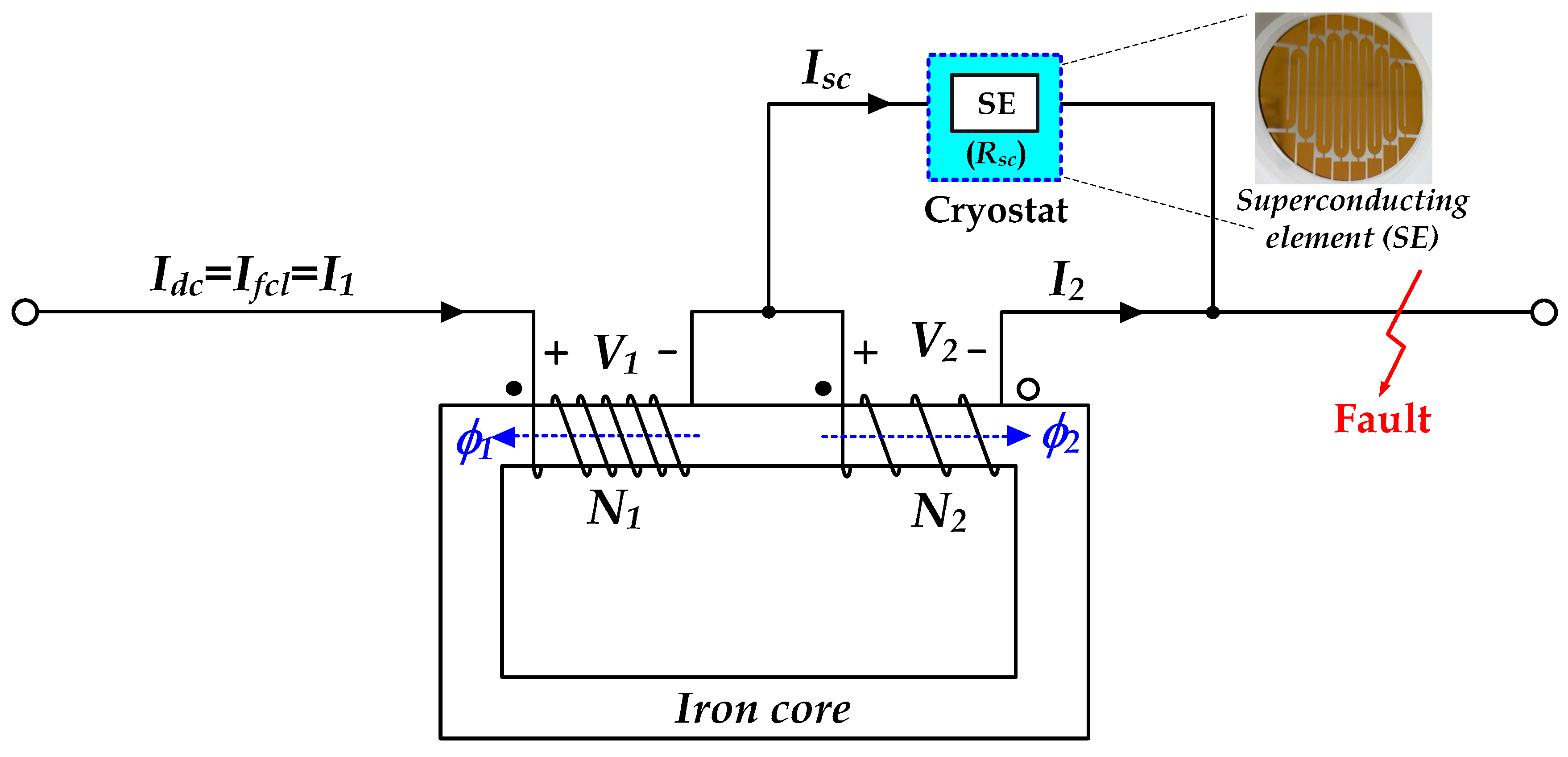
2.1. Operational Principle and Equivalent Circuit Analysis

Figure 1 shows the structure of a flux-coupling type SFCL that is connected in series between the primary and secondary coil. The primary and secondary coils used square wires, which are general conductors, not superconductors. It was designed to have a sufficient cross-sectional area (A = 12 mm2) in consideration of the current capacity. These two coils are connected in series to one iron core, and the superconducting element (SE) is connected in parallel with one of the two coils. An important parameter of SFCL is the direction of the coil winding of the iron core. The direction of the coil may be divided into additive winding and subtractive winding depending on the direction of connection of the primary winding (N1) and the secondary winding (N2). If the two magnetically coupled windings show the same polarity, it indicates the same direction, and if they show the opposite polarity, it indicates the reverse direction. To indicate polarity direction, the primary and secondary windings are marked with [●] and [○], as shown in Figure 1. In the case of additive winding, the same direction indicates the voltage of the primary winding (V1 [●]) and the voltage of the secondary winding (V2 [●]). In the case of subtractive winding, the reverse direction means the voltage of the primary winding (V1 [●]) and the voltage of the secondary winding (V2 [○]).
The SE, after patterning Y1Ba2Cu3O7-x (YBCO) thin film, was used as a component of the flux-coupling type SFCL (see Figure 1). The critical properties of SE were critical temperature 87 K and critical current 27A, and short-circuit experiments of flux-coupling type SFCL were conducted by immersing in 77 K liquid nitrogen. The YBCO thin film used in making the SE in this experiment was a sample purchased from German company THEVA. The 0.3 μm YBCO thin film was deposited on a 2-inch diameter sapphire substrate, and a 0.2 μm thick layer of gold is covered over it for by-pass for hotspots. The SE was made using photolithography consisting of 14 stripes, each of which is different in length, by etching the YBCO thin film into a 2 mm wide and 420 mm long diagonal line [45,46,47].
The operating principles can be explained to a great extent by separating them before and after the accident. Before the accident, the SE has zero resistance (Rsc) because the SE is at the superconducting state, and the magnetic fluxes (ϕ1, ϕ2) that are induced at each winding are offset against each other, and the voltage induced at each winding remains zero. After the accident, if a line-to-ground fault occurs on the DC line after the accident, the current flowing to the SE goes beyond the critical value to be transferred to normal conduction, which results in resistance at the SE, and then this generates a voltage at both ends of the SE. The voltage induced at the two windings causes a current limit impedance (Zfcl), which limits the fault current (Ifcl). In case of a failure on the load side, the current Idc flowing through the DC side becomes the same as the fault current Ifcl.
Figure 2 shows the electrical equivalent circuit of the flux-coupling type SFCL when the primary and secondary coils are connected in series. L1 and L2 represent the inductance of the primary and secondary coils, respectively. Idc, I1 and Ifcl refer to the current flowing in the DC-side line and the primary winding, and fault current in the event of a failure, with the values equal to each other. I2 and Isc represent current through the secondary winding and the SE. Vfcl represents the total DC voltage between two coils connected in series. Rsc and Vsc represent the resistance and voltage of the SE, respectively. It is assumed that there is no self-leakage flux on the primary and secondary sides of the two coils, but only mutual flux exists. When the mutual inductance was = k L 1 L 2 , we assumed that the coefficient of coupling k = 1 and M = L 1 L 2 . From the electrical equivalent circuit, the Kirchhoff’s voltage–current equation is established as follows.
V 1 = j ω L 1 I 1 ± j ω M I 2
V 2 = ±   j ω M I 1 + j ω L 2 I 2 = ± R s c I s c
V f c l = V 1 ± V 2 = V 1 ± V s c
I d c = I f c l = I 1 = I 2 + I s c
Here, the polarity of mutual inductance, secondary winding voltage, and SE were represented with (+) for additive winding and (−) for subtractive winding.
From Equations (1)–(4), we can infer the fault current of SFCL in the case of failure (Ifcl), SFCL operating current (Iop), and limited impedance (Zfcl) are as follows.
I d c = I f c l = I l = ± R s c + j ω L 2 j ω ( L 2 ± M ) I s c
I o p = ( 1 1 ± L 1 L 2 ) I c = ( 1 1 ± L ) I c
Z f c l = V f c l I f c l = ± j ω R s c ( L 1 + L 2 ) + 2 j ω M R s c ± R s c + j ω L 2
In Equations (5) through (7), the plus sign above represents additive winding between the two winding lines, and the minus sign below represents subtractive winding, respectively. Equation (6) was also induced, immediately after the failure, by defining the initially limited current as operational current (Iop) when the current generated at the SE reaches the critical current (Ic) value, substituting RSC = 0, Isc = Ic, Ifcl = Iop, we found that by adjusting the inductance ratio (L) of two coils in Equations (6) and (7), it is possible to establish the operating current and the limited impedance of the SFCL. In the induced formula, L represents the inductance ratio (L1/L2) of two coils.

2.2. Experimental Design and Methods

Figure 3 shows the composition of an experimental device to measure the DC fault current-limiting characteristics of SFCL connected in series between two windings using two magnetically coupled coils. It was designed with AC input voltages of Eab = Ebc = Eca = 80 Vrms, at 60 Hz, and DC power would be supplied via a three-phase diode and filter capacitor. Line resistance (Rline) and line inductance (Lline) were 0.42 Ω and 0.18 mH, respectively, and the fault resistance (Rf) was 1.5 Ω and load resistance (RL) was 10 Ω. The current (Idc) flowing through the DC side in a failure condition on the load side becomes equal to the fault current (Ifcl). Fault current (Ifcl) flowing through a flux-coupling type SFCL connected in series between two coils is approximately equal to the short-circuit current (If) caused by the short-circuit accident on the load side.
The SFCL circuit was constructed by connecting two windings in series on one iron core with the SE in parallel between the primary and secondary windings. This flux-coupling type SFCL was installed between the power side and the load. The inductance of the primary and secondary windings used in the short-circuit experiments was 1.3 mH and 60.9 mH, respectively. An SE composed of a YBCO thin film patterned was immersed in a 77 K liquid nitrogen container, and simulated short-circuit testing was carried out. The thin film had been manufactured by the German company THEVA. In the short-circuit accident simulation, DC power was initially supplied through a three-phase rectification circuit by switching SW1 on and charging DC voltage into capacitor C, as shown in Figure 3. SW2 was turned on at 100 ms, and SW3 was turned on only at 300–400 ms to generate a mock failure. The current and voltage flowing through each winding, including the voltage at two endpoints of the SE, were measured using a current transformer and a potential transformer. Table 1 shows the design specifications of the AC side power, each component of the DC-side power system, and each winding that makes up the SFCL and SE for performing the DC simulated short-circuit experiment.

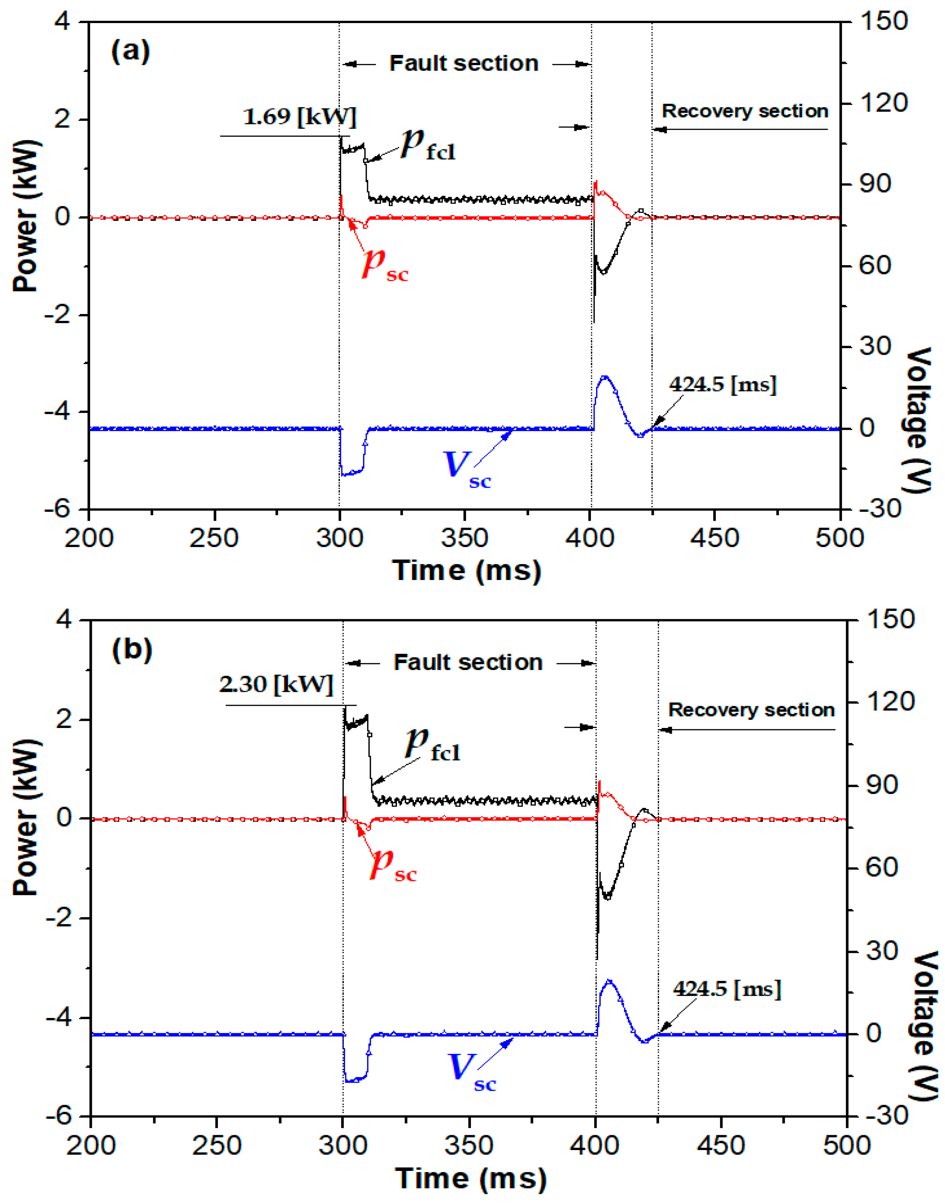
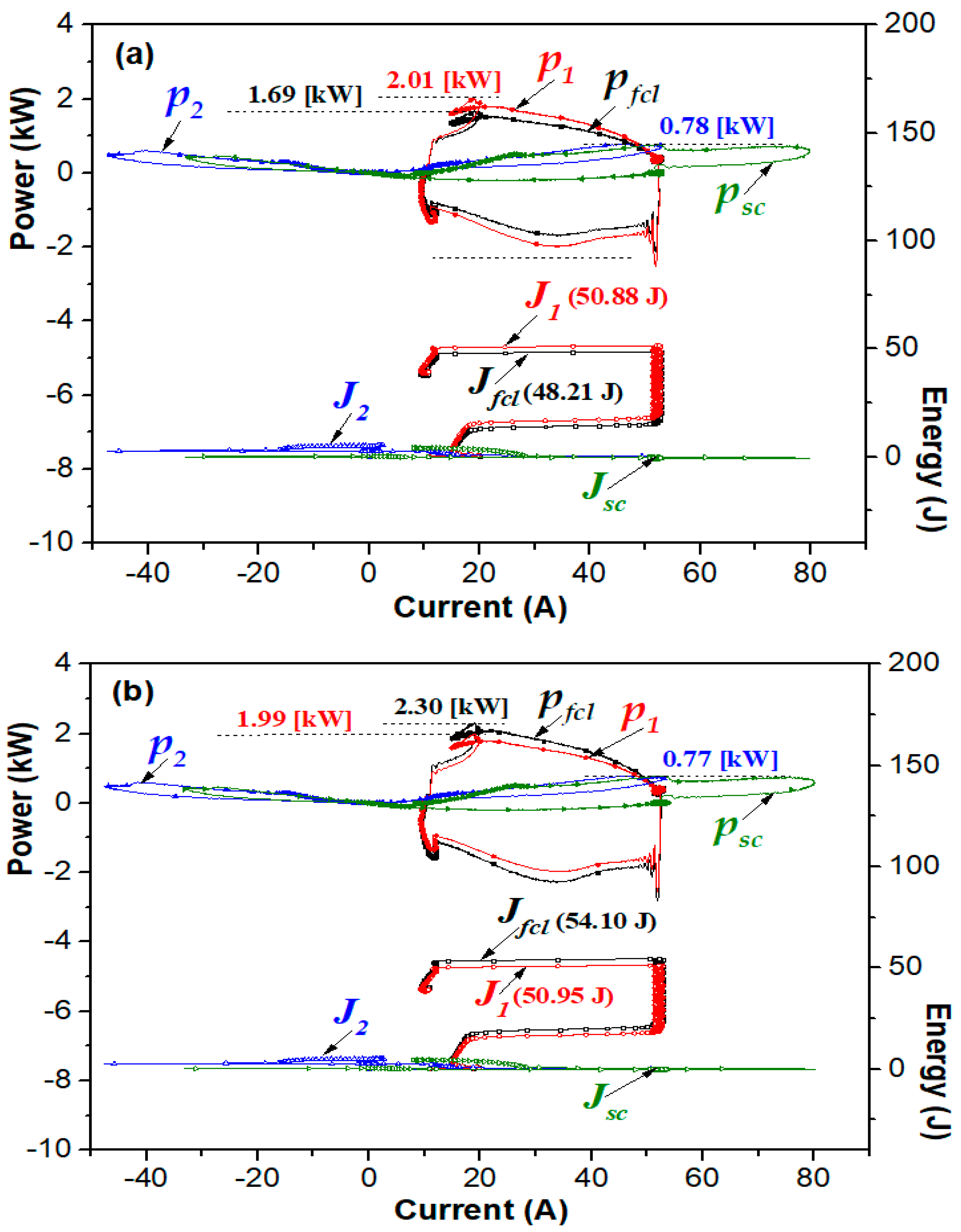
3. Experimental Results

Figure 4 shows the DC fault current-limiting characteristics of a flux-coupling type SFCL connected in series between two coils corresponding to the direction of winding between the primary and secondary windings. We can see that before the failure, the magnetic flux inside the iron core is offset against each other, the voltage of each winding is maintained at zero, and the voltage at both ends of the SE is built due to the quench generated in the SE at the same time as the failure of the DC line side. We can observe that the voltages (V1, V2) of the two windings are induced. In addition, the DC fault current immediately after the failure is shown to be more limited in the presence of a flux-coupling type SFCL than its absence.
Figure 4a shows the additive winding case where the two windings are wound in the same direction and Figure 4b shows the subtractive winding case where the two windings are wound in the opposite direction. We can see that in the case of both additive winding and subtractive winding, the voltage at SE and the primary winding direction of the two windings increases rapidly due to the quench of the SE right after the DC failure. In particular, immediately after the DC failure, the overall voltage of the SFCL (Vfcl) is greater in the case of subtractive winding than that in the case of additive winding. The overall voltage of SFCL (Vfcl) with additive and subtractive winding can be represented as the sum of the primary winding voltage (V1) and the secondary winding voltage (V2) and the difference between V1 and V2 respectively, which is consistent with Equation (3).
Immediately after the DC failure, the degree of limiting DC fault current was approximately the same regardless of the direction of the two windings, and the fault current-limiting operation occurred only while the SE was quenched. Transient voltage generation and transient current flow once again occurred at the primary and secondary windings at time points between 400 and 424.5 ms, when the failure was terminated. From this phenomenon, we assume that the moment switch SW3 is opened, as shown in Figure 3, instantaneous overvoltage and overcurrent occur due to the residual magnetism in the iron core, and the coil gradually returns to normal as the residual magnetism dissipates after 424.5 ms. We set this section to be the transient section or the recovery section. In order to completely shut off the fault current at the DC breaker after the fault current is limited in the event of a DC failure, the DC breaker needs to be able to operate immediately in the section where the fault current is reduced by the SFCL. In order to secure the shut-off time so that the DC breaker can have enough time to shut off the fault current, it is necessary to extend the time of the flux-coupling type SFCL limiting DC fault current. Furthermore, research on preventing or quickly dissipating the residual magnetism via a flux-coupling type SFCL is required because it continues to generate even though the failure is terminated.
Figure 5 shows the relationship curve between the current flowing at the primary and secondary winding and the SE and the SE voltage by the direction of the winding of the two coils (additive polarity winding and subtractive polarity winding).
Figure 5a shows the current and SE voltage characteristics flowing on both windings and SE in the case of additive polarity winding with two coils wound in the same direction. For the period between 300 and 310.2 ms immediately after the failure, the occurrence of the quench caused the SE voltage to be induced as the SE exceeded the critical current. At this point, the fault current Ifcl is the sum of the current flowing through the secondary winding and the current flowing through the SE, where the current flowing through the secondary winding was slightly greater than that through the SE. Before the failure, it was observed that the DC current did not flow through the secondary winding but mostly through the primary winding and the SE. This is because the SE did not exceed the critical current and did not generate a quench and the resistance remained zero. From 310.2 to 400 ms, at the end time point of the quench generation in the SE, there is little current flowing through the secondary winding, and most current flows through the SE.
Figure 5b shows the case of subtractive polarity winding where the two coils’ winding is wound in the opposite direction. The relationship curves between the currents flowing through the primary and secondary coils and the SE and the voltage of superconducting element are similar regardless of the direction of the two coils’ windings. At 400–424.5 ms at the end time point of the simulated DC short-circuit accident, it is observed that residual magnetism remaining in the iron core and the coils causes instantaneous overvoltage and overcurrent. After the 424.5 ms time point, they return to normal due to the gradual dissipation of the residual magnetism.
Figure 6 shows the relationship of the consumption of the instantaneous power (pfcl, psc) of a flux-coupling type SFCL relative to the SE voltage (Vsc) according to the winding direction of two windings during the failure. Immediately after the failure, the total power consumption (pfcl) of the SFCL with the subtractive winding was higher than that with the additive winding. However, the instantaneous power consumed by the SE was similar. The total power consumption (pfcl) of the SFCL with the subtractive winding was higher than that with the additive winding when the failure was terminated at the time point of 400 to 424.5 ms. Furthermore, residual magnetism in both coils was found to affect the instantaneous power consumed in the SE.
Figure 7 shows the characteristics of magnetic flux (ϕ1, ϕ2) and the power burden of instantaneous power (p1, p2) of the two windings when connected by additive winding and subtractive winding during the failure period. The magnetic fluxes (ϕ1, ϕ2) of the primary and secondary windings were similar in size regardless of the two coils’ winding directions, and the magnetic flux (ϕ1) of the primary winding is greater than the magnetic flux (ϕ2) of the secondary winding. We can observe that immediately after the failure, the maximum instantaneous power consumed in the secondary winding with the additive winding is slightly greater than that with the subtractive winding. In addition, the instantaneous power consumed in the primary winding during the period of failure was almost equal between the additive and the subtractive winding.
Figure 8 shows the power consumption and energy consumption characteristics of each component of the flux-coupling type SFCL relative to the current during the fault section and recovery section (300–424.5 ms) of the flux-coupling type SFCL connected in series between two coils in the case of the connection between the primary winding and the secondary winding with additive polarity or subtractive polarity.
The maximum power consumed and energy consumed by the SE during the fault section and the recovery section was almost the same whether connected with additive polarity or subtractive polarity. The maximum power consumed in a flux-coupling type SFCL consisting of two windings and SE is shown to be larger by 0.61 kW in the case of subtractive polarity winding than additive polarity winding. The maximum power consumed in the primary winding and the secondary winding respectively was shown to be 0.02 and 0.01 kW higher in the case of additive polarity winding than subtractive polarity winding, respectively. The maximum energy consumed in the flux-coupling type SFCL is found to be 5.89 J higher in the case of subtractive polarity winding than additive polarity winding. The maximum energy consumed in the primary winding was 0.07 J lower in the case of additive polarity winding than subtractive polarity winding, but the maximum energy consumed in the secondary winding was not much different between additive polarity winding and subtractive polarity winding.
To summarize the research contents, a DC short-circuit accident experiment was performed on a magnetic flux-coupled SFCL connected in series between two coils and one coil and a superconducting element in parallel. It was confirmed that the DC fault current limiting operation was performed well for 300 to 310 ms of DC fault occurrence regardless of the winding direction of the two coils However, at the end of the failure of 400–424.5 ms, it was not able to immediately recover to the normal state, and a transient state occurred. This is due to residual magnetism remaining in one iron core and coils, and it is necessary to study a plan to reduce the transient state in the future. In addition, the power consumption and energy consumption of each component device of the flux-coupling type SFCL before and after the occurrence of a failure were examined along the wining direction. Through waveform analysis, the total power consumption and total maximum energy consumed in SFCL were slightly higher in the case of subtractive polarity winding than in the case of additive polarity winding. The power consumption and energy consumption of the superconducting element were similar to each other regardless of the wining direction, and the trajectory also maintained the same pattern.

4. Conclusions

In this paper, we built a flux-coupling type SFCL prototype connected in series between two coils to limit the DC fault current in a DC system and constructed a DC simulated short-circuit accident device for an experiment. We compared the characteristics of the fault current limiting and the power burden before and after DC failure according to the winding direction of the two coils. Regardless of the winding direction of the two coils, the degree of limiting DC fault currents was similar, and DC fault current limiting occurred only while the SE was quenched. In addition, during the DC fault section and the recovery section of 300–424.5 ms, the total power consumption of the SFCL was higher in the case of subtractive polarity winding compared to additive polarity winding, but the instantaneous power consumed in the SE was similar in both cases. The characteristic power consumption in the primary winding and the secondary winding was slightly higher in the case of additive polarity winding than that in the case of subtractive polarity winding. The total maximum energy consumed in the SFCL was shown to be higher in the case of the subtractive polarity winding than in the additive polarity winding. The total maximum energy consumed in the SFCL was shown to be higher in the case of the additive polarity winding than in the subtractive polarity winding. The maximum energy consumed in the primary winding was slightly higher in the subtractive polarity winding, but the maximum energy consumed in the secondary winding was similar regardless of the winding direction of the two coils. Furthermore, we could confirm that in windings of both polarities, the power consumption and energy consumption trajectories of each element had the same pattern.
We could confirm that a flux-coupling type SFCL connected in series between two coils can limit the fault current in a DC system. However, when a DC breaker is installed at the back of the SFCL, we believe that further research is needed for extending the time spent reducing the DC fault current so that the SFCL can completely block the limited current. In addition, because residual magnetism occurs even after the failure is terminated, further studies need to be conducted to find ways to reduce or quickly remove residual magnetism in the future.

Author Contributions

Writing—original draft preparation, S.-C.K.; Analysis of the experimental data, T.-H.H.; Writing—review and editing, S.-H.L. All authors have read and agreed to the published version of the manuscript.

Funding

This research was supported by Basic Science Research Program through the National Research Foundation of Korea (NRF) funded by the Ministry of Education (2018R1D1A1B07040471).

Data Availability Statement

The data presented in this study are available on request from the corresponding author.

Conflicts of Interest

The authors declare no conflict of interest.

References

  1. Hafner, J.; Jacobson, B. Proactive hybrid HVDC breakers: A key innovation for reliable HVDC grids. In Proceedings of the CIGRE the Electric Power System of the Future: Integrating Supergrids and Microgrids International Symposium, Bologna, Italy, 13–15 September 2011; pp. B4–B264. [Google Scholar]
  2. Dordizadeh, P.; Gharghabi, P.; Niayesh, K. Dynamic analysis of a fast-acting circuit breaker (Thompson) drive mechanism. J. Korean Phys. Soc. 2011, 59, 3547–3554. [Google Scholar] [CrossRef]
  3. Kim, W.S.; Hyun, O.b.; Park, C.R.; Yim, S.W.; Yu, S.D.; Yang, S.E.; Kim, H.S.; Kim, H.R. Dynamic characteristics of a 22.9 kV hybrid SFCL for short-circuit test considering a simple coordination of protection system in distribution networks. IEEE Trans. on Appl. Supercond. 2012, 22, 5601404. [Google Scholar]
  4. Xiang, B.; Luo, J.; Gao, L.; Liu, Z.; Geng, Y.; Wang, J.; Yanabu, S. Study on the parameter requirements for resistive-type superconducting fault current limiters combined with mechanical DC circuit breakers in hybrid AC/DC transmission grids. IEEE Trans. Power Deliv. 2020, 35, 2865–2875. [Google Scholar] [CrossRef]
  5. Pham, V.D.; Laumoud, Y.; Verhaege, T.; Fevrier, A.; Collet, M.; Bekhaled, M. Towards the superconducting fault current limiter. IEEE Trans. on Appl. Supercond. 1991, 6, 801–808. [Google Scholar]
  6. Ye, L.; Lin, L.Z.; Juengst, K.P. Application studies of superconducting fault current limiters in electric power systems. IEEE Trans. Appl. Supercond. 2002, 12, 900–903. [Google Scholar]
  7. Jiang, Z.; Wang, Y.; Dai, S.; Ma, T.; Yuan, X.; Liu, M.; Chen, H.; Wang, M.; Peng, C. Application and design of resistive SFCL in ±160 kV MMC-HV dc system. IEEE Trans. Appl. Supercond. 2019, 29, 5603505. [Google Scholar] [CrossRef]
  8. Sun, J.; Du, J.; Li, Y.; Mo, S.; Cai, Y.; Yuan, W.; Ma, T. Design and performance test of a 20-kV DC superconducting fault current limiter. IEEE Trans. Appl. Supercond. 2020, 30, 5600305. [Google Scholar] [CrossRef]
  9. Lee, H.Y. A Study on Fault Protection Scheme Using Fault Current Limiter and Circuit Breaker Considering Fault Current Characteristics of Voltage Source Converter HVDC System. Ph.D. Thesis, Hanyang Unversity, Seoul, Korea, 2020; pp. 1–172. [Google Scholar]
  10. Franck, C.M. HVDC circuit breakers: A review identifying future research needs. IEEE Trans. Power Deliv. 2011, 26, 998–1007. [Google Scholar] [CrossRef] [Green Version]
  11. Flourentzou, N.; Agelidis, V.G.; Demetriades, G.D. VSC-based HVDC power transmission systems: An overview. IEEE Trans. Power Electron. 2009, 24, 592–602. [Google Scholar] [CrossRef]
  12. Bucher, M.K.; Franck, C.M. Contribution of fault current sources in multi-terminal HVDC cable networks. IEEE Trans. Power Deliv. 2013, 28, 1796–1803. [Google Scholar] [CrossRef] [Green Version]
  13. Zhang, F.; Ren, Y.; Shi, Z.; Yang, X.; Chen, W. Novel hybrid DC circuit breaker based on series connection of thyristors and IGBT half-bridge submodules. IEEE Trans. Power Electron. 2021, 36, 1506–1518. [Google Scholar] [CrossRef]
  14. Chen, Y.; Liu, X.; Sheng, J.; Cai, L.; Jin, Z.; Gu, J.; An, Z.; Yang, X.; Hong, Z. Design and application of a superconducting fault current limiter in DC systems. IEEE Trans. Appl. Superconduct. 2014, 24, 5601305. [Google Scholar] [CrossRef]
  15. Chen, L.; Li, G.; He, H.; Chen, H.; Li, Y.; Ding, M.; Zhang, X.; Xu, Y.; Ren, L.; Tang, Y. Study on coordination of resistive SFCLs and hybrid-type circuit breakers to protect a HVDC system with LCC and VSC stations. IEEE Trans. Appl. Supercond. 2020, 30, 5600806. [Google Scholar] [CrossRef]
  16. Manohar, P.; Ahmed, W. Superconducting fault current limiter to mitigate the effect of DC line fault in VSC-HVDC system. In Proceedings of the International Conference on Power, Signals, Controls and Computation, Thrissur, India, 3–6 January 2012; pp. 1–6. [Google Scholar]
  17. Endo, M.; Hori, T.; Koyama, T.; Kaiho, K.; Yamaguchi, I.; Arai, K.; Mizoguchi, H.; Yanabu, S. Development of a superconducting fault current limiter using various high-speed circuit breakers. IET Electr. Power Appl. 2009, 3, 363–370. [Google Scholar] [CrossRef]
  18. Wei, Z.; Xin, Y.; Hong, W.; Yang, C.; Lan, J.; Li, Q. A new type of DC superconducting fault current limiter. IEEE Trans. Appl. Supercond. 2019, 29, 5602905. [Google Scholar] [CrossRef]
  19. Ko, S.C.; Lim, S.H.; Han, T.H. Analysis on fault current limiting and recovery characteristics of a flux-lock type SFCL with an isolated transformer. Physica C 2012, 484, 263–266. [Google Scholar] [CrossRef]
  20. Lim, S.H.; Ko, S.C.; Han, T.H. Analysis on current limiting characteristics of a transformer type SFCL with two triggering current levels. Physica C 2012, 484, 253–257. [Google Scholar] [CrossRef]
  21. Lim, S.H.; Kim, Y.P.; Ko, S.C. Effect of peak current limiting in series-connection SFCL with two magnetically coupled circuits using E-I core. IEEE Trans. Appl. Supercond. 2016, 26, 5600404. [Google Scholar] [CrossRef]
  22. Lim, S.H.; Ko, S.C. Comparison of peak current limiting in two magnetically coupled SFCLs using dual iron cores. IEEE Trans. Appl. Supercond. 2016, 26, 5600304. [Google Scholar] [CrossRef]
  23. Ko, S.C.; Han, T.H.; Lim, S.H. Analysis on current limiting characteristics according to the Influence of the magnetic flux for SFCL with two magnetic paths. J. Electr. Eng. Technol. 2014, 9, 1909–1913. [Google Scholar] [CrossRef]
  24. Ko, S.C.; Han, T.H.; Lim, S.H. Current-limiting and recovery characteristics of a flux-lock-type SFCL with two adjustable operational currents. J. Korean Phys. Soc. 2014, 65, 253–256. [Google Scholar] [CrossRef]
  25. Han, T.H.; Ko, S.C.; Lee, B.J.; Lim, S.H. Study on current limiting characteristics of a flux-lock type SFCL using series connected two coils with twice triggering operation. J. Electr. Eng. Technol. 2014, 9, 777–781. [Google Scholar] [CrossRef] [Green Version]
  26. Yan, S.; Ren, L.; Zhang, Y.; Zhu, K.; Su, R.; Xu, Y.; Tang, Y.; Shi, J.; Li, J. AC loss analysis of a flux-coupling type superconducting fault current limiter. IEEE Trans. Appl. Supercond. 2019, 29, 5603205. [Google Scholar] [CrossRef]
  27. Ko, S.C.; Han, T.H.; Lim, S.H. Magnetization and power losses characteristics due to variation in the number of windings of a bridge type SFCL with double HTSC elements. IEEE Trans. Appl. Supercond. 2021, 31, 5600505. [Google Scholar]
  28. Qiu, Q.; Xiao, L.; Zhang, Z.; Jing, L.; Liu, Q.; Zhang, G.; Xia, D. Design and test of 10kV/400A flux-coupling–type superconducting fault current limiting module. IEEE Trans. Appl. Supercond. 2018, 28, 5601806. [Google Scholar] [CrossRef]
  29. Li, Z.; Liang, S.; Ren, L.; Tan, X.; Xu, Y.; Tang, Y.; Li, J.; Shi, J. Application of flux-coupling-type superconducting fault current limiter on shipboard MVDC integrated power systems. IEEE Trans. Appl. Supercond. 2020, 30, 5601908. [Google Scholar] [CrossRef]
  30. Shu, J.; Wang, S.; Liu, T.; Jiao, N.; Wang, Y. A novel current-limiting circuit based on resistive-type SFCL for fault in DC power system. Microelectron. Reliab. 2018, 88–89, 1201–1205. [Google Scholar] [CrossRef]
  31. Lee, J.G.; Khan, U.A.; Hwang, J.S.; Seong, J.K.; Shin, W.J.; Park, B.B.; Lee, B.W. Assessment on the influence of resistive superconducting fault current limiter in VSC-HVDC system. Phys. C 2014, 504, 163–166. [Google Scholar] [CrossRef]
  32. Qiu, Q.; Xiao, L.; Zhang, J.; Zhang, Z.; Song, N.; Jing, L.; Zha, W.; Du, X.; Teng, Y.; Zhou, Z.; et al. Design and test of 40-kV/2-kA DC superconducting fault current limiter. IEEE Trans. Appl. Supercond. 2020, 30, 5602305. [Google Scholar] [CrossRef]
  33. Aly, M.M.; Mohamed, E.A. Comparison between resistive and inductive superconducting fault current limiters for fault current limiting. In Proceedings of the 2012 Seventh International Conference on Computer Engineering & Systems (ICCES), Cairo, Egypt, 27–29 November 2012; pp. 227–232. [Google Scholar]
  34. Ren, L.; Tang, Y.; Li, Z.; Chen, L.; Shi, J.; Jiao, F.; Li, J. Techno-economic evaluation of a novel flux-coupling type superconducting fault current limiter. IEEE Trans. Appl. Supercond. 2010, 20, 1242–1245. [Google Scholar] [CrossRef]
  35. Na, J.B.; Kim, Y.J.; Jang, J.Y.; Ruy, K.S.; Hwang, Y.J.; Choi, S.; Ko, T.K. Design and tests of prototype hybrid superconducting fault current limiter with fast switch. IEEE Trans. Appl. Supercond. 2012, 22, 5602604. [Google Scholar]
  36. Chen, L.; Chen, H.; Shu, Z.; Zhang, G.; Xia, T.; Ren, L. Comparison of inductive and resistive SFCL to robustness improvement of a VSC-HVDC system with wind plants against dc fault. IEEE Trans. Appl. Supercond. 2016, 26, 5603508. [Google Scholar] [CrossRef]
  37. Li, B.; Jing, F.; Jia, J.F.; Li, B. Research on saturated iron-core superconductive fault current limiters applied in VSC-HVDC systems. IEEE Trans. Appl. Supercond. 2016, 26, 5603805. [Google Scholar] [CrossRef]
  38. Garcia, W.L.; Tixador, P.; Raison, B.; Bertinato, A.; Luscan, B.; Creusot, C. Technical and economic analysis of the r-type SFCL for HVDC grids protection. IEEE Trans. Appl. Supercond. 2017, 27, 5602009. [Google Scholar]
  39. Xi, J.; Pei, X.; Song, W.; Xiang, B.; Liu, Z.; Zeng, X. Experimental tests of DC SFCL under low impedance and high impedance fault conditions. IEEE Trans. Appl. Supercond. 2021, 31, 5601205. [Google Scholar]
  40. Deng, C.; Zheng, F.; Chen, L.; Li, M.; Xia, P.; Li, S.; Long, Z.; Zhu, L.; Guo, F. Study of a modified flux-coupling-type superconducting fault current limiter for mitigating the effect of DC short circuit in a VSC-HVDC system. J. Supercond. Nov. Magn. 2015, 28, 1525–1534. [Google Scholar] [CrossRef]
  41. Liang, S.; Tang, Y.; Xia, Z.; Ren, L.; Chen, L.; Xu, Y.; Wang, Z.; Yan, S. Study on the current limiting performance of a novel SFCL in DC systems. IEEE Trans. Appl. Supercond. 2017, 27, 5601106. [Google Scholar] [CrossRef]
  42. Yang, J.; Fletcher, J.E.; O’Reilly, J. Short-circuit and ground fault analyses and location in VSC-based DC network cables. IEEE Trans. Ind. Electron. 2012, 59, 3827–3837. [Google Scholar] [CrossRef] [Green Version]
  43. Li, B.; He, J. Studies on the application of R-SFCL in the VSC-based DC distribution system. IEEE Trans. Appl. Supercond. 2016, 26, 5601005. [Google Scholar] [CrossRef]
  44. Li, B.; Wang, C.; Hong, W.; Yang, S.; Xin, Y. Modeling of the DC inductive superconducting fault current limiter. IEEE Trans. Appl. Supercond. 2020, 30, 5601105. [Google Scholar] [CrossRef]
  45. Kim, H.R.; Choi, H.S.; Lim, H.R.; Kim, I.S.; Hyun, O.B. Initial quench development in uniform Au/Y-Ba-Cu-O thin films. IEEE Trans. Appl. Supercond. 2001, 11, 2414–2417. [Google Scholar]
  46. Choi, H.S.; Hyun, O.B.; Kim, H.R.; Park, K.B. Switching properties of a hybrid type superconducting fault current limiter using YBCO stripes. IEEE Trans. Appl. Supercond. 2002, 14, 1833–1838. [Google Scholar] [CrossRef]
  47. Kim, Y.P.; Ko, S.C. DC current limiting characteristics of flux-coupled type SFCL using superconducting element connected in parallel in a DC system. Energies 2021, 14, 1096. [Google Scholar] [CrossRef]
Figure 1. Configuration of the SFCL connected in series between two coils.
Electronics 10 01087 g001
Figure 2. Electrical equivalent circuit of SFCL connected in series between two coils.
Electronics 10 01087 g002
Figure 3. A schematic diagram of an experimental device used to simulate a short-circuit test in the SFCL connected in series between two windings.
Electronics 10 01087 g003
Figure 4. Voltage and current relationship curves of the DC distribution system models, including the flux-coupled SFCL connected in series between two windings, according to the winding direction: (a) additive polarity winding; (b) subtractive polarity winding.
Electronics 10 01087 g004
Figure 5. Current and SE voltage relationship curves of the flux-coupling type SFCL connected in series between two windings according to the winding direction: (a) additive polarity winding; (b) subtractive polarity winding.
Electronics 10 01087 g005
Figure 6. Power burden and SE voltage relationship curves of the flux-coupling type SFCL connected in series between two windings according to the winding direction: (a) additive polarity winding; (b) subtractive polarity winding.
Electronics 10 01087 g006
Figure 7. Instantaneous power burden and magnetic flux in each winding of the flux-coupling type SFCL connected in series between two windings according to the winding directions: (a) additive polarity winding; (b) subtractive polarity winding.
Electronics 10 01087 g007
Figure 8. Current vs. power loss and energy consumption trajectories in each device of the flux-coupling type SFCL connected in series between two windings during the fault and recovery section (300–424.5 ms): (a) additive polarity winding; (b) subtractive polarity winding.
Electronics 10 01087 g008
Table 1. Experimental specifications of the DC system models, including the flux-coupling type SFCL.
SpecificationValueUnit
Power supplyAC voltage (Eab)80Vrms
DC voltage (Udc)117Vdc
Filter capacitorCapacitor (C)10,200μF
Line impedanceLine resistor (Rline)
Line inductance (Lline)
0.42
0.18
Ω
mH
LoadLoad resistor (RL)10Ω
Fault fireFault resistor (Rf)1.5Ω
Inductance of two coilsInductance 1 (L1)
Inductance 2 (L2)
60.9
1.3
mH
mH
Superconducting element (SE)Material
Critical temperature (Tc)
Critical Current (Ic)
YBCO
87
27
Thin film
K
A
Recovery TimeAdditive winding24.5ms
Subtractive winding24.5ms
Publisher’s Note: MDPI stays neutral with regard to jurisdictional claims in published maps and institutional affiliations.

