
Design and Hardware Implementation of a Simplified DAG-Based Blockchain and New AES-CBC Algorithm for IoT Security


Department of Electrical and Electronics Engineering, Chung-Ang University, Seoul 06974, Korea
*
Author to whom correspondence should be addressed.
Electronics 2021, 10(9), 1127; https://0-doi-org.brum.beds.ac.uk/10.3390/electronics10091127
Submission received: 1 April 2021
/
Revised: 5 May 2021
/
Accepted: 6 May 2021
/
Published: 10 May 2021
(This article belongs to the Special Issue IoT Security and Privacy through the Blockchain)
Abstract
:Recently, to enhance the security of the Internet of Things (IoT), research on blockchain-based encryption algorithms has been actively conducted. However, because blockchains have complex structures and process large amounts of data, there are still many difficulties in using the conventional blockchain-based encryption algorithms in an IoT system that must have low power consumption and be ultra-lightweight. In this study, to address these problems (1) we simplified the conventional Directed Acyclic Graph (DAG)-based blockchain structure, and (2) we proposed a new Advanced Encryption Standard (AES)-Cipher Block Chaining (CBC) algorithm with enhanced security by periodically changing the secret key and initialization vector (IV) in the conventional AES-CBC encryption algorithm. Because the DAG, which is the conventional blockchain structure, randomly transmits data to multiple blocks, there may be overlapping blocks, and the quantity of transmitted data is not limited; thus, the time and power consumption for encryption and decryption increase. In this study, a simplified DAG was designed to address these problems so that packets can be transmitted only to three blocks, without overlapping. Finally, to verify the effectiveness of the algorithm proposed in this paper, an IoT system consisting of 10 clients and one server was implemented in hardware, and an experiment was conducted. Through the experiment, it was confirmed that when the proposed AES-CBC algorithm was used, the time taken and the amount of power consumed for encryption and decryption were reduced by about 20% compared to the conventional AES-CBC algorithm.
1. Introduction
Recently, technologies such as artificial intelligence, big data, cloud computing, the Internet of Things (IoT), and network performance have improved with the advent of the hyper-connected era. Due to advances in these technologies, resources are increasingly virtualized for sharing. Networks are virtualized to share network resources or build a cloud environment. Although the number of applications using networks is increasing, network security remains inadequate. The IoT is a technology used to connect and control sensors through networks. This technology is used not only in industries but also in homes. When the IoT is used at home to connect and control home devices, such as consumer devices, security systems, and home appliances, it is known as a smart home system. However, individual devices connected to home systems can create security problems. The IoT is controlled through a network, and connected devices with weak security may suffer various types of damage by hackers. Vulnerabilities such as simple patterns of encryption, non-periodic password changes, old platforms, a lack of encryption algorithms, and a lack of security in network connections can be revealed. Using these vulnerabilities, personal information can be stolen to cause financial damage, and secondary damage such as the invasion of user privacy can also be caused through identifying life patterns. Today, the seriousness of the privacy invasion problem is increasing due to the increased number of single-person households. Furthermore, the vulnerability of the IoT is also steadily growing [1,2]. To address this problem, symmetric key algorithms such as the Advanced Encryption Standard (AES), Secure Hash Algorithm (SHA), and Lightweight Encryption Algorithm (LEA) with a block encryption structure have been applied to increase security [3,4]. However, these approaches make it easy to obtain cracked data [5]. In addition, security should be enhanced due to problems such as new malicious codes and denial of service [6]. Recently, the security of blockchains has been emphasized [7,8]. Much research has been conducted to improve security, but most studies have focused on improving security suitable for one-to-one communication. Blockchains have the advantage of being capable of enhancing security through verification between nodes, which makes forgery difficult. Consequently, research using blockchain techniques to develop robust security algorithms is actively underway [9,10,11,12,13,14,15].
In this study, the security of the IoT environment was improved using a blockchain-based algorithm. The algorithm was implemented by imitating the Directed Acyclic Graph (DAG) algorithm.
When a client connected to a particular sensor sends data, the encrypted data are randomly transmitted to other clients. The clients who receive the data decrypt and re-encrypt it before retransmitting the encrypted data to other clients and, finally, to the server. The server that receives the data decrypts and aggregates these data, and adopts the data that were verified the most. Encryption was performed using the AES algorithm, and the cipher key was set to be changed periodically. Consequently, using this method, problematic clients can be identified, and the inference of the cipher key is impossible, even when the data are exposed. The performances of the conventional AES-CBC algorithm and the proposed new AES-CBC algorithm were compared, and the overhead of the proposed algorithm was evaluated.
The remainder of this paper is organized as follows. In Section 2, related works are discussed, and in Section 3, the background technology of the DAG-based blockchain structure and AES-CBC algorithm is explained. In Section 4, the proposed Simplified DAG-based Blockchain Structure is described, and in Section 5, the proposed new AES-CBC encryption algorithm is described. In Section 6, system configuration and hardware equipment are described, and in Section 7, experiments of encryption and decryptions, verification of encryption, and analysis of the proposed AES-CBC algorithm are described. Section 8 compares the conventional AES-CBC encryption algorithm with the proposed new AES-CBC encryption algorithm, and Section 9 presents the conclusion of the paper.
2. Related Work
Various studies have been conducted to build a system suitable for the IoT. For the current work, related studies were reviewed to address technical issues, such as security, reliability, and scalability.
Biswas et al. proposed a PoBT algorithm that enables block security at the stage of transaction verification and block generation. PoBT is a lightweight consensus algorithm that integrates peers according to the number of nodes participating in the session. The computational time required for peers is reduced, and the IoT transaction speed is enhanced by limiting resources. In addition, the memory required for IoT nodes is reduced using a distributed peer system [16].
Mohanty et al. developed an ELIB algorithm using a lightweight consensus algorithm, Certificateless (CC), and distributed throughput management (DTM), so that it can be applied to the IoT. To reduce the resources consumed, the number of blocks was limited, and the throughput of the consensus algorithm of the blockchain was also limited. As a result, the time and energy required to process the blocks were reduced [17].
Huang et al. proposed a credit-based proof of work (PoW). Power was limited through PoW to fit IoT devices, and a blockchain infrastructure with a DAG structure was built. Functionally, the nodes were divided into two categories: light and full nodes. Light nodes are IoT devices that are connected to the full nodes to interact, and the collected sensor data are subject to data authority management with AES block encryption. The full nodes have two roles, as an administrator and a gateway, and a secure blockchain system was implemented using AES block ciphers [18].
3. DAG-Based Blockchain Structure and AES-CBC Algorithm
3.1. Struture of DAG
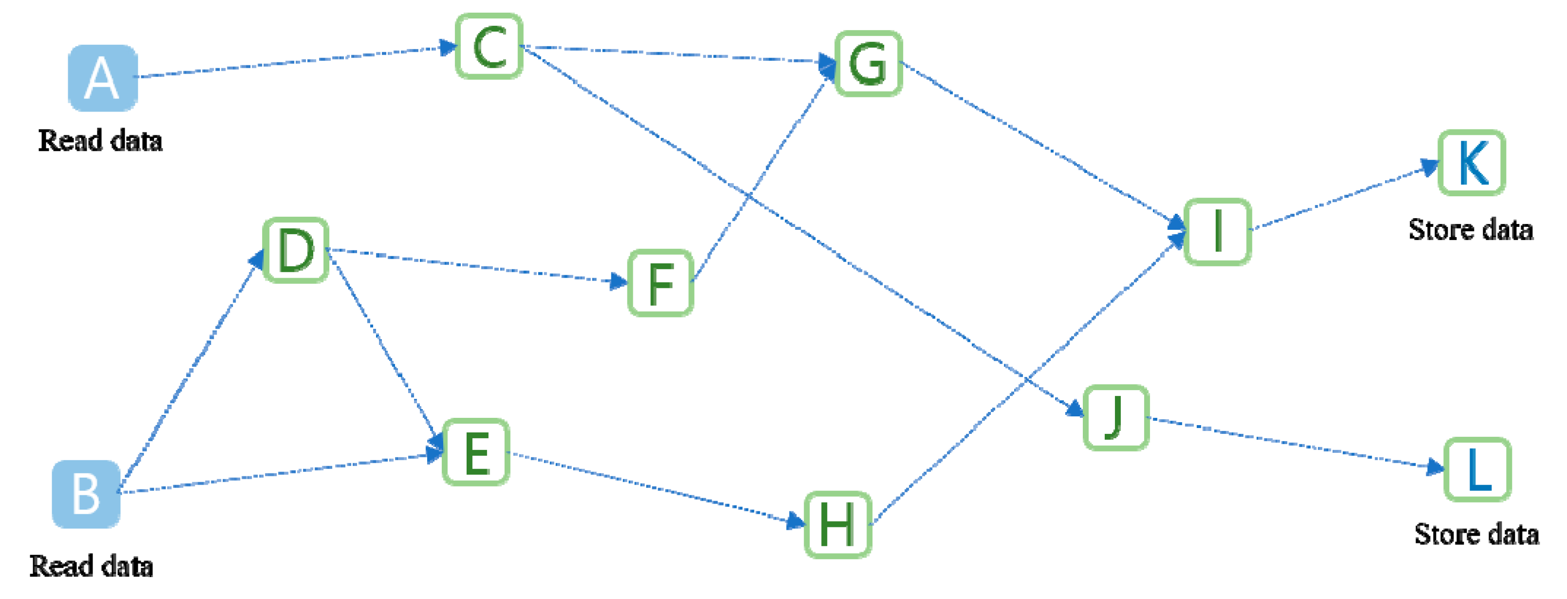
The structure of DAG is attracting attention as a core technology in the era of blockchain 3.0 [19,20,21,22,23]. Figure 1 shows a structure of the DAG. As a non-circulating directed graph, it has multi-directionality without any fixed order and continues in only one direction, as seen in the figure.
3.2. AES-CBC Algorithm
3.2.1. AES Algorithm
The AES algorithm was established by the National Institute of Standards and Technology and was the first algorithm that was approved for Top Secret use by the US National Security Agency [24]. The AES algorithm is a symmetric key algorithm that uses the same key in encryption and decryption processes. A symmetric key algorithm refers to an algorithm that uses the same cipher key for encryption and decryption. The encryption structure is composed of a Substitution–Permutation Network (SPN) structure and a Feistel structure. The AES algorithm uses the SPN structure, which is shown in Figure 2. In Figure 2, S represents the substitution box (S-box), and P represents the permutation box (P-box). Regarding the encryption process of the AES algorithm, ciphertexts are generated through many rounds of processes in the S-box and P-box. The S-box is a basic packet used for encryption, and its function realizes the non-linear substitution of data. The function of the P-box is changing the location of data. The SPN structure has the disadvantage that it must be designed to require an inverse function in the encryption and decryption processes, but has the advantage that it can be designed more efficiently than the Feistel structure because encryption and decryption are possible simultaneously without moving bits during the encryption process.
3.2.2. CBC Operating Mode
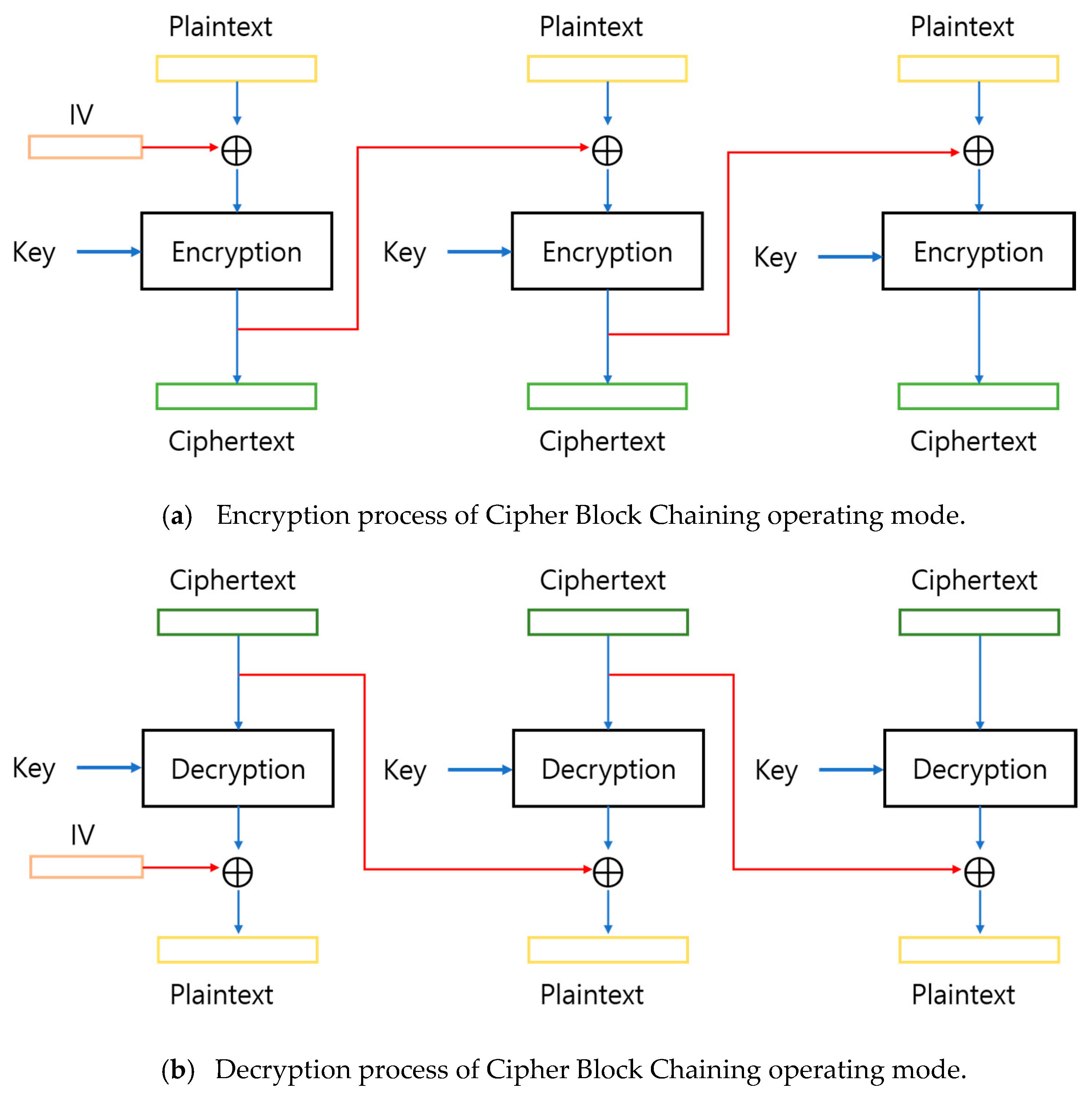
The block encryption technology has five operating modes: Electronic CodeBook (ECB) mode, Cipher Block Chaining (CBC) mode, Cipher FeedBack (CFB) mode, Output FeedBack (OFB) mode, and Counter (CTR) mode. The CBC mode is the most secure encryption method among block encryption operating modes and is the most commonly used. Figure 3 is a block diagram that shows the encryption and decryption processes in CBC mode [25]. In the CBC operating mode encryption process, as shown in Figure 3a, each block performs an XOR operation with the encryption result of the previous block before being encrypted, and in the case of the first block, the initialization vector (IV) is used. The decryption process in the CBC operating mode proceeds in the reverse order of the encryption process, as shown in Figure 3b. However, because the first block does not have the encryption result of the previous block, the ciphertext and the initialization vector (IV) are XOR operated [26,27].
4. Proposed Simplified DAG-Based Blockchain Structure
This paper proposes a structure suitable for the new IoT using simplified DAG-based blockchain.
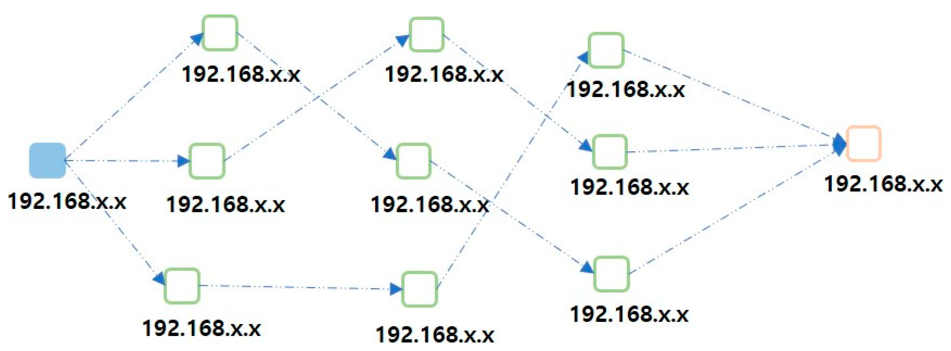
Figure 4 shows the structure of the simplified DAG-based blockchain. Unlike the DAG structure, the proposed simplified DAG-based blockchain structure generates paths randomly without any overlapping blocks. If memory usage increases, system resources may become insufficient and process efficiency may be degraded. In the case of the IoT, as the number of processes increases, the memory usage increases, leading to greater power usage, so that the efficiency may be reduced, and phase alignment is not performed. In this study, to address these problems, a new algorithm was constructed in which the same paths do not overlap in any node. That is, the final target point is reached without going to any node that has already been passed once. Regardless of which node it is, when an event has occurred in a node, paths are created to three nodes. A path is thus created to reach the destination through three paths between the nodes, and when an event has occurred, the paths between nodes are changed in no particular order.
The simplified DAG-based blockchain randomly transmits the ciphertext to three clients. Therefore, it is difficult to apply the algorithm to fewer clients. To solve this problem, clients are registered to the server to determine how to transmit the ciphertext to clients. In cases where the number of clients connected to the server is less than four, when an event occurs, the client determines the number of clients to which the ciphertext is to be transmitted as “zero”. Here, “zero” has no special meaning and was used to indicate that events that occurred in a random client are transmitted directly to the server without passing through other clients. Subsequently, the ciphertext is sent directly to the server without sending it to any client, and the decision is made without the procedure to check the number of clients from which data are received. When at least four clients are connected to the server, the client where the event has occurred transmits the ciphertext to other clients. The clients that receive the ciphertext decrypt the ciphertext, encrypt it again, include a message indicating that the current client has verified the data, and transmit it to the server. When clients are extended in this way, the transmission method is defined according to the number of clients. In this manner, the client where an event has occurred randomly transmits a message to three clients, and the transmission process can be carried out up to three times for each data packet. In our proposed simplified DAG-based blockchain structure, even if the number of clients increases, the number of clients for which the packets are verified is limited to nine at the maximum. This is because increasing the amount of data generated by the client can overload the system and cause network delays. The value of nine was verified as the optimal value through many experiments.
Table 1 shows the packet structure generated when an event occurs in a client. The packet structure is as follows. In the packet, Number “n” is the cumulative sum of the values of octet 4, which is the 4th digit of the IP address of the clients where the events occurred; Event Client Address “a” is the value of the octet 4, which is the 4th digit of the IP address of the client where the event occurred; and Random Address 1 “b”, Random Address 2 “c”, and Random Address 3 “d” represent the values of the octet 4, which is the 4th digit of the IP addresses of three random clients where events occurred. In addition, Server Address “e” is the value of octet 4, which is the 4th digit of the server’s IP address, and Sensor data “f” is the output value of the client (e.g., sensor) where the event occurred. Here, the IP address of the client where the event occurs at random is generated by referring to the addresses in the lookup table already registered in each client. For example, if a = 5, b = 1, c = 4, d = 2, e = 6, f = 11, the initially generated packet structure becomes “5, E5, A (1, 4, 2), S6, D11”. Then, this packet is transmitted to the client whose IP address’ octet 4 value equals 1. The client that received this packet adds 1, which is the value of octet 4 of the client IP, to the “n” position of the packet to create a new packet “6, E5, A (1, 4, 2), S6, D11”, and transmits the new packet to the client of which the IP address’ octet 4 value equals 4. The client that received this packet adds 4, which is the value of octet 4 of the client IP, to the “n” position of the packet to create a new packet “10, E5, A (1, 4, 2), S6, D11”, and transmits the new packet to the client of which the IP address’ octet 4 value is 2. The client that received this packet adds 2, which is the value of octet 4 of the client IP, to the “n” position of the packet to create a new packet “12, E5, A (1, 4, 2), S6, D11” and transmits the new packet to the server.
Randomly generated client addresses are re-encrypted so that the order of the next client’s address cannot be known. The randomly generated client addresses, including the event client’s address, are encrypted as shown in Table 1. The address encryption is defined as in (1).
The encryption was carried out by moving 2 bits of the current address and performing an XOR operation with a randomly defined number “2”.
Data Verification Method
The server verifies the three packets received from the clients. There are two methods to verify the data. The first one is to check n = a + b + c + d in Table 1, and the second one is to compare the Sensor Data “f” in Table 1 in the packets generated by individual clients (for example, sensor) where the event occurred, with each other.
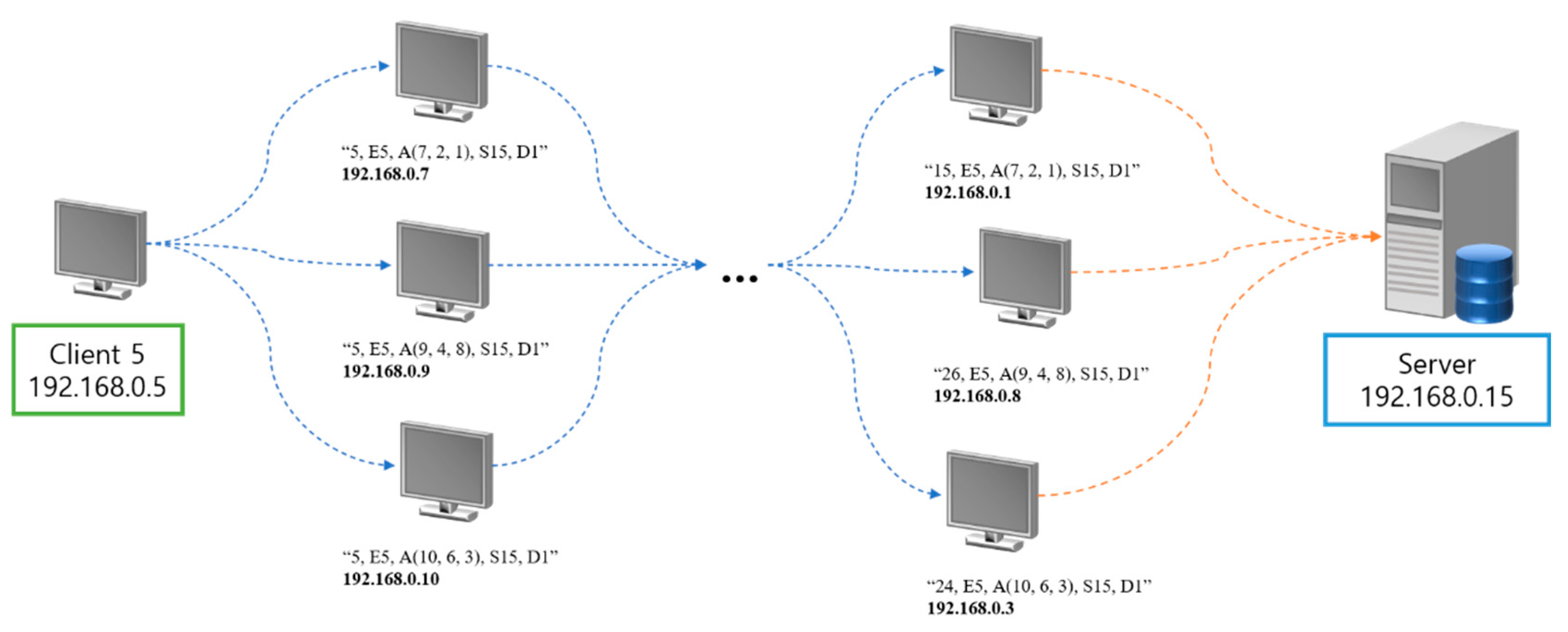
Figure 5 shows an example of how a client where an event occurred transmits a packet to the server. This figure shows a case in which an event occurred in Client 5. Let us assume that the three packets, which this client will transmit to other clients, are as follows:
- -
- packet 1: “5, E5, A (7, 2, 1), S15, D1”
- -
- packet 2: “5, E5, A (9, 4, 8), S15, D1”
- -
- packet 3: “5, E5, A (10, 6, 3), S15, D1”
These packets were generated because an event occurred in Client 5 (a = 5 in this case). Client 5 transmits packet 1 to a client of which the IP address’ octet 4 value is 7, packet 2 to a client of which the IP address’ octet 4 value is 9, and packet 3 to a client the IP address’ octet 4 value is 10.
Packet 1 passes through b = 7, c = 2, d = 1, which correspond to the value of octet 4 of the randomly generated client IP so that the Number of the packet transmitted to the server becomes n = a + b + c + d = 5 + 7 + 2 + 1 = 15 and the packet received by the server becomes “15, E5, A (7, 2, 1), S15, D1”. Packet 2 passes through b = 9, c = 4, d = 8, which correspond to the value of octet 4 of the randomly generated client IP so that the Number of the packet transmitted to the server becomes n = a + b + c + d = 5 + 9 + 4 + 8 = 26 and the packet received by the server becomes “26, E5, A (9, 4, 8), S15, D1”. Packet 3 passes through b = 10, c = 6, d = 3, which corresponds to the value of octet 4 of the randomly generated client IP so that the Number of the packet transmitted to the server becomes “24, E5, A (10, 6, 3), S15, D1”. Because each of the three packets mentioned above have the same front part n = a + b + c + d and have the same sensor data, f = D1, it can be seen that they were transmitted normally.
If n = a + b + c + d is not valid in a packet due to hacking or other reasons, or sensor data “f” does not coincide, the packet is discarded. In addition, if the data in the packet other than octet 4 of the client IP do not match the packet received by the server, it will mean that the data have not been accurately transmitted. Therefore, this packet is also discarded.
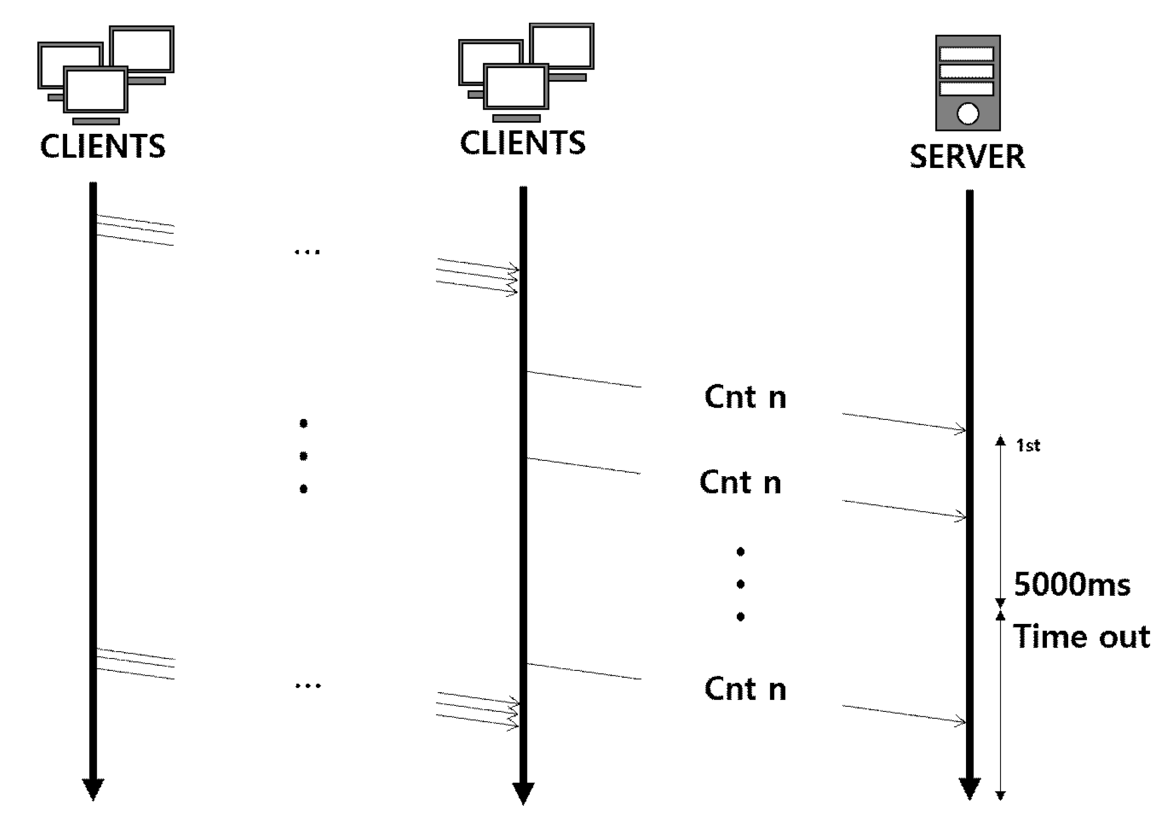
Figure 6 shows the timeout for the client data to be received by the server. The server waits up to 5000 ms (measured from the time the first data were received) for the data to arrive. This is to prevent the system from going down due to overload on the server or the client when the network is delayed or the amount of data to be transmitted is momentarily increased. This value of 5000 ms was determined to be the most suitable response delay time from the server through many experiments. Then, the data received are discarded, and the data received before the timeout are adopted after verification.
5. Proposed New AES-CBC Algorithm
This paper proposes a new AES-CBC algorithm suitable for the new IoT.
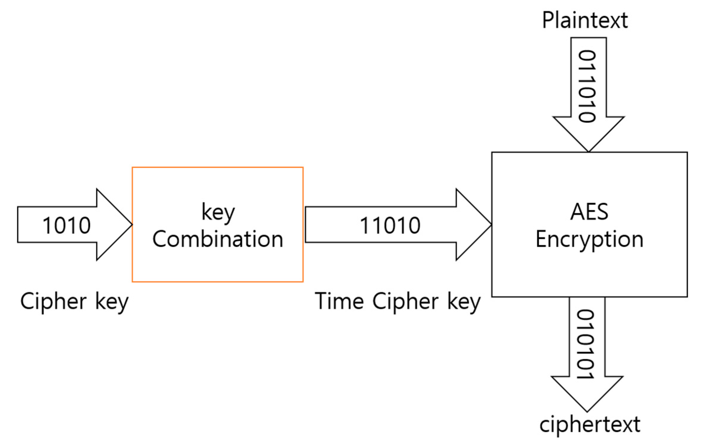
The conventional AES-CBC algorithm was set such that the cipher key was changed at regular intervals. In the process through which clients transmit data, encryption and decryption are sequentially performed while the data are transmitted to the server. That is, the data can be transmitted only when the cipher keys of all clients are identical, and the cipher keys are synchronized with the system time. When a new client has been registered, the cipher key used when a client has been added is configured to synchronize the cipher key. Figure 7 shows the overall structure of the encryption algorithm.
Two cipher keys should be used for encryption and decryption of the proposed algorithm: (the current cipher key) and (the cipher key in the immediately previous block). These cipher keys were identically set to 192 bits (24 bytes), and the initialization vector IV was set to 128 bits (16 bytes).
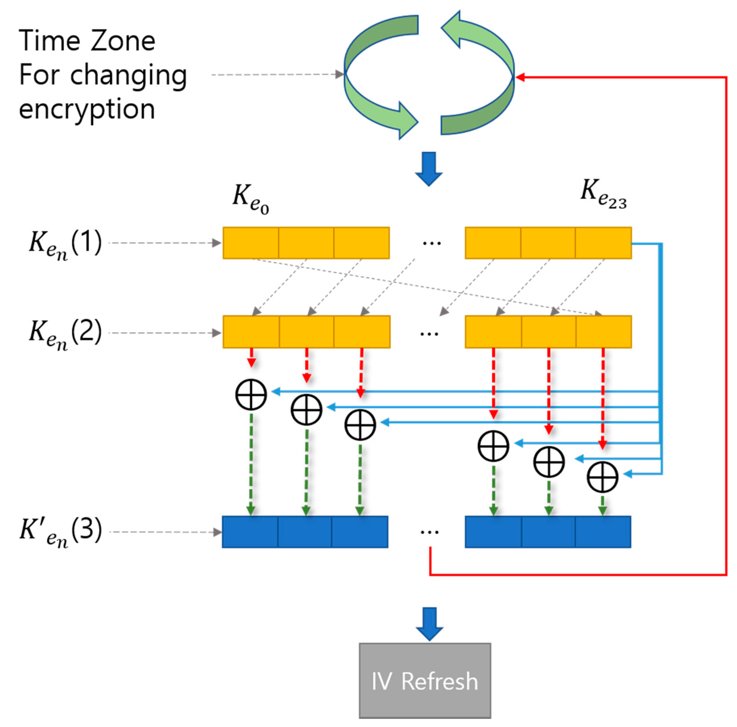
Figure 8 shows the process through which the cipher keys are changed. The cipher keys are changed at different time intervals. If the defined time is the same as the current time, the cipher key will not be changed and is used as it is; if the time is different, the cipher key will be changed. If the defined time and the current time are different, the cipher key is calculated by the time function and is output again.
In Figure 8, the process of changing the ciphertext is as follows.
[Step 1] Carry out shift operation of (1) to output (2), which is colored orange. Step 1 can be expressed as Equation (2).
[Step 2] Carry out XOR operations of (2) output in Step 1 with the value obtained by shifting (1) to the left bit by bit to output (3) which is colored blue. Step 2 can be expressed as Equation (3).
[Step 3] Change the new cipher key every minute using (3) and Time Zone for changing encryption.
“IV Refresh” in Figure 8 is a sort of initialization vector (IV) used in “CBC Operating mode.” Using “IV Refresh” is in the sense that the value of IV is changed every minute to enhance security further.
5.1. Time Zone
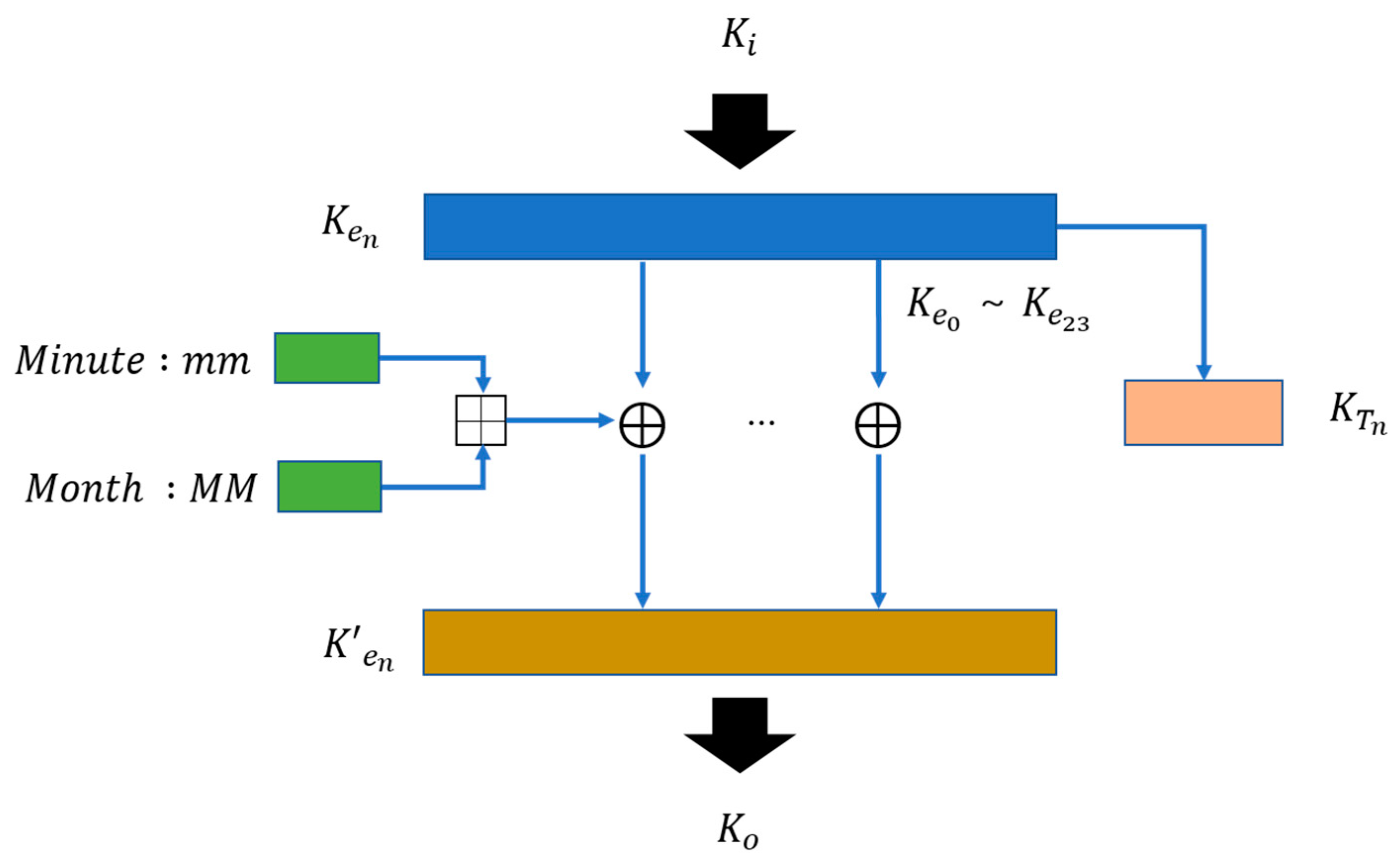
The cipher key changes when the defined time is not identical to the current time. Figure 9 shows the process through which cipher keys are generated. The month of the system’s current date and the minute of the current time are added. In this paper, months and minutes are used to generate cipher keys. If we use months, days, hours, and minutes simultaneously, cipher keys can become too complex and take a long time to decrypt. Using minutes instead of hours changes the cipher key every minute to enhance security.
The XOR operation is carried out for one byte of the 24 bytes of the input per time interval, in order, and the resultant values are fed to . Equation (4) describes the operation process:
In Equation (4), is the current cipher key, which is 192 bits, and (MM+mm) represents the month and minute, which is 8 bits. These two values are XOR operated to generate a new cipher key, .
The used here is copied to and stored there. is used as a temporary cipher key. It is used as the cipher key when decryption is not performed during network timeout or normal encryption/decryption. This cipher key is discarded when the next cipher key has been changed.
In Figure 9, is the current cipher key and represents the input, and is the new changed cipher key and represents the output.
5.2. Initialization Vector (IV) Change
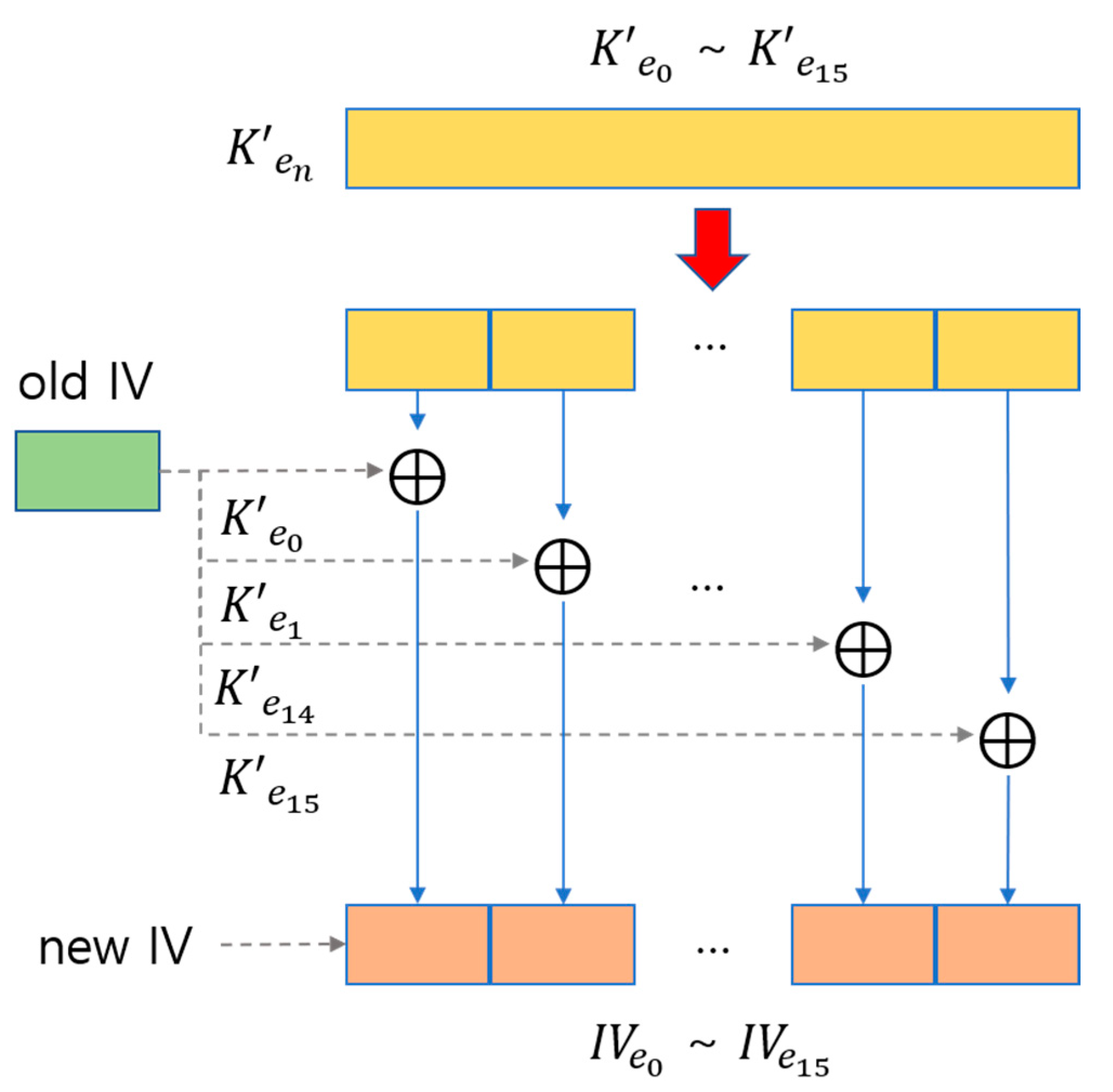
Figure 10 shows a diagram showing the process of changing IV. Of the 192 bits (24 bytes) of the cipher key the last eight bytes are discarded and only the first 16 bytes are used to carry out the XOR operation of
and IV. The calculated IV is used again to generate the cipher key.
6. System Configuration
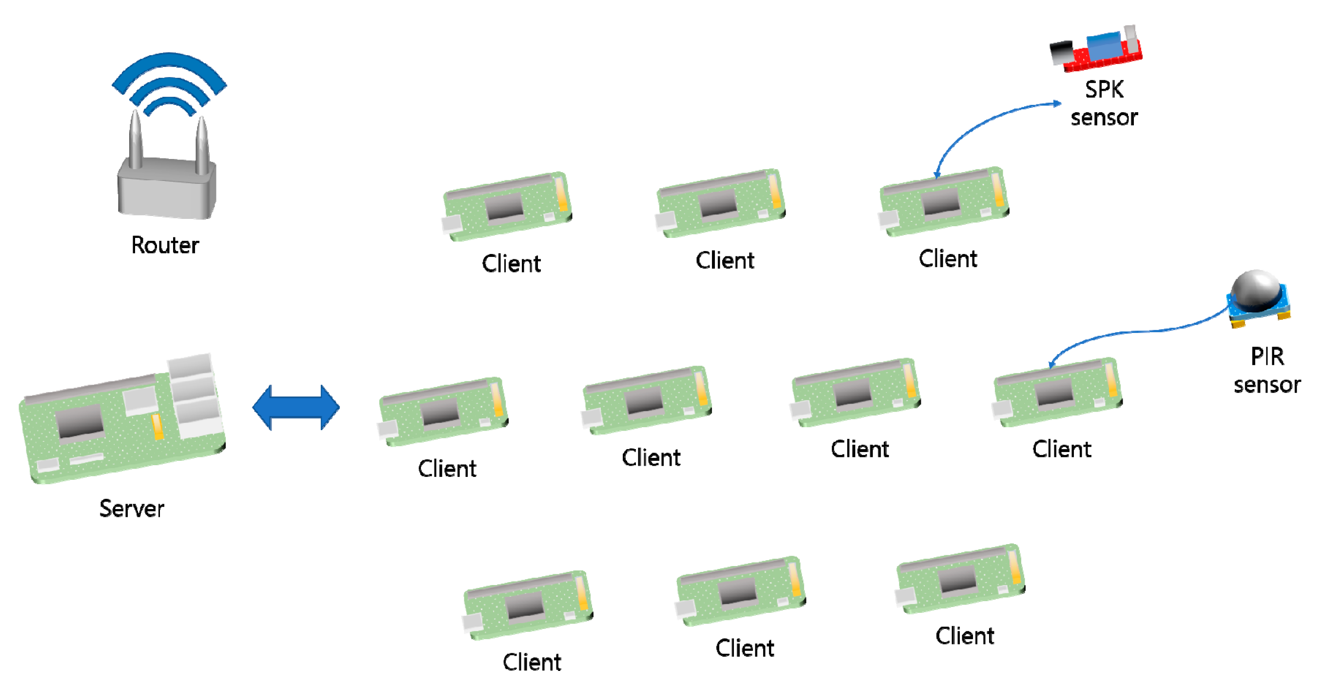
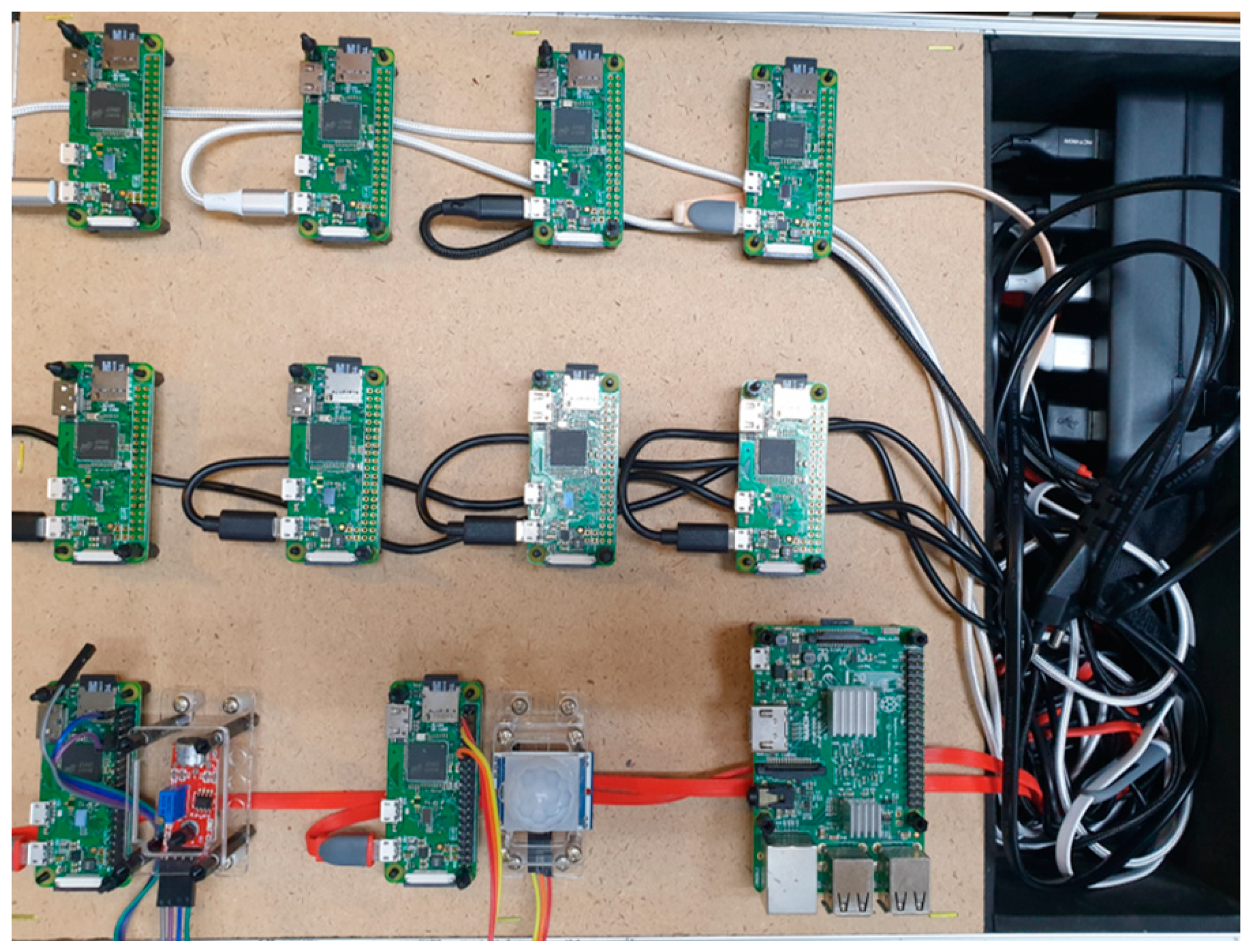
Figure 11 shows the hardware that makes up the system used for experimental testing of the algorithm. The left side of the picture shows the central server configured with one Raspberry Pi 3 B+ board, and the right side shows clients to which sensors were connected and configured using ten Raspberry Pi ZERO boards. The sensors consisted of speaker sensors and human-body-sensing sensors. The server and clients could communicate through a router. The clients encrypted the data generated by the sensors and transmitted the ciphertext to the central server through the other clients. The Raspberry Pi board used in the experiment was an experimental embedded board developed by the UK’s Raspberry Pi Foundation for basic computer science education. The specifications of the 3 B+ model used as a server are as follows: CPU ARM11 700 MHz, RAM 512 MB SDRAM, and GPU 250 MHz VideoCore IV. The specifications of the ZERO model are as follows: ARM11 1 GHz, RAM 512 MB SDRAM, and GPU 250 MHz video core IV.
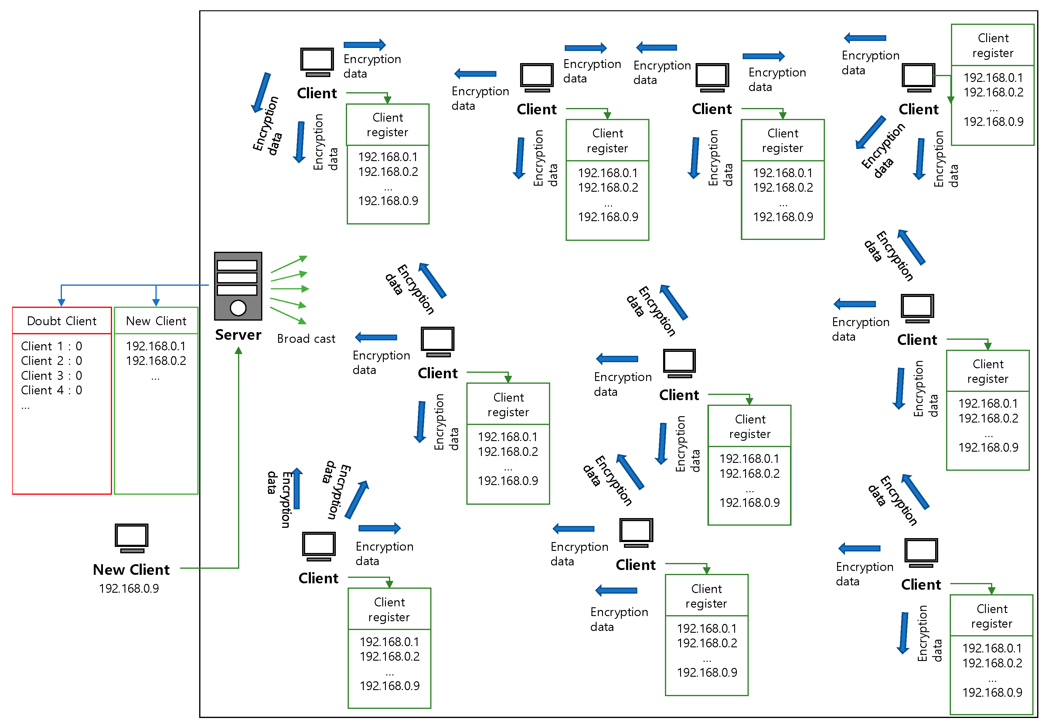
Figure 12 shows the overall structure of the system. The server stores suspicious clients and new clients in the lookup table, and each client has a lookup table that stores the addresses of newly entered clients. When a new client is registered through the server, the server transmits the newly entered client’s address to the connected clients through a broadcast. Each client stores the address received from the server in the lookup table. When an event occurs in the connected sensor, it creates the addresses of the clients to which it will transmit the data by referring to the lookup table.
6.1. Client Extension
When each new node (client) is created, the algorithm is not modified, but the internet protocol (IP) address of the new client is registered with the server, and the time is synchronized. When the client is added, the IP address of the newly added client is registered in the lookup table composed of text files subordinate to the server. When the client is registered, the server transmits information regarding the new client’s addition to other clients via broadcasting. Synchronized clients transmit data, including the client added, during the data transmission process. In the algorithm, the method of transmission between the server and the client is as shown below. The proposed algorithm is not optimized if there are fewer than 10 clients. Therefore, the transmission process is defined according to the number of clients, as shown in Algorithm 1.
When there are three or fewer clients, the data are sent directly to the server; when six or fewer clients are connected, the client where an event occurs transmits the data to three other clients, and the three clients transmit the data to the server for verification. In addition, when there are nine or fewer clients, the client transmits the data to two sets of three clients so that the data are verified twice, and when more than nine clients are connected, the data are sent to three sets of three clients so that the data are verified three times.
| Algorithm 1. Transmission method according to the number of clients |
| Number of times passed the client Cnt if Cnt <= 3 then Direct transfer to server Encrypt_Message else if Cnt <= 6 then while i < 3 do Encrypt_Message(.. A(n) ..) end while else if Cnt <= 9 then while i < 3 do Encrypt_Message(.. A(n, n) ..) end while else while i < 3 do Encrypt_Message(.. A(n, n, n) ..) end while end if |
6.2. Registration of Cases of Suspicious Clients
To enhance security, a method for disregarding suspicious clients was established. A lookup table was constructed on the server to determine whether the clients were problematic. The server determines the number of clients from which the data arrive at the server according to the total number of clients. The number of messages received by the server from a client when the number of clients is greater than six is determined, and when insufficient or incorrect data have been received, the relevant client is recorded in the lookup table. In this way, clients that could be problematic are determined using the accumulated data.
7. Experiment and Results
The tests were conducted to investigate the following cases.
- Handling of data by the data processing server when the client’s secret key is different.
- Handling of data transmitted from a wrong client.
- Dealing with several kinds of processing, such as the substitution of incorrect values into the data.
Figure 13 shows the experimental setup implemented for encryption and decryption. Two out of ten Raspberry Pi zero boards were used to configure the sensors. The sensors were a passive infrared sensor (PIR) sensor and a sound sensor. The PIR sensor was used to transmit signals when a human body was detected, and the sound sensor was used to send signals when a certain sound level (decibels) was reached.
7.1. Encryption and Decryption Analysis
Several experiments were conducted to observe whether encryption and decryption were carried out.
To proceed with the experiments, the equipment was configured as shown in Figure 13. Here, because there were 10 clients, the client where the event occurred sent encrypted data to three clients for data verification, which was repeated three times when the data were transmitted to the server. The IP addresses of the 10 clients became “192.168.0.N,” where N was the value of octet 4 for client, “5–14.” In the server address, the digit corresponding to the value of octet 4 for client was set as “15.” A client with “192.168.0.5” was connected to a PIR sensor, and a client with “192.168.0.6” was connected to a speaker sensor.
In the system, the cipher key was changed once per minute. When changed, the old cipher key was valid for 1 min. That is, the created cipher key could be used for 2 min, after which the cipher key was changed, and the old cipher key was discarded. The first experiment checked whether encryption/decryption was carried out properly.
The experiment was conducted by generating an event in the client connected to the PIR sensor. The client where the event occurred randomly generated IP addresses. The generated packet including the random data A (4, 2, 8) is “5, E5, A (4, 2, 8), S15, D1”. To enhance security, first, the random data of “A (4, 2, 8)” was encrypted by performing a left shift operation. Then, the entire packet “5, E5, A (4, 2, 8), S15, D1” was encrypted once more. The packet was encrypted because the data contained in the packet may be hacked due to a hacker, and the packet should be encrypted once more to enhance security. In this case, the keys used for the two encryptions are different. Using the same cipher key has the disadvantages that the structure of encryption and decryption is complex, encryption and decryption takes a long time, and energy consumption increases.
In this way, the client also generated two more packets such that the encrypted data were “5, E5, A (9, 7, 1), S15, D1” and “5, E5, A (3, 6, 10), S15, D1”. The three encrypted data packets were transmitted to the individual clients. The clients, corresponding to hosts 4, 9, and 3, decrypted the packet. In the decrypted packets, the part corresponding to the client address was decrypted again and added to the digit of “N,” which was the first digit of the packet, to accumulate the value of octet 4 for client. Host packets were added in the same way such that the digits became “9, E5, A (4, 2, 8), S15, D1”, “14, E5, A (9, 7, 1), S15, D1”, and “8, E5, A (3, 6, 10), S15, D1”, respectively, in the three clients. Finally, the received packets were decrypted in the server, and the data were adopted.
Table 2 shows the results of encryption and decryption through experiment. From the upper left of the table, the host addresses “192.168.0.5–14” were defined. It can be seen that the ciphertexts were transmitted to the relevant clients and sequentially transmitted to the server. Table 3 shows the ciphertext received at the server. The client addresses and the received ciphertexts were checked. If there was no problem, the data received from the clients were gathered to determine the data. Consequently, it can be seen that the data “1” was transmitted.
The second experiment checked whether encryption/decryption was carried out properly when an incorrect secret key or other value was entered during the transmission process. The system was constructed identically to the first experiment. Three tests were conducted as part of the second experiment: changing the secret key, changing the data, and receiving data from an irrelevant client.
7.2. Changing the Secret Key
The secret key value of the client corresponding to “192.168.0.6” was changed, and the encryption/decryption and transmission of data were checked. During data transmission, the client corresponding to “192.168.0.6” could not decrypt the received data and could not transmit the data to the next client. The server waited for a packet from the client for 5 s and processed only the previously received data if it did not receive the packet.
7.3. Changing the Data
This experiment was conducted by randomly changing the data in the packets and transmitting them. The client corresponding to “192.168.0.5” decrypted the data received from the client where the event occurred, or another client changed “D1” in the packet data “5, E5, A (4, 2, 8), S15, D1” to a different value and transmitted the data to other clients or the server. While the data were transmitted, encryption and decryption were carried out without any problems. The server decrypted the data received from each client, and compared and analyzed the data. The server determined that the packet corresponding to the randomly generated client “192.168.0.6” was wrong, discarded this data, and recorded the client in the lookup table as a suspicious client.
7.4. Receiving Data from an Irrelevant Client
This experiment was conducted using the same method as described above. The difference was that, although the server should have received packets such as “5, E5, A (3, 6, 10), S15, D1” from the client “192.168.0.10”, the packet was transmitted from an address in which the host address was not 10. In this way, the event of the client connected to the speaker sensor was generated approximately 100 times, and the condition of the server was checked.
Table 4 shows the number of data received from clients. In Table 4, c5 is the client to which the sensor was connected, and c14 is the client for experimentation. The client address was changed and transmission was performed. Three packets were generated by the client where the event occurred, and these were transmitted to other clients. One packet contained three client addresses. In the normal condition, if an event occurs 100 times, each client transmits and receives 100 times, resulting in a total of 900 transmissions and receptions for all clients. However, because the original address of the client corresponding to c14 was not used in this experiment, the total number of transmissions and receptions for each client was 600.
Accordingly, it can be confirmed that the server did not process the packets corresponding to client c14.
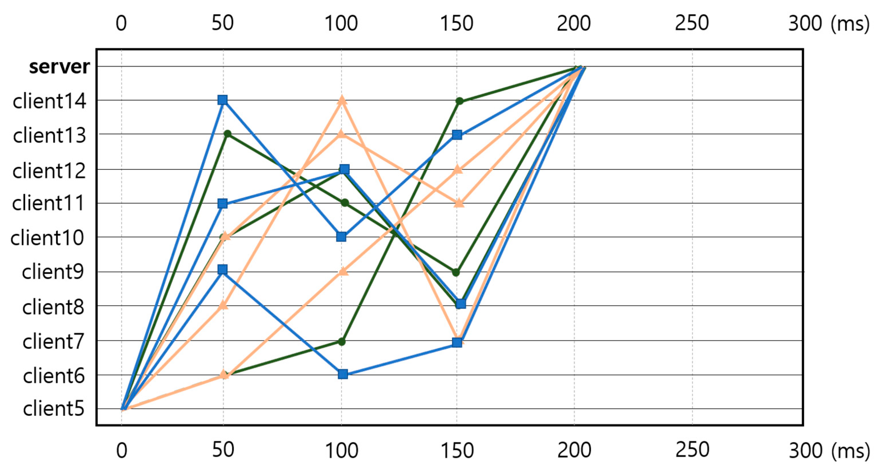
7.5. Communication Speed
Figure 14 shows a graph of three measurements of the transmission speeds from the clients to the server. The first communications are marked with squares, the second with triangles, and the third with circles. The delays were generally 50 ms, and a cumulative average delay of approximately 200 ms was measured. The round-trip time (RTT) of the wirelessly connected router network had a minimum delay of 43 ms, a maximum delay of 632 ms, and an average of 75 ms. When the averages of the encryption/decryption times were added, the average delay was found to be approximately 80 ms.
7.6. Analysis of the Proposed Aes-Cbc Algorithm for Time and Power Consumption
Overhead refers to the additional memory required to process an instruction. The causes of overhead include high-priority processing first, the use of a stack frame of an external function, and increases in signal data to ensure network communication.
To calculate the overhead, in this study, 100 events were generated in the client and the quantity of resources (time, power, and packet) of each node were measured. This enabled the identification of the quantities of resources generated by encryption and decryption excluding network delays.
Table 5 shows the minimum, average, and maximum values (overhead) of the time taken and power consumed by each node during encryption and decryption when an event occurred in the client.
To calculate the power, an oscilloscope and ammeter were used. We measured the voltage using the oscilloscope’s trigger function because the voltage rises instantaneously when sending data. The current was measured with an ammeter, and power was calculated by multiplying the measured voltage by the current flowing through the client. At this time, the measured voltage and current were effective values. In our experimental system, one Raspberry Pi board was implemented as a client.
When the AES-CBC algorithm proposed in this paper was used, the packet size increased from 27 bytes on average (maximum 31 bytes) before encryption to 49 bytes on average (maximum 57 bytes) after encryption. If a TCP/IP protocol packet was included here, the size of the packet increased to 89 bytes (maximum 97 bytes). However, given the maximum transmission unit (MTU) of IPv4, the increase in size of a packet due to encryption and the TCP/IP protocol does not affect network reliability. In general, protocol packets are referred to as network packet overhead.
8. Comparison with Conventional AES-CBC Algorithm
The time taken and the amount of power consumed for encryption and decryption by the conventional AES-CBC algorithm [20] and those by the proposed AES-CBC were compared. In the experiment, 100 events were generated in the client, and the average values of packet size, time taken, and amount of power consumed for encryption and decryption were compared.
The average size of packets encrypted in the conventional AES-CBC algorithm was 51 bytes, and 91 bytes including the protocol packet. By comparison, the average size of packets encrypted in the proposed AES-CBC algorithm was 49 bytes, and 89 bytes including the protocol packet.
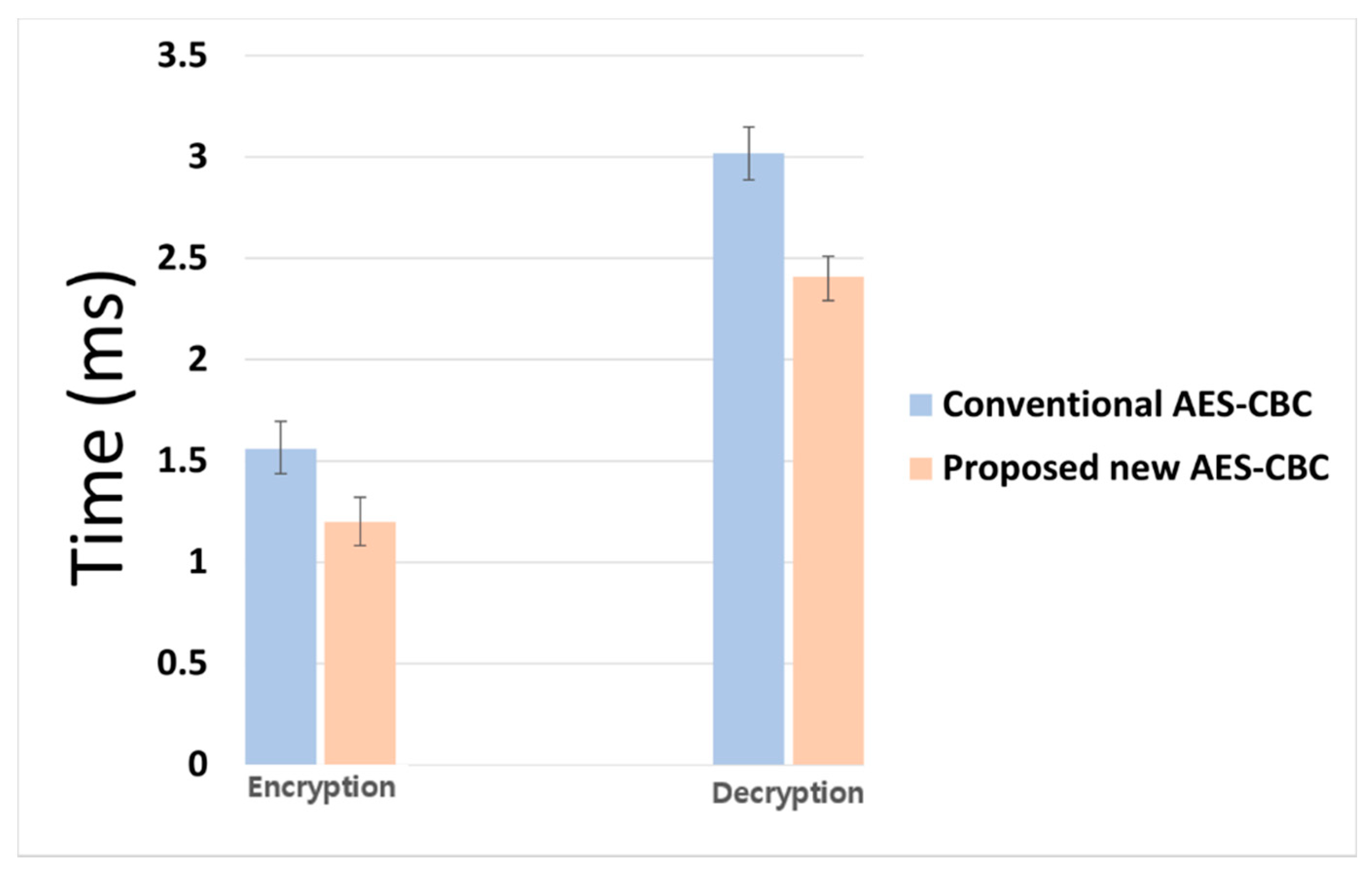
Figure 15 shows the comparison of the times taken for encryption and decryption by the conventional AES-CBC algorithm and by the proposed AES-CBC algorithm. Table 6 shows the mean value, minimum value, maximum value, and standard deviation of the time spent for encryption and decryption as numerical values. In the case of the conventional AES-CBC algorithm, the average time taken for encryption was 1.56 ms, and the average time taken for decryption was 3.02 ms. By comparison, in the case of the proposed AES-CBC algorithm, the average time taken for encryption time 1.2 ms and the average time taken for decryption time 2.41 ms, a decrease of about 20–23%.
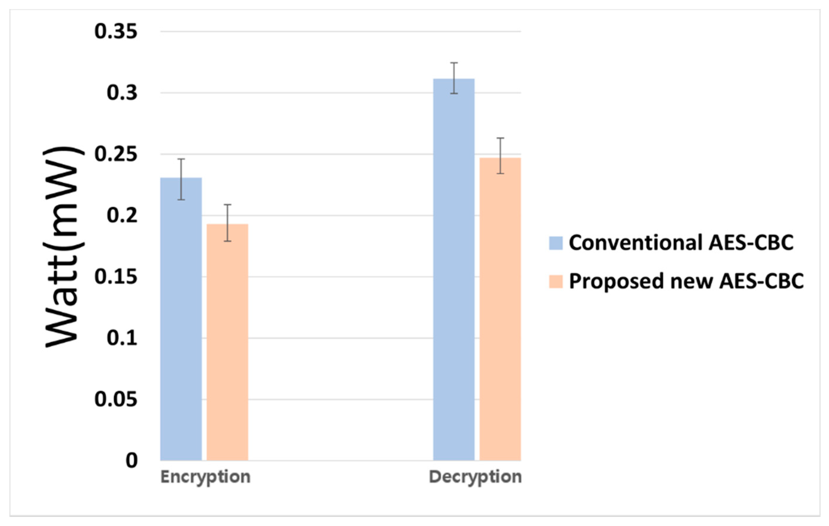
Figure 16 shows the amount of power consumed for encryption and decryption by the conventional AES-CBC algorithm and the proposed AES-CBC algorithm. Table 7 shows the mean value, minimum value, maximum value, and standard deviation of the power consumed for encryption and decryption as numerical values. In the case of the conventional AES-CBC algorithm, the average amount of power consumed for encryption was 0.231 mW, and that for decryption was 0.311 mW. By comparison, in the case of the proposed AES-CBC algorithm, the average amount of power consumed for encryption was 0.193 mW and that for decryption was 0.247 mW, representing a decrease of approximately 17–21%.
9. Conclusions
In this paper, we simplified the conventional DAG-based blockchain structure and proposed a new AES-CBC algorithm with enhanced security by periodically changing the secret key and initialization vector (IV) in the conventional AES-CBC encryption algorithm. In the proposed new algorithm, the key is renewed every minute, and when a client event has occurred, the host addresses of the clients connected to the network are randomly set to create three ciphertexts, and the ciphertexts are transmitted to the clients. The transmission process depends on the number of clients, and the transmitted ciphertexts are transmitted to the server through other clients. Regarding server and client information, new client host addresses were created by referring to individual lookup tables, and a database for storing problematic clients was configured in the server’s lookup table. Clients were identified as suspicious in cases when the server did not receive messages from the clients, and in cases in which the client address corresponding to the encrypted packet was not identical to the address of the client that transmitted the packet. When a new client was registered, the server provided information about the new client through a broadcast. In this way, the proposed new algorithm was improved to apply to the IoT because its security is better than that of conventional algorithms.
Through experiments, it was found that the new AES-CBC algorithm proposed in this paper reduces the time taken and the amount of power consumed for encryption and decryption by approximately 20% compared to the conventional AES-CBC algorithm.
In the future, we plan to build a database with an algorithm that can be practically used and build a system to improve communication and security.
Author Contributions
Conceptualization, S.-W.L. and K.-B.S.; methodology, S.-W.L. and K.-B.S.; software, S.-W.L.; validation, S.-W.L. and K.-B.S.; formal analysis, S.-W.L. and K.-B.S.; investigation, S.-W.L. and K.-B.S.; resources, S.-W.L.; data curation, S.-W.L.; writing—original draft preparation, S.-W.L.; writing—review and editing, K.-B.S.; visualization, S.-W.L. and K.-B.S.; supervision, K.-B.S.; project administration, K.-B.S.; All authors have read and agreed to the published version of the manuscript.
Funding
This research received no external funding.
Conflicts of Interest
The authors declare no conflict of interest.
References
- Dorri, A.; Kanhere, S.S.; Jurdak, R. Towards an Optimized BlockChain for IoT. In Proceedings of the 2017 IEEE/ACM Second International Conference on Internet-of-Things Design and Implementation (IoTDI), Pittsburgh, PA, USA, 18–21 June 2017. [Google Scholar]
- Wang, Q.; Zhu, X.; Ni, Y.; Gu, L.; Zhu, H. Blockchain for the IoT and industrial IoT: A review. Internet Things Vol. 2020, 10, 100081. [Google Scholar] [CrossRef]
- Li, C.; Zhang, Y.; Xie, Y. When an attacker meets a cipher-image in 2018: A year in review. J. Inform. Secur. Appl. 2019, 48, 102361. [Google Scholar] [CrossRef] [Green Version]
- Zhou, L.; Tan, F.; Yu, F. A Robust Synchronization-Based Chaotic Secure Communication Scheme with Double-Layered and Multiple Hybrid Networks. IEEE Syst. J. 2020, 14, 2508–2519. [Google Scholar] [CrossRef]
- Kietzmann, P.; Boeckmann, L.; Lanzieri, L.; Schmidt, C.T.; Wahlisch, M. A Performance Study of Crypto-Hardware in the Low-end IoT. In Proceedings of the International Conference on Embedded Wireless Systems and Networks (EWSN), Lyon, France, 6–13 February 2021. [Google Scholar]
- Mokhov, S.A. Towards Security Hardening of Scientific Demand-Driven and Pipelined Distributed Computing Systems. In Proceedings of the 2008 International Symposium on Parallel and Distributed Computing, Krakow, Poland, 1–5 July 2008. [Google Scholar]
- Aileni, R.M.; Suciu, G. IoMT: A blockchain perspective. Decent. Internet Things 2020, 71, 199–215. [Google Scholar]
- Elsayeh, M.; Ezzat, K.A.; El-Nashar, H.; Omran, L.N. Cybersecurity Architecture for the Internet of Medical Things and Connected Devices Using Blockchain. Biomed. Eng. Appl. Basis Commun. 2021, 33, 2150013. [Google Scholar] [CrossRef]
- Dorri, A.; Kanhere, S.S.; Jurdak, R.; Gauravaram, P. LSB: A Lightweight Scalable Blockchain for IoT security and anonymity. J. Parallel Distrib. Comput. 2019, 134, 180–197. [Google Scholar] [CrossRef]
- Rao, A.R.; Clarke, D. Perspectives on emerging directions in using IoT devices in blockchain applications. Internet Things J. 2019, 10, 100079. [Google Scholar] [CrossRef]
- Alghayadh, F.; Debnath, D. A Hybrid Intrusion Detection System for Smart Home Security. In Proceedings of the 2020 IEEE International Conference on Electro Information Technology (EIT), Chicago, IL, USA, 31 July–1 August 2020; pp. 319–323. [Google Scholar]
- Chatterjee, R.; Chakraborty, R. A Modified Lightweight PRESENT Cipher For IoT Security. In Proceedings of the 2020 International Conference on Computer Science, Engineering and Applications (ICCSEA), Gunupur, India, 13–14 March 2020; pp. 1–6. [Google Scholar]
- Dorri, A.; Kanhere, S.S.; Jurdak, R.; Gauravaram, P. Blockchain for IoT security and privacy: The case study of a smart home. In Proceedings of the IEEE Annual Conference on Pervasive Computing and Communications Workshops (PerCom), Kona, HI, USA, 13–17 March 2017; pp. 618–623. [Google Scholar]
- Tanwar, S.; Patel, P.; Patel, K.; Tyagi, S.; Kumar, N.; Obaidat, S. An advanced Internet of Thing based Security Alert System for Smart Home. In Proceedings of the 2017 International Conference on Computer, Information and Telecommunication Systems (CITS), Dalian, China, 21–23 July 2017; pp. 25–29. [Google Scholar]
- Geneiatakis, D.; Kounelis, I.; Neisse, R.; Nai-Fovino, I.; Steri, G.; Baldini, G. Security and privacy issues for an IoT based smart home. In Proceedings of the 2017 40th International Convention on Information and Communication Technology, Electronics and Microelectronics (MIPRO), Opatija, Croatia, 22–26 May 2017; pp. 1292–1297. [Google Scholar]
- Biswas, S.; Sharif, K.; Li, F.; Maharjan, S.; Mohanty, S.P.; Wang, Y. PoBT: A Lightweight Consensus Algorithm for Scalable IoT Business Blockchain. IEEE Internet Things J. 2019, 7, 2343–2355. [Google Scholar] [CrossRef]
- Mohanty, S.N.; Ramya, K.C.; Rani, S.S.; Gupta, D.; Shankar, K.; Lakshmanaprabu, S.K.; Khanna, A. An efficient Lightweight integrated Blockchain (ELIB) model for IoT security and privacy. Future Gener. Comput. Syst. 2020, 102, 1027–1037. [Google Scholar] [CrossRef]
- Huang, J.; Kong, L.; Chen, G.; Wu, M.Y.; Liu, X.; Zeng, P. Towards Secure Industrial IoT: Blockchain System With Credit-Based Consensus Mechanism. IEEE Trans. Ind. Inform. 2019, 15, 3680–3689. [Google Scholar] [CrossRef]
- Pervez, H.; Muneeb, M.; Irfan, M.U.; Heq, I.U. A Comparative Analysis of DAG-Based Blockchain Architectures. In Proceedings of the International Conference on Open Source Systems and Technologies (ICOSST), Lahore, Pakistan, 19–21 December 2018; pp. 27–34. [Google Scholar]
- Cui, L.; Yang, S.; Chen, Z.; Pan, Y.; Xu, M.; Xu, K. An Efficient and Compacted DAG-Based Blockchain Protocol for Industrial Internet of Things. IEEE Trans. Ind. Inform. 2020, 16, 4134–4145. [Google Scholar] [CrossRef]
- Zhou, T.; Li, X.; Zhao, H. DLattice: A Permission-Less Blockchain Based on DPoS-BA-DAG Consensus for Data Tokenization. IEEE Access 2019, 7, 39273–39287. [Google Scholar] [CrossRef]
- Yang, S.; Chen, Z.; Cui, L.; Xu, M.; Ming, Z.; Xu, K. CoDAG: An Efficient and Compacted DAG-Based Blockchain Protocol. In Proceedings of the IEEE International Conference on Blockchain (Blockchain), Atlanta, GA, USA, 14–17 July 2019; pp. 314–318. [Google Scholar]
- Watanabe, H.; Ishida, T.; Ohashi, S.; Fujimura, S.; Nakadaira, A.; Hidaka, K.; Kishigami, J. Enhancing Blockchain Traceability with DAG-Based Tokens. In Proceedings of the IEEE International Conference on Blockchain (Blockchain), Atlanta, GA, USA, 14–17 July 2019; pp. 220–227. [Google Scholar]
- Vaidehi, M.; Rabi, B.J. Design and analysis of AES-CBC mode for high security applications. In Proceedings of the International Conference on Current Trends in Engineering and Technology (ICCTET), Coimbatore, India, 8 July 2014. [Google Scholar]
- William, F.E.; Carl, H.W.M.; John, L.S.; Walter, L. Tuchman. Message Verification and Transmission Error Detection by Block Chaining. U.S. Patent 4,074,066, 14 February 1978. [Google Scholar]
- Tan, C.; Deng, X.; Zhang, L. Identification of Block Ciphers under CBC Mode. Procedia Comput. Sci. 2018, 131, 65–71. [Google Scholar] [CrossRef]
- Abidi, A.; Guyeux, C.; Bouallegue, B.; Machhout, M. Conditions to Have a Well-Disordered Dynamics in the CBC Mode of Operation. In Proceedings of the 2017 IEEE/ACS 14th International Conference on Computer Systems and Applications (AICCSA), Hammamet, Tunisia, 30 October–3 November 2017; Volume 1, pp. 226–231. [Google Scholar]
Figure 1.
Structure of Directed Acyclic Graph (DAG).

Figure 2.
Structure of Substitution–Permutation Network (SPN).

Figure 3.
Block Diagram of Cipher Block Chaining operating mode (CBC), (a) Encryption process, (b) Decryption process [25].
Figure 3.
Block Diagram of Cipher Block Chaining operating mode (CBC), (a) Encryption process, (b) Decryption process [25].

Figure 4.
Structure of the simplified DAG-based blockchain.

Figure 5.
Process through which data are transmitted from clients to the server.

Figure 6.
Diagram of the timeout for the client data to be received by the server.

Figure 7.
Overall structure of the encryption algorithm.

Figure 8.
Process through which the cipher keys are changed.

Figure 9.
Process through which cipher keys are generated.

Figure 10.
Diagram showing the process of changing IV.

Figure 11.
Hardware equipment that composes the system.

Figure 12.
Overall structure of the system.

Figure 13.
Experimental setup implemented for encryption and decryption.

Figure 14.
Transmission speeds from the clients to the server.

Figure 15.
Average time taken during encryption and decryption in conventional AES-CBC and proposed AES-CBC algorithms.
Figure 15.
Average time taken during encryption and decryption in conventional AES-CBC and proposed AES-CBC algorithms.

Figure 16.
Average power consumption during encryption and decryption in conventional AES-CBC and proposed AES-CBC algorithms.
Figure 16.
Average power consumption during encryption and decryption in conventional AES-CBC and proposed AES-CBC algorithms.


Table 1.
Packet structure transmitted when an event has occurred.
| Number | Event Client Address | Encryption | Server Address | Sensor Data | ||
|---|---|---|---|---|---|---|
| Random Address 1 | Random Address 2 | Random Address 3 | ||||
| n | a | b | c | d | e | f |
| Packet structure: “n, Ea, A (b, c, d), Se, Df” | ||||||
Table 2.
Results of encryption and decryption through experiment (value of octet 4 for client 5–14).
Table 2.
Results of encryption and decryption through experiment (value of octet 4 for client 5–14).
| Client IP | Ciphertext after Encryption | Packet after Decryption |
|---|---|---|
| 192.168.0.5 | st1: 51 42 1a 8a 4f ed 18 c8 91 ae 42 92 81 92 c8 c9 fa d2 | st1: “5, E5, A(6, 9, 8), S15, D1” |
| st2: 10 ef 4f 16 45 9a d7 8f ff fe 1a 71 8e 79 fb e4 e2 6a | st2: “5, E5, A(13, 14, 7), S15, D1” | |
| st3: 8c 67 ea af b1 2f 3d 78 f 1f 44 7e 75 87 32 5e 9c 29 | st3: “5, E5, A(10, 12, 11), S15, D1” | |
| 192.168.0.6 | 51 42 1a 8a 4f ed 18 c8 91 ae 42 92 81 92 c8 c9 fa d2 | “11, E5, A(6, 9, 8), S15, D1” |
| 192.168.0.7 | 93 1b 7e 14 c3 84 c7 ec 25 cb f3 c6 23 c4 bd e9 83 4d | “39, E5, A(13, 14 7), S15, D1” |
| 192.168.0.8 | 43 ab 9a 73 dl 64 6b c8 a 87 1a 53 6e 22 b2 a8 db e1 | “28, E5, A(6, 9, 8), S15, D1” |
| 192.168.0.9 | 9c 69 15 3e f fa 24 5e f7 e2 3d d5 a0 e a 66 93 b3 | “20, E5, A(6, 9, 8), S15, D1” |
| 192.168.0.10 | 8c 67 ea af b1 2f 3d 78 f 1f 44 7e 75 87 32 5c 9c 29 | “15, E5, A(10, 12, 11), S15, D1” |
| 192.168.0.11 | 75 79 c6 5a 24 96 32 36 7b 3b 61 48 d3 53 16 24 41 6e | “38, E5, A(10, 12, 11), S15, D1” |
| 192.168.0.12 | da 1a b0 15 d1 81 ae db 85 94 70 8c 2 27 d8 87 43 57 | “27, E5, A(10, 12, 11), S15, D1” |
| 192.168.0.13 | 10 ef 4f 16 45 9a d7 8f ff fe 1a 71 8e 79 fb e4 e2 6a | “18, E5, A(13, 14, 7), S15, D1” |
| 192.168.0.14 | 21 68 1a 79 7d 22 b6 bb 71 7c 14 d4 26 bf 3c f2 8d 4 | “32, E5, A(13, 14, 7), S15, D1” |
Table 3.
Ciphertext received from the client.
| Client IP | Ciphertext after Encryption | Data |
|---|---|---|
| 192.168.0.8 | ff 30 6d f 9f 8a c0 33 d2 68 67 18 e7 93 b6 12 c5 54 | 1 |
| 192.168.0.7 | 85 62 a2 d9 b1 82 f5 1e 42 f4 a9 d2 9c 99 e9 7c 95 11 | 1 |
| 192.168.0.12 | 17 b1 34 c3 43 7d 16 ab 3c 96 85 c2 cf c1 1a 29 ea 21 | 1 |
Table 4.
Number of data received from clients.
| Number of Data Received | ||||||||||
|---|---|---|---|---|---|---|---|---|---|---|
| Client | c5 | c6 | c7 | c8 | c9 | c10 | c11 | c12 | c13 | c14 |
| Number | Event | 79 | 72 | 90 | 69 | 63 | 77 | 66 | 84 | 0 |
Table 5.
Time and power consumption during encryption and decryption.
| Time (ms) | Power Consumption (mW) | |||||
|---|---|---|---|---|---|---|
| Minimum | Average | Maximum (Overhead) | Minimum | Average | Maximum (Overhead) | |
| Encryption | 1.42 | 1.56 | 2.35 | 0.196 | 0.22 | 0.262 |
| Decryption | 1.33 | 1.38 | 2.89 | 0.243 | 0.282 | 0.375 |
Table 6.
Average time taken and its standard deviation during encryption and decryption.
| Time (ms) | ||||||||
|---|---|---|---|---|---|---|---|---|
| Encryption | Decryption | |||||||
| Average | Min | Max | Standard Deviation | Average | Min | Max | Standard Deviation | |
| Conventional AES-CBC | 1.56 | 1.43 | 1.69 | 0.058 | 3.02 | 2.91 | 3.14 | 0.049 |
| Proposed new AES-CBC | 1.2 | 1.08 | 1.35 | 0.057 | 2.41 | 2.3 | 2.52 | 0.047 |
Table 7.
Average power consumption and standard deviation during encryption and decryption.
| Watt (mW) | ||||||||
|---|---|---|---|---|---|---|---|---|
| Encryption | Decryption | |||||||
| Average | Min | Max | Standard Deviation | Average | Min | Max | Standard Deviation | |
| Conventional AES-CBC | 0.231 | 0.213 | 0.246 | 0.0111 | 0.311 | 0.299 | 0.324 | 0.0106 |
| Proposed new AES-CBC | 0.193 | 0.179 | 0.209 | 0.0107 | 0.247 | 0.234 | 0.263 | 0.0104 |
Publisher’s Note: MDPI stays neutral with regard to jurisdictional claims in published maps and institutional affiliations. |
© 2021 by the authors. Licensee MDPI, Basel, Switzerland. This article is an open access article distributed under the terms and conditions of the Creative Commons Attribution (CC BY) license (https://creativecommons.org/licenses/by/4.0/).
Share and Cite
MDPI and ACS Style
Lee, S.-W.; Sim, K.-B. Design and Hardware Implementation of a Simplified DAG-Based Blockchain and New AES-CBC Algorithm for IoT Security. Electronics 2021, 10, 1127. https://0-doi-org.brum.beds.ac.uk/10.3390/electronics10091127
AMA Style
Lee S-W, Sim K-B. Design and Hardware Implementation of a Simplified DAG-Based Blockchain and New AES-CBC Algorithm for IoT Security. Electronics. 2021; 10(9):1127. https://0-doi-org.brum.beds.ac.uk/10.3390/electronics10091127
Chicago/Turabian StyleLee, Sung-Won, and Kwee-Bo Sim. 2021. "Design and Hardware Implementation of a Simplified DAG-Based Blockchain and New AES-CBC Algorithm for IoT Security" Electronics 10, no. 9: 1127. https://0-doi-org.brum.beds.ac.uk/10.3390/electronics10091127
Note that from the first issue of 2016, this journal uses article numbers instead of page numbers. See further details here.