
A Novel Hybrid Active Power Filter with Multi-Coupled Coils
by
 , , , ,
Gang Xue
 ,
,
Baichao Chen
*,
Cuihua Tian
,
Jiaxin Yuan
,
Yuxiong Zhou
,
Guanru Chen
,
Yao Luo
and
Yaojun Chen
School of Electrical Engineering and Automation, Wuhan University, Wuhan 430072, China
*
Author to whom correspondence should be addressed.
Electronics 2021, 10(9), 998; https://0-doi-org.brum.beds.ac.uk/10.3390/electronics10090998
Submission received: 23 March 2021
/
Revised: 17 April 2021
/
Accepted: 20 April 2021
/
Published: 22 April 2021
(This article belongs to the Section Power Electronics)
Abstract
:This paper proposes a hybrid active power filter (HAPF) with multi-coupled coils, applied to a medium- and high-voltage power grid. The passive filter of the proposed HAPF adopts the structure of multi-coupled coils to compress the traditional multiple LC branches into one branch which presents the same harmonic impedance characteristics as the former multiple LC branches. In the active power filter of the HAPF, a coupled inductor, instead of a transformer, is used to connect with the passive filter. The coupled inductor has mutual inductances with inductors of the passive filter. Through spatial magnetic coupling, the active power filter can inject compensation current into the power grid to eliminate the residual harmonics and absorb active power from the power grid to maintain the DC capacitor voltage. When the active power filter is open-circuited or short-circuited, the filtering effect of the passive filter can still be guaranteed, which improves the reliability of the filter. The benefits of the proposed HAPF with excellent harmonic filtering performance are that the inductors occupy only 1/3 space as compared with traditional three-tuned LC filter, and very small power of the active power filter. The feasibility of the proposed HAPF is verified through simulations and experiment.
1. Introduction
In the power grid, nonlinear loads result in harmonic problems: increasing the power loss in the power system, interfering with the communication network, affecting the performance of high-precision devices, etc. [1,2].
The power filter is usually used to deal with harmonic problems in the power system, which can be classified as passive filter (PF), active power filter (APF), and hybrid active power filter (HAPF). PF is widely used in the power grid because of its simple structure, low cost, and mature technology [3,4,5]. However, the filtering effect of PF depends on its own element parameters and the grid parameters. Besides, PF usually has large volume, large required space. Compared with PF, the filtering effect of APF is not affected by grid parameters and the control of APF is flexible [6,7,8]. However, standalone APF has limited capacity and high cost, which is not suitable for high-voltage and a large-capacity situation.
In order to combine the advantages of both PF (large capacity, high reliability) and APF (excellent control performance), HAPFs of various topologies were proposed, which can reduce the capacity of active power filter in the medium- and high-voltage power grid [9,10,11,12,13,14,15,16,17,18,19,20,21,22]. There are two types of HAPFs: series HAPFs and shunt HAPFs. In series HAPF, the active power filter is connected to the power grid in series using a transformer [9]. The series HAPF has good filtering performance, but the fundamental current flows through the transformer, limiting the feasibility of the practical application.
The common topologies of shunt HAPF can be divided into the following three types:
- (1)
- The active power filter that is in parallel with the passive filter [10,11]. In this type of topology, the active power filter is connected to the power grid through a transformer, whose volume is large. The topology is simple, but on the low-voltage side of the transformer, the current is relatively large. Besides, the output current of the active power filter may flow into the parallel PF.
- (2)
- The active power filter that is in series with the passive filter [12,13,14,15,16,17,18]. In this type of topology, the active power filter can be connected in series with the passive filter directly or through a transformer. The passive filter bears most of the fundamental voltage and the fundamental voltage of the active power filter is very small. Considering that the active power filter and the passive filter are in series, once the active power filter is open-circuited, the high fundamental voltage will be applied to the transformer winding.
- (3)
- The injection-type HAPF: the active power filter is shunted to a fundamental resonance circuit, through a matching transformer [19,20,21,22]. The injection-type HAPF can significantly reduce the fundamental voltage of the active power filter. However, the fundamental resonator has a large volume. In addition, an additional rectifier is needed to support the DC-side voltage.
The passive filter of HAPF is generally the LC filter, which is used to eliminate characteristic harmonics, such as 3rd, 5th, 7th, and 11th harmonics. Three inductors are needed for each phase to eliminate 5th, 7th, and 11th harmonics, so, for three phases, nine inductors are needed. These inductors are usually arranged separately (straight-line shape, triangle, etc.) to eliminate the effect of mutual inductances. Thus, these inductors would occupy a large area. The conventional dry-type air core reactor also has a stacking mode, but in order to eliminate mutual inductances and other reasons, the stacking mode will significantly raise the center of gravity of the reactor as a whole, increasing the requirements for the safety design of structural accessories.
Authors developed a new method for calculating the inductance of air-core circular coils with rectangular cross section and parallel axes [23,24]. Moreover, a compact multi-tuned filter with coupled inductors was proposed in [5], which can reduce the required space of inductors while eliminating characteristic harmonics. However, this structure still has other inherent problems of conventional passive filters (detuning, resonance, etc.).
Based on this, this paper proposes a novel hybrid active power filter (HAPF) with multi-coupled coils. The passive filter of the HAPF uses a multi-coupled coils structure, and the design method of the multi-coupled coils is the same as [5]. The active power filter of the HAPF includes an active converter and a coupled inductor. Mutual inductances exist between the coupled inductor and each coil of the passive filter. The active power filter is connected with the passive filter through the coupled inductor.
In hybrid compensation, the converter generates a current on the coupled inductor. Then, this output current will be injected into the passive filter branch through spatial magnetic coupling to eliminate the residual harmonics. At the same time, the active converter would absorb the active power from the grid to maintain the DC capacitor voltage. The coupled inductor of the active power filter is closest to the main coil of the passive filter, which can obtain a high coupling coefficient.
The proposed HAPF topology in this paper has two distinct innovations:
- (1)
- The multi-coupled coils used in the passive filter of the HAPF compress the traditional multiple LC branches into one branch which presents the same harmonic impedance characteristics as the former multiple LC branches. The inductors occupy only 1/3 of the space as compared with the traditional three-tuned LC filter.
- (2)
- A coupled inductor, instead of a transformer, is used in the active power filter of the HAPF to connect with the passive filter. When the active power filter is open-circuited or short-circuited (even if the protection does not work and not cut off from the active power filter), the filtering effect of the passive filter can still be guaranteed. The capacity of the active power filter in the proposed HAPF is small.
This paper is structured as follows: Firstly, the structure of the proposed HAPF is introduced. Secondly, the working principle of the HAPF is analyzed. Thirdly, the control strategy of hybrid compensation is proposed. Then, the effectiveness of the control strategy is verified through simulations. At last, an experimental platform is built and the feasibility of the HAPF is verified by experiments.
2. Main Circuit
2.1. Passive Filter with Multi-Coupled Coils
The passive filter of the proposed HAPF is shown in Figure 1. Figure 1a represents the schematic diagram of a three-tuned passive filter with multi-coupled coils. In Figure 1a, iL is the load current, iS is the supply current, and if is the filter branch current. C3, C4, and C5 are the capacitors in passive filter. L1, L2, L3, L4, and L5 are the inductors in the passive filter.
L1, L2, L3, L4, L5 have mutual inductances among one another, which is the biggest difference between the passive filter in the proposed HAPF and the conventional multi-tuned LC filter. Conventional multi-tuned LC filters ignore the coupling effect between the inductors. To ensure this, the inductors in conventional multi-tuned LC filters need to be arranged separately, resulting in a large required space.
In this paper, a prototype of multi-coupled coils has been designed and manufactured, which is shown in Figure 1b, according to the design process in [5]. There are mutual inductances among the inductors. The multi-coupled coils are designed as a layered structure of multiple coaxial round wire discs, whose required space is reduced. For a set of the n-tuned filter, the required space of the multi-coupled coils is about 1/n of the required space of inductors in the traditional passive filter. At present, the capacity of actually manufactured multi-coupled coils ranges from dozens of kvar to several Mvar.
However, the requirements for assembly of the passive filter with multi-coupled coils in Figure 1b are higher than that of the traditional LC filter. In this structure, the number of coil turns determines the self-inductance. Moreover, the number of coil turns and the relative positions of the coils determine the mutual inductances together. Therefore, an accurate installation of this structure is crucial for obtaining the required parameters.
The passive filter with multi-coupled coils also has the inherent drawbacks of the conventional passive filter. The filtering effect of the passive filter can be affected by the grid parameters. In severe cases, the passive filter may resonate at a certain frequency. According to the design principle of the passive filter, considering the frequency offset in the power grid and the equipment manufacturing error, the tuned frequency of the passive filter should be set 3–15% lower than the characteristic frequency [25].
Therefore, on the basis of the passive filter with multi-coupled coils, this paper also connects an active filter to the passive filter via a coupled inductor, to eliminate the remaining harmonic current after passive compensation.
2.2. Deign of the Passive Filter with Multi-Coupled Coils
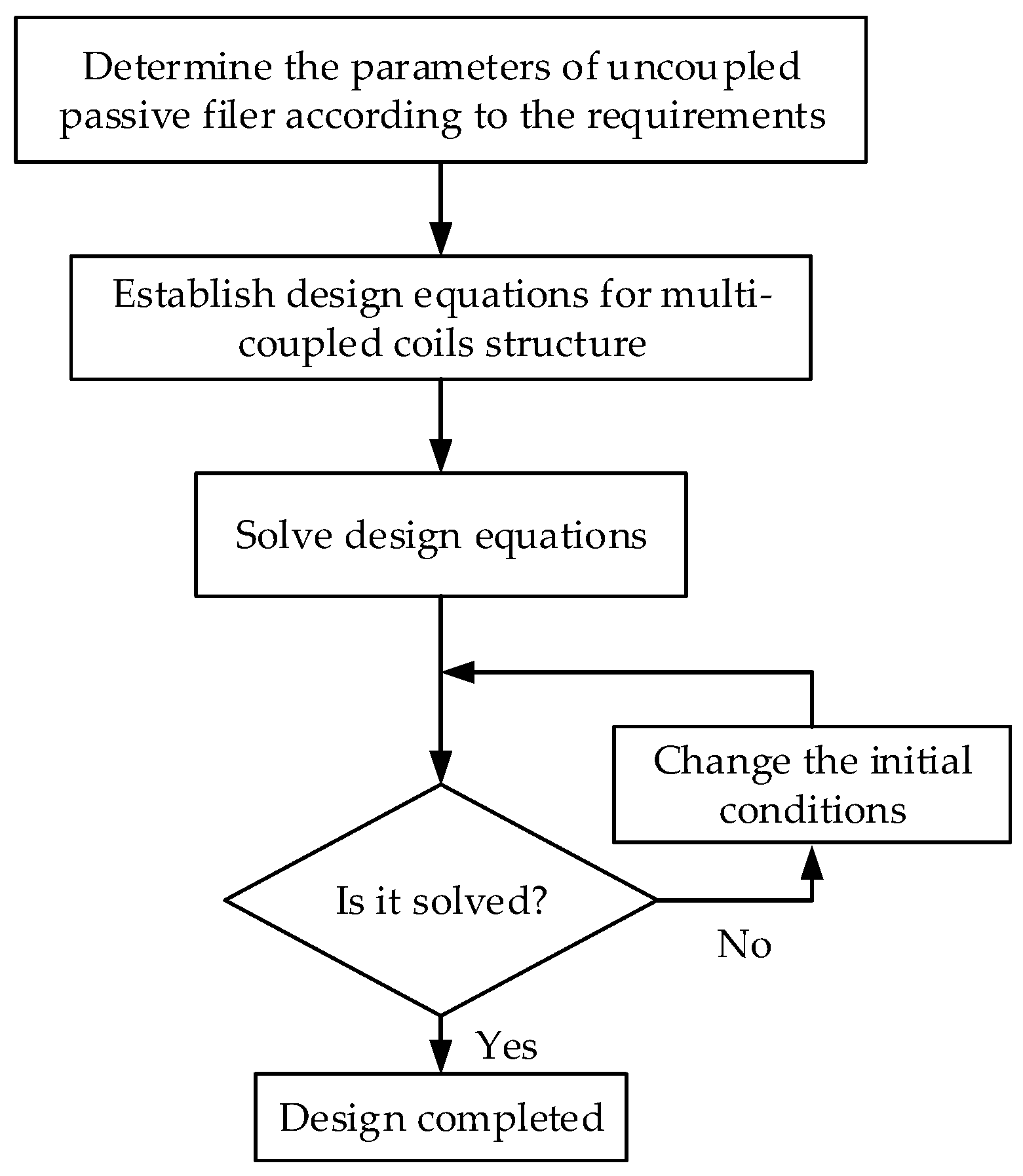
In the passive filter with multi-coupled coils, there are mutual inductances among the inductors. Therefore, in the design process, the self-inductances and mutual inductances need to be calculated and designed [5]. The basic design flow chart is shown in Figure 2.
According to Figure 2, the first step of the design process is to determine the parameters of the uncoupled passive filter considering the rated voltage, capacity. One type of uncoupled passive filter is shown in Figure 3a. In Figure 3a, the inductors La, Lb, Lc and the capacitors C3, C4, C5 are determined in this step.
The second step is to establish the design equations for the multi-coupled coils structure. Figure 3b shows the passive filter with multi-coupled coils. In Figure 3a,b, the values of capacitor C3, C4, C5 are the same. To make the network shown in Figure 3b equivalent to the network in Figure 3a, it is necessary to ensure that when the two networks have the same excitation, the voltages at point a, b, c, d and the current i1, i2, i3, i4, i5 in the two figures are the same. Moreover, according to this relationship, formulas are as follows:
in which, L1, L2, L3, L4, L5 are the self-inductances of the inductors in the passive filter with multi-coupled coils; Mij is the mutual inductance between Li and Lj (i, j = 1, 2, 3, 4, 5 and i ≠ j); La, Lb, Lc are the self-inductances of the inductors in the Cauer I form three-tuned filter.
L1 − 2M14 +L4 = La
−L4 + M12 − M13 +M14 − M24 + M34 = 0
M13 + M15 − M34 − M45 = 0
L2 + L3 + L4 + 2 M24 − 2 M34 − 2 M23 = Lb
−L3 + M23 + M25 + M34 − M35 + M45 = 0
L3 + L5 + 2 M35 = Lc
In (1)–(6), the self-inductances L1, L2, L3, L4, L5 and the mutual inductances M12, M13, M14, M15, M23, M24, M25, M34, M35, M45 are unknown quantities. Since the multi-coupled coils are designed as a layered structure of multiple coaxial round wire discs, the number of turns of each coil (N1, N2, N3, N4, N5) and the relative position between the coils (d1, d2, d3, d4, d5) determine the self-inductances and mutual inductances of the coils. Thus, (1)–(6) can be converted into equations about the number of coil turns (N1, N2, N3, N4, N5) and the relative positions of the coils (d1, d2, d3, d4, d5). There are 6 equations and 10 unknowns. Therefore, initial conditions are needed. We can set the position d1 of inductor L1, and set the coil turn N1 of L1 according to the value of La. Two mutual inductance relationships (such as: M12 = M13, M34 = M35) can be added. In this way, there are 8 equations and 8 unknowns, and the design equation set of the multi-coupled coils structure can be obtained.
The third step is to solve the nonlinear equations. The unknowns in the aforementioned equations can be worked out using the inductance calculation formula in [23,24]. If the nonlinear equations cannot be solved, the initial conditions shall be changed. In this way, the number of coil turns and the relative positions of the coils can be obtained. The passive filter with multi-coupled coils can be designed.
2.3. Structure of the HAPF with Multi-Coupled Coils
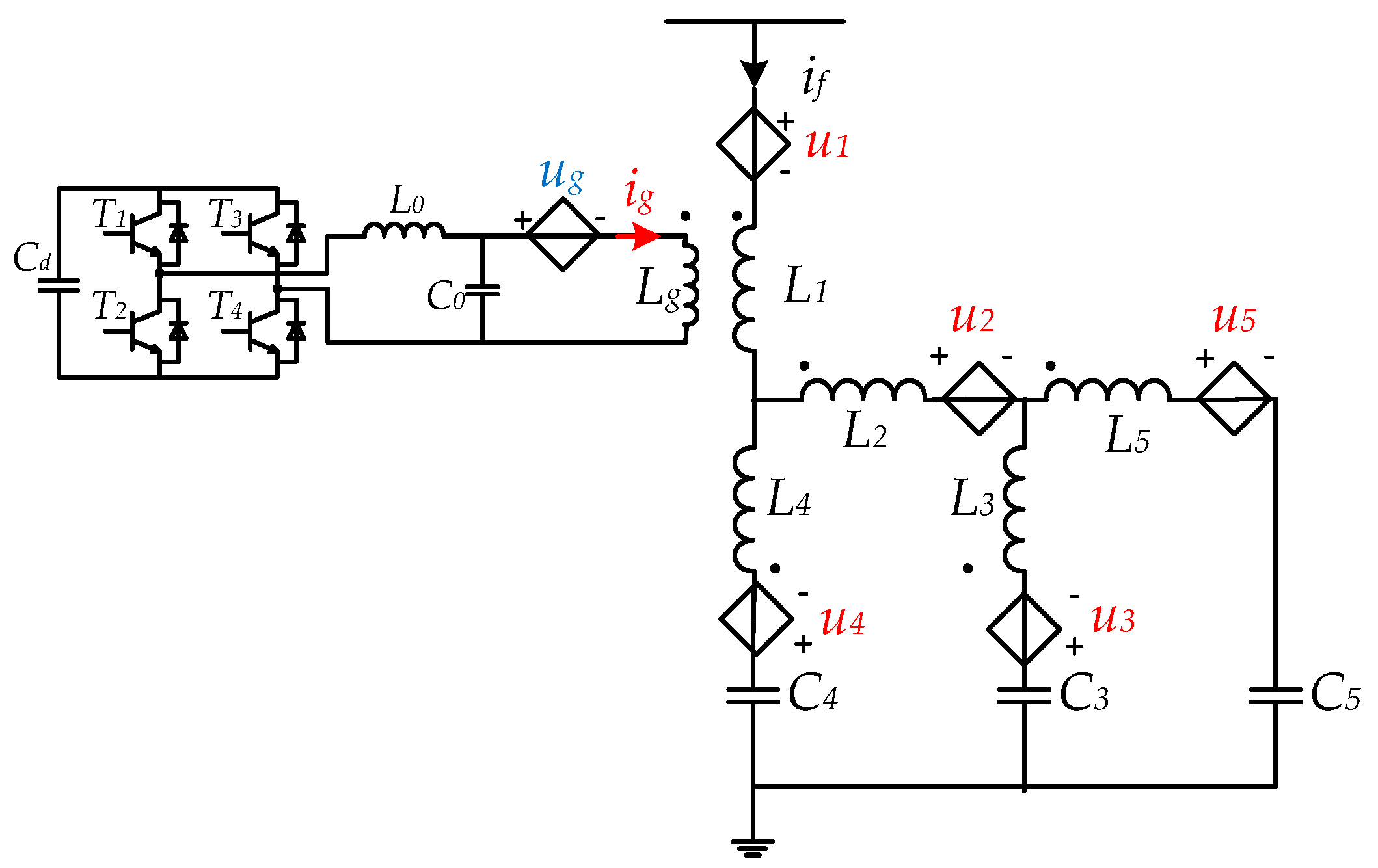
The topology of the HAPF with multi-coupled coils is shown in Figure 4, in which an active power filter is added to the passive filter. The active power filter consists of an H-bridge converter and a LCL filter. The inductor Lg of the LCL filter is the coupled inductor of the active power filter.
There are mutual inductances between the coupled inductor Lg and the inductors in the passive filter. The coupled inductor Lg is closest to inductor L1 and most closely coupled with L1. When the active power filter works, the converter generates a controllable AC current ig to the coupled inductor Lg. Since the spatial magnetic coupling exists among Lg and the inductors in the passive filter, a current can be injected into the passive filter branch, thereby changing the current of the passive filter branch if. Thus, the remaining characteristic harmonic currents after passive compensation can be eliminated.
Compared with the conventional shunt HAPF topology, the proposed HAPF has the similar current compensation principle. The passive filter of the proposed HAPF bears the fundamental voltage and eliminates most of the characteristic harmonic currents. The active power filter bears a very small fundamental voltage and eliminates the remaining harmonic currents.
In the proposed HAPF, the connection mode of the active power filter and the passive filter is different from the traditional HAPF. For the traditional HAPF topology in which the active power filter is in series with the passive filter through a transformer, the series connection of the transformer changes the filter loop of the passive filter. In Figure 4, the active power filter of the proposed HAPF connects with the passive filter through spatial magnetic coupling instead of a transformer. The coupled inductor Lg is designed as a round wire disc, which is placed very close to the multi-coupled coils in the passive filter. The coupled inductor Lg is not directly connected in series to the filter loop of the passive filter. So, the coupled inductor Lg does not change the filter loop of the passive filter. Compared to a transformer, the cost of the coupled inductor Lg in Figure 4 is relatively small in the entire HAPF. This connection mode ensures that whether the active converter is open-circuited or short-circuited, the filtering effect of the passive filter always exists and the safety of the power grid will not be at stake. Besides, the coaxial round wire discs inductor structure can enhance the coupling effect and increase the overall efficiency of the system.
3. Working Principle
The equivalent schematic of the hybrid compensation of the proposed HAPF is shown in Figure 5, where u1 to u5 are the induced voltages controlled by the output current ig of the converter through spatial magnetic coupling and ug is the voltage source controlled by all the currents of the passive filter.
Because the coupled inductor Lg is placed above the multi-coupled coils, it is closest to inductor L1, which is at the top of the multi-coupled coils. So, the mutual inductance Mg1 between Lg and L1 is relatively large, and the effect of the induced voltage source u1 is relatively large. For an inductor that is relatively far from Lg in space, the mutual inductance between it and Lg will be much smaller than Mg1.
The self-inductance and mutual inductance of each coil in Figure 1b were measured. The measurement results show that the mutual inductance Mg1 (between L1 and Lg) and Mg3 (between L3 and Lg) are much larger than Mg2 (between L2 and Lg), Mg4 (between L4 and Lg), and Mg5 (between L5 and Lg). Therefore, to simplify the theoretical analysis, the mutual inductance Mg2, Mg3, Mg4, Mg5 are combined to an equivalent inductance Mg’ in Figure 6, where u’ represents the equivalent induced voltage source generated in the filter branch by Mg’. For the characteristic harmonic, the impedance of the passive filter branch is very small. Lth and Rth represent the equivalent inductance and resistance of the passive filter branch at harmonic frequencies, respectively. Ls and Rs represent the supply-system inductance and resistance, respectively.
The current ifh represents the harmonic component of the filter branch current if. The current ifhw represents the passive current component of ifh, which is the harmonic component when only the passive filter works; the current ifhy represents the injected current component of ifh by the active power filter. iLh is the harmonic component of the load current iL. Figure 6 is only used to simplify the theoretical analysis.
According to Figure 6, the induced voltage u1 and u’ caused by ig can generate the injected current ifhy on the passive filter branch. In the harmonic current loop, Lth, Rth, Ls, and Rs will affect the value of ifhy.
At tuned frequencies, series resonance occurs in the passive filter branch and the values of Lth and Rth are very small. Therefore, at tuned frequencies, the current ig can produce a relatively large ifhy. By controlling the output current ig of the active power filter, the injected current component ifhy of ifh can be adjusted, then so can the harmonic ifh.
As long as the active power filter generates a current ig of a certain frequency, the injected current ifhy of corresponding frequency will be generated on the passive filter branch. Besides the tuned frequencies, the active power filter in the proposed HAPF can also filter harmonic currents at other frequencies. However, at these frequencies, the values of Lth and Rth are relatively large. Therefore, the current ifhy generated on the passive filter branch with the same magnitude of current ig will be relatively smaller than that generated at the tuned frequency.
When the amplitude of each characteristic harmonics of ifh and iLh are the same, and the phases are opposite, the harmonics in the supply current iS can be completely eliminated.
4. Control Strategy
When the active power filter of the proposed HAPF works, the accurate harmonic current tracking control is needed, as well as the capacitor voltage control on the DC side of the active converter. Therefore, the control block diagram of hybrid compensation is shown in Figure 7, which consists of three parts: DC voltage control module, current tracking control module, and current hysteresis control module.
The DC voltage control module is used to stabilize the DC capacitor voltage. The output of the DC voltage control module is idc,ref, which represents the reference value of the active current exchanged between the converter and the grid.
The current tracking control module is used to make the filter branch current accurately track the load harmonic current. The output of the current tracking control module is iL0h,ref.
The sum of idc,ref and iL0h,ref is iL0,ref, which is the input of the current hysteresis control module. The output of the current hysteresis control module is the PWM control signal of the active converter. The current hysteresis control can directly track the current at high speed, so the converter can be considered as a current source.
4.1. DC Capacitor Voltage Control
The stability of DC capacitor voltage is the prerequisite for the proposed HAPF to work stably. In order to maintain a stable DC capacitor voltage, it is necessary for the active converter to exchange active power with the induced voltage source ug.
Current idc is the active current, which is the active component of iL0. If the phase of idc is the same as the phase of ug, the converter absorbs active power from ug, to support the DC capacitor voltage. If the phase of idc is opposite to the phase of ug, the converter exports active power to ug. So, in Figure 8, it is critical to properly set the amplitude and phase of idc,ref, which is the reference value of idc.
To obtain the amplitude Idc,ref of current idc,ref, in Figure 8, the DC capacitor voltage udc is compared with the reference value udc,ref, and the comparison result is sent to the PI controller. The output of the PI controller is Idc,ref.
The induced voltage ug cannot be measured directly, and it is controlled by all the currents in the passive filter. Since the coupled inductor Lg is closest to inductor L1 and the most closely coupled with L1, only the filter branch current if (the current on inductor L1) is considered here. Then, ug can be expressed as:
where, Mg1 is the mutual inductance between the coupled inductor Lg and inductor L1.
So, according to (7), a unit signal idc0,ref, which has the same waveform with ug, can be obtained by current derivation, LPF, and waveform normalization in Figure 8. By multiplying idc0,ref to Idc,ref, the reference current idc,ref of the active current idc can be obtained.
Considering the 3rd, 5th, 7th, 11th harmonic components of idc, the active current idc can be expressed as:
where, an is the amplitude of each harmonic component of the unit signal idc0,ref.
When the phase of idc is the same with ug, ug can be expressed as:
The instantaneous power that ug exports is:
where, pac is the AC component, which represents the reactive power. Additionally, the DC component in (10) represents the active power, which is influenced by Idc,ref. Therefore, in DC capacitor voltage control, by controlling Idc,ref, the active power exchanged between the converter and ug can be adjusted to support the DC capacitor voltage. In addition, from (10), it can be seen that the active power is provided by the fundamental and harmonic components in ug together.
4.2. Harmonic Current Control
For harmonic current elimination, at the characteristic frequencies, the amplitude and phase of the output current ig are controlled to track the harmonic current.
Taking nth load harmonic as an example, current ifhn, ifhwn, ifhyn, iLhn, and ign are the nth component of current ifh, ifhw, ifhy, iLh, and ig, respectively. According to Figure 6, current ifhn, ifhwn, ifhyn can be expressed with phasor method as:
where, Ifhn, Ifhwn, Ifhyn, ILhn, Ign are the amplitude of ifhn, ifhwn, ifhyn, iLhn, and ign, respectively. θfhn, θfhwn, θfhyn, θLhn, θgn are the phase angles of ifhn, ifhwn, ifhyn, iLhn, and ign, respectively.
When the nth load harmonic current iLhn is completely eliminated, we have the following relationship:
Substituting (11)–(13) into (14) results in:
where, , , .
In (15), the amplitude Ign and phase angle θgn of current ign are adjustable. When the nth load harmonic current iLhn is definite, there is a unique Ign and a unique θgn that suit Equation (15).
From (15), Ign and θgn should be:
According to (16) and (17), Ign and θgn are only related to nth load harmonic current iLhn. Therefore, in theory, the nth harmonic current iLhn can be completely eliminated by controlling the amplitude and phase angle of the output current ign of the active power filter.
Consequently, the active power filter is controlled as an adjustable current source. Each characteristic harmonic ign of output current ig is controlled individually. Through joint control of the amplitude and phase of ign, each characteristic harmonic ifhn of the filter branch current if can be adjusted, thereby eliminating the load harmonic current iLh.
As shown in Figure 9, the amplitude and phase of each characteristic harmonic component of the load current iL and filter branch current if can be obtained by FFT. The amplitudes and phases obtained from iL are reference values. The amplitudes and phases obtained from if are feedback signals.
These reference values and feedback signals are sent to their respective PI controllers, and then synthesized to obtain the reference signal for hysteresis control. Finally, the PWM control signal of the active converter is obtained. The hysteresis control can track the current iL0 well and the active power filter can generate the desired current ig. In this paper, the width of the hysteresis band is 0.2 A.
In order to improve response speed, the phase feedforward control is adopted, which is shown in Figure 9. In the phase feedforward control, pdif3 is the phase response with the 3rd harmonic of iL0 as the excitation and the 3rd harmonic of current if as the output. k is the coefficient of the phase feedforward control, whose value is slightly less than 1. The phase response can be obtained through simulation, and its value does not need to be precise.
5. Simulation Results
In order to verify the effectiveness of the proposed scheme, simulations of a single-phase 10 kV hybrid active power filter with multi-coupled coils, which is shown in Figure 4, are carried out in MATLAB/Simulink. The load harmonic source includes 5th, 7th, and 11th harmonic current. The inductance parameters and capacitance parameters of the multi-coupled coils are calculated according to the method in [5]. The main simulation parameters except for the inductance parameters of the multi-coupled coils are shown in Table 1.
The inductance matrix of the multi-coupled coils is shown in Table 2.
According to the inductance and capacitance parameters in Table 1 and Table 2, the impedance–frequency characteristic of the passive filter is simulated as shown in Figure 10.
Figure 10 shows the tuned frequencies of the passive filter deviate from 250 Hz, 350 Hz, and 550 Hz (line frequency is 50 Hz in China). So, the passive filter is unable to completely eliminate the 5th, 7th, and 11th characteristic harmonics.
To improve the filtering effect of the passive filter, the active power filter generates current ig to compensate the remaining harmonic currents. In the hybrid compensation simulations, the control strategy shown in Figure 7, Figure 8 and Figure 9 is used.
5.1. Current Compensation Effect
Figure 11 shows the waveforms of supply current iS under different compensation strategies. The waveform of iS without any compensation is shown in Figure 11a. The waveform of iS with passive compensation is shown in Figure 11b. The waveform of iS with hybrid compensation is shown in Figure 11c.
From Figure 11a, it can be seen that without any compensation, the total harmonic distortion (THD) of iS is 26.33%. Further, the distortion of 5th, 7th, and 11th harmonics of iS are 19.57%, 14.66%, and 9.74%, respectively. From Figure 11b, it can be seen that with passive compensation, the THD of iS is reduced to 5.79%. Further, the distortion of 5th, 7th, and 11th harmonics are 4.55%, 3.36%, and 1.22%, respectively. From Figure 11c, it can be seen that the THD of iS is reduced to 0.38%. The distortion of 5th, 7th, and 11th harmonics are 0.27%, 0.26%, and 0.09%, respectively.
In addition, it can be seen that in Figure 11a, the amplitude of the fundamental component of iS is 204.1 A. While in Figure 11b,c, the amplitude of the fundamental component of iS is 340 A, which is larger. The reason is that after the passive filter works, the capacitive fundamental current increases, which can compensate the inductive current in the grid.
5.2. Compensation Characteristic Simulation
In hybrid compensation, the stability of DC capacitor voltage is the prerequisite. The output current ig will directly change the filter branch current if and affect the filtering effect.
In order to study the compensation characteristic, Figure 12a–c shows the waveform of the output current ig of the active power filter, the waveform of the filter branch current if, and the waveform of the DC capacitor voltage udc in hybrid compensation, respectively.
In Figure 12a, the amplitude of the 5th, 7th, and 11th harmonics of ig are 27.51 A, 51.34 A, and 4.90 A, respectively. These harmonic currents are injected into the filter branch through spatial magnetic coupling, to change the filter branch current if.
In Figure 12b, the amplitude of the 5th, 7th, and 11th harmonics of if are 39.92 A, 29.54 A, and 19.98 A, respectively. The harmonic components ifh of if in hybrid compensation includes the passive current component ifhw (the harmonic component when only the passive filter works) and the injected current component ifhy (injected by the active power filter).
From Figure 12c, it can be seen that in hybrid compensation, the DC capacitor voltage udc can be stabilized at 800 V with only small voltage fluctuations. The cause of the fluctuation is the active power exchange between the converter and the induced voltage ug.
The apparent power of the active power filter can be calculated using the following equation:
in which, SAPF represents the apparent power of the active power filter; Vd represents the DC voltage of the active power filter; Igrms represents the RMS value of the output current ig.
In simulation, Vd is 800 V. Igrms is 41.33 A. So, the apparent power SAPF = 23.38 kVA, according to (18).
The apparent power of the proposed HAPF can be calculated using the following equation:
in which, SHAPF represents the apparent power of the proposed HAPF; UFrms represents the RMS value of the voltage of the proposed HAPF; Ifrms represents the RMS value of the current if.
In simulation, Ifrms is 194.35 A, and UFrms is 5845 V. So, the apparent power SHAPF = 1135.975 kVA, according to (19).
SPF represents the apparent power of the passive filter. The ratio between SAPF and SPF is:
It can be found that the capacity ratio of the active power filter to the passive filter in the proposed HAPF is very small.
5.3. Fault Simulation of the Active Power Filter
The open-circuit and short-circuit fault diagram of the active power filter is shown in Figure 13. As is introduced before, the proposed HAPF has no additional coils in series connected to the passive filter branch, and the filtering effect of the passive filter will be guaranteed whether the active power filter is open or short-circuited. To verify this, simulations in two cases (open-circuit and short-circuit) are conducted.
According to Figure 13, under normal working condition, point a and point b are connected to each other, while point b and point c are not connected. When the connection between point a and point b is broken, the active power filter is open-circuited. At this time, the current ig is zero and the influence of the active power filter on the passive filter no longer exists. The open-circuit fault simulation result is shown in Figure 14a. Compared with the waveform of iS when only the passive filter works in Figure 11b, the waveform of iS in Figure 14a is almost the same.
When point b and point c are connected, the active power filter is short-circuited. In this case, current ig is completely generated by the induced voltage ug. At this time, the influence of the current ig on the passive filter is small. The short-circuit fault simulation result is shown in Figure 14b. Compared with the waveform in Figure 11b, the waveform of iS in Figure 14b is very similar.
In summary, whether the active power filter is open-circuited or short-circuited, the filtering effect of the passive filter can be guaranteed.
5.4. Simulation of Three-Phase Hybrid Active Power Filter
To prove that the proposed HAPF topology is available for the three-phase system, a three-phase 10 kV hybrid active power filter simulation was carried out. In the three-phase system, three single-phase hybrid active power filters are used. Each single-phase hybrid active power filter has the same topology and the same control strategy as described above. The parameters are the same as the parameters in Table 1 and Table 2.
Figure 15 shows the waveforms of the supply current iS under different compensation strategies in the three-phase simulation. The waveform of iS without any compensation is shown in Figure 15a. The waveform of iS with passive compensation is shown in Figure 15b. The waveform of iS with hybrid compensation is shown in Figure 15c.
In Figure 15a, taking phase A as an example, without any compensation, the THD of the supply current iSa is 26.29%. The distortion of 5th, 7th, and 11th harmonics of iSa is 19.56%, 14.64%, and 9.71%, respectively. In Figure 15b, with passive compensation, the THD of iSa is reduced to 5.81%. Further, the distortion of 5th, 7th, and 11th harmonics are 4.55%, 3.37%, and 1.29%, respectively. In Figure 15c, with hybrid compensation, the THD of iSa is reduced to 0.29%.
6. Experiments
In order to verify the feasibility of the proposed HAPF, a small prototype of multi-coupled coils is designed and manufactured as shown in Figure 1b. Then, an experimental platform of the hybrid active power filter with multi-coupled coils is built according to the topology in Figure 4.
The structure schematic diagram of the HAPF experimental platform is shown in Figure 16. The platform is composed of the system power supply, harmonic source, and the proposed HAPF. The RMS value of the system voltage is transformed from 220 V to 36 V through a step-down transformer. The harmonic source is an adjustable harmonic current source. The HAPF with multi-coupled coils is composed of an active power filter and passive filter. The active power filter consists of the main circuit, detection circuit, and control circuit.
The experimental platform of HAPF with multi-coupled coils is shown in Figure 17. The main experimental parameters other than the inductance parameters of the multi-coupled coils are shown in Table 3.
The inductance parameters of the multi-coupled coils in the platform are shown in Table 4.
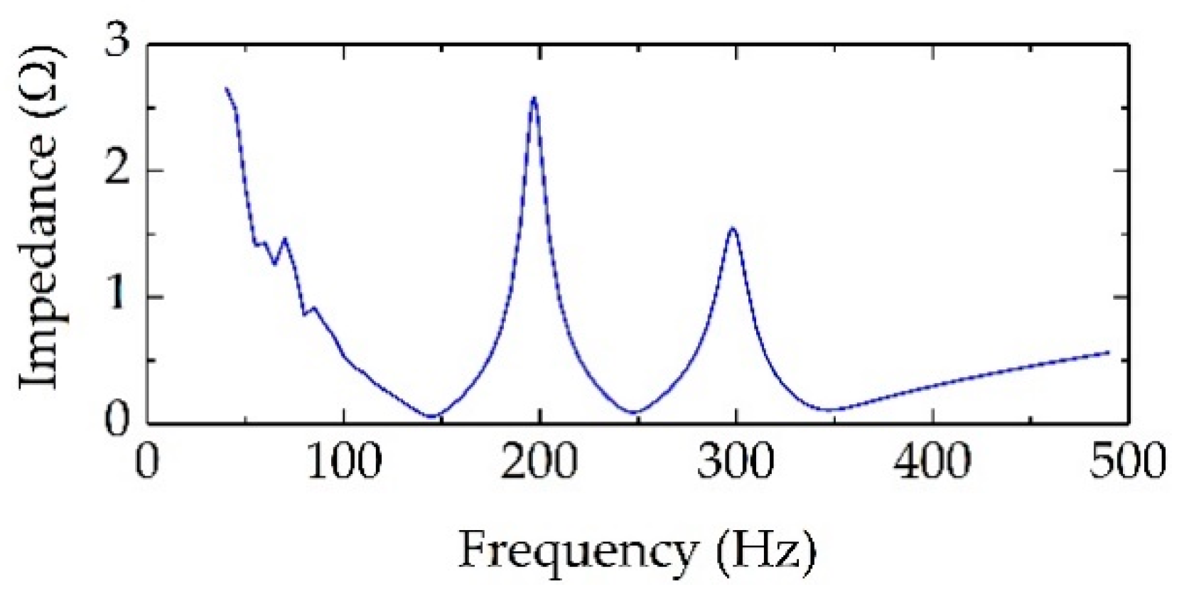
The impedance–frequency characteristic of the passive filter in the experiment is measured by voltammetry as shown in Figure 18. From Figure 18, it can be seen that the measured tuned frequencies of the passive filter are 145 Hz, 247 Hz, and 347 Hz, which slightly deviate from the frequencies of the 3rd, 5th, and 7th harmonics.
In the experiment, the load harmonic current source injects the 3rd harmonic current into the power grid, whose amplitude is 14.1 A.
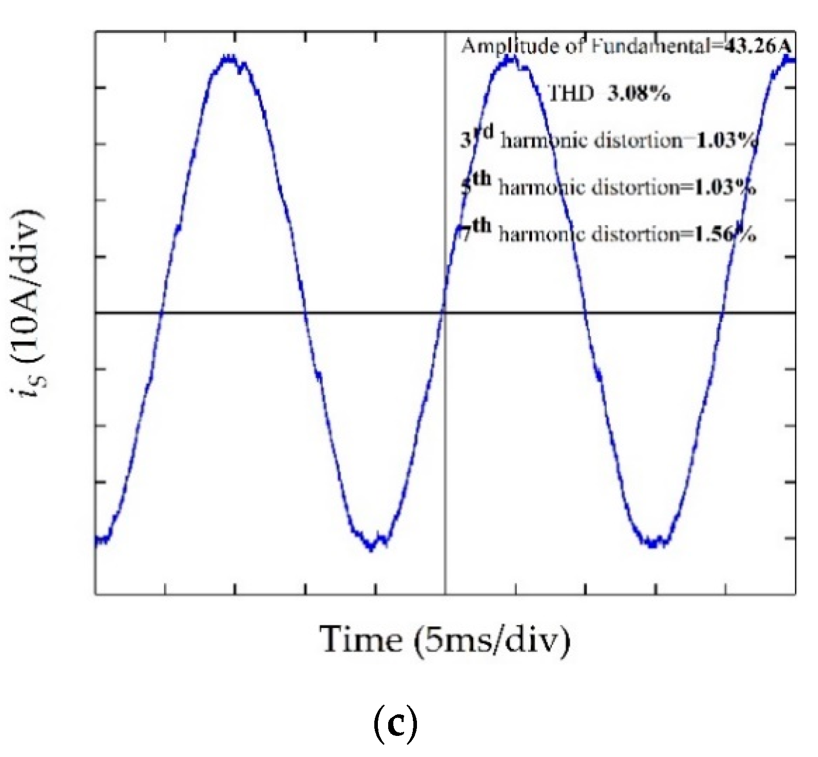
Figure 19 shows the experimental waveform of the supply current iS under different compensation strategies. The experimental waveform of iS without compensation is shown in Figure 19a. The experimental waveform of iS with passive compensation is shown in Figure 19b. The experimental waveform of iS with hybrid compensation is shown in Figure 19c.
From Figure 19a, it can be seen that iS contains the obvious 3rd harmonic. The amplitude of the fundamental component of the supply current iS is 23.65 A and the THD is 60.95%. The distortion of the 3rd harmonic of supply current iS is 60.68%.
From Figure 19b, it can be seen that amplitude of the fundamental component of iS is 43.9 A, which is larger than that before compensation because of the increase of capacitive fundamental current. The THD of iS is reduced to 15.93%. The distortion of the 3rd harmonic is reduced to 13.22%. At the same time, the distortion of the 5th harmonic is 5.92%, and the distortion of the 7th harmonic is 6.16%.
In passive compensation, the 5th and 7th harmonic currents appear in the supply current iS, which is caused by the very small impedance of the system transformer in the experiment. For the 5th and 7th harmonics, the impedance of the passive filter branch is very small, so the 5th and 7th harmonics are introduced from the power grid.
From Figure 19c, it can be seen that the amplitude of the fundamental component of the supply current iS is 43.26 A and the THD is reduced to 3.08%. The 3rd, 5th, 7th harmonics of iS are greatly eliminated. Thus, it is reasonable to conclude that the proposed hybrid compensation method is feasible.
7. Conclusions
This paper proposes a novel hybrid active power filter with multi-coupled coils. The passive filter of the proposed HAPF adopts the structure of multi-coupled coils, which can reduce the required space of the inductors. The active power filter of the proposed HAPF adopts a coupled inductor instead of a transformer to connect with the passive filter. The active power filter can inject the compensation current into the passive filter branch through spatial magnetic coupling. At the same time, through spatial magnetic coupling, the active power filter can absorb active power from the passive filter branch to maintain the capacitor voltage.
To verify the effectiveness of the proposed scheme, a simulation model of a 10 kV hybrid active power filter with multi-coupled coils is built in MATLAB/Simulink. Furthermore, an experimental platform of hybrid active power filter with multi-coupled coils is built. Simulations and experiments in this paper verify the feasibility of the proposed HAPF.
- (1)
- The passive filter with multi-coupled coils can save the required space of the inductors on the premise of eliminating characteristic harmonics.
- (2)
- The active power filter of the proposed HAPF can improve the filtering effect of the passive filter. The current injection through spatial magnetic coupling is effective and feasible.
- (3)
- Since the connection method of spatial magnetic coupling, whether the active power filter is open-circuited or short-circuited, the filtering effect of the passive filter can still be guaranteed, which enhances the reliability of the filter.
In the simulation and experiment, it can be found that the inductance matrix of the multi-coupled coils directly affects the performance of the filter. Therefore, the parameter optimization of the multi-coupled coils is worthy of further research.
Author Contributions
Conceptualization, B.C., C.T. and Y.L.; methodology, Y.C., G.X. and J.Y.; software, G.X., Y.C.; validation, G.X., Y.Z. and G.C.; writing—original draft preparation, G.X.; writing—review and editing, G.X.; supervision, B.C. All authors have read and agreed to the published version of the manuscript.
Funding
This research received no external funding.
Data Availability Statement
The data presented in this study are available on request from the corresponding author.
Conflicts of Interest
The authors declare no conflict of interest.
References
- Bhattacharya, A.; Chakraborty, C.; Bhattacharya, S. Shunt compensation. IEEE Ind. Electron. Mag. 2009, 3, 38–49. [Google Scholar] [CrossRef]
- Kanjiya, P.; Khadkikar, V.; Zeineldin, H.H. Optimal Control of Shunt Active Power Filter to Meet IEEE Std. 519 Current Harmonic Constraints under Nonideal Supply Condition. IEEE Trans. Ind. Electron. 2015, 62, 724–734. [Google Scholar] [CrossRef]
- Badrzadeh, B.; Smith, K.S.; Wilson, R.C. Designing Passive Harmonic Filters for an Aluminum Smelting Plant. IEEE Trans. Ind. Appl. 2011, 47, 973–983. [Google Scholar] [CrossRef]
- Li, X.; Xu, W.; Ding, T. Damped High Passive Filter—A New Filtering Scheme for Multipulse Rectifier Systems. IEEE Trans. Power Deliv. 2017, 32, 117–124. [Google Scholar] [CrossRef]
- Chen, B.; Zhou, X.; Luo, Y.; Zhu, Y. Design of compact multi-tuned filter with coupled inductors. Electr. Mach. Control 2019, 23, 60–68. (In Chinese) [Google Scholar]
- Sun, X.; Han, R.; Shen, H.; Wang, B.; Lu, Z.; Chen, Z. A Double-Resistive Active Power Filter System to Attenuate Harmonic Voltages of a Radial Power Distribution Feeder. IEEE Trans. Power Electron. 2016, 31, 6203–6216. [Google Scholar] [CrossRef]
- Carpinelli, G.; Proto, D.; Russo, A. Optimal Planning of Active Power Filters in a Distribution System Using Trade-off/Risk Method. IEEE Trans. Power Deliv. 2017, 32, 841–851. [Google Scholar] [CrossRef]
- Bosch, S.; Staiger, J.; Steinhart, H. Predictive Current Control for an Active Power Filter with LCL-Filter. IEEE Trans. Ind. Electron. 2018, 65, 4943–4952. [Google Scholar] [CrossRef]
- Salmerón, P.; Litrán, S.P. A Control Strategy for Hybrid Power Filter to Compensate Four-Wires Three-Phase Systems. IEEE Trans. Power Electron. 2010, 25, 1923–1931. [Google Scholar] [CrossRef]
- Corasaniti, V.F.; Barbieri, M.B.; Arnera, P.L.; Valla, M.I. Hybrid Active Filter for Reactive and Harmonics Compensation in a Distribution Network. IEEE Trans. Ind. Electron. 2009, 56, 670–677. [Google Scholar] [CrossRef] [Green Version]
- Dey, P.; Mekhilef, S. Current harmonics compensation with three-phase four-wire shunt hybrid active power filter based on modified D–Q theory. IET Power Electron. 2015, 8, 2265–2280. [Google Scholar] [CrossRef] [Green Version]
- Rahmani, S.; Hamadi, A.; Mendalek, N.; Al-Haddad, K. A New Control Technique for Three-Phase Shunt Hybrid Power Filter. IEEE Trans. Ind. Electron. 2009, 56, 2904–2915. [Google Scholar] [CrossRef]
- Rahmani, S.; Hamadi, A.; Al-Haddad, K.; Dessaint, L.A. A Combination of Shunt Hybrid Power Filter and Thyristor-Controlled Reactor for Power Quality. IEEE Trans. Ind. Electron. 2014, 61, 2152–2164. [Google Scholar] [CrossRef]
- Wang, L.; Lam, C.; Wong, M.; Dai, N.; Lao, K.; Wong, C. Non-linear adaptive hysteresis band pulse-width modulation control for hybrid active power filters to reduce switching loss. IET Power Electron. 2015, 8, 2156–2167. [Google Scholar] [CrossRef] [Green Version]
- Wang, L.; Lam, C.; Wong, M. Unbalanced Control Strategy for A Thyristor-Controlled LC-Coupling Hybrid Active Power Filter in Three-Phase Three-Wire Systems. IEEE Trans. Power Electron. 2017, 32, 1056–1069. [Google Scholar] [CrossRef]
- Wang, L.; Lam, C.; Wong, M. Selective Compensation of Distortion, Unbalanced and Reactive Power of a Thyristor-Controlled LC-Coupling Hybrid Active Power Filter (TCLC-HAPF). IEEE Trans. Power Electron. 2017, 32, 9065–9077. [Google Scholar] [CrossRef]
- Tareen, W.U.K.; Mekhielf, S. Three-Phase Transformerless Shunt Active Power Filter with Reduced Switch Count for Harmonic Compensation in Grid-Connected Applications. IEEE Trans. Power Electron. 2018, 33, 4868–4881. [Google Scholar] [CrossRef]
- Balasubramanian, R.; Parkavikathirvelu, K.; Sankaran, R.; Amirtharajan, R. Design, Simulation and Hardware Implementation of Shunt Hybrid Compensator Using Synchronous Rotating Reference Frame (SRRF)-Based Control Technique. Electronics 2019, 8, 42. [Google Scholar] [CrossRef] [Green Version]
- Shuai, Z.; Luo, A.; Zhu, W.; Fan, R.; Zhou, K. Study on a Novel Hybrid Active Power Filter Applied to a High-Voltage Grid. IEEE Trans. Power Deliv. 2009, 24, 2344–2352. [Google Scholar] [CrossRef]
- Luo, A.; Shuai, Z.; Zhu, W.; Fan, R.; Tu, C. Development of Hybrid Active Power Filter Based on the Adaptive Fuzzy Dividing Frequency-Control Method. IEEE Trans. Power Deliv. 2009, 24, 424–432. [Google Scholar] [CrossRef]
- Shuai, Z.; Luo, A.; Shen, J.; Wang, X. Double Closed-Loop Control Method for Injection-Type Hybrid Active Power Filter. IEEE Trans. Power Electron. 2011, 26, 2393–2403. [Google Scholar] [CrossRef]
- Nguyen, T.N.; Luo, A.; Shuai, Z.; Chau, M.T.; Li, M.; Zhou, L. Generalised design method for improving control quality of hybrid active power filter with injection circuit. IET Power Electron. 2014, 7, 1204–1215. [Google Scholar] [CrossRef]
- Zhou, X.; Chen, B.; Luo, Y.; Zhu, R. Analytical Calculation of Mutual Inductance of Finite-Length Coaxial Helical Filaments and Tape Coils. Energies 2019, 12, 566. [Google Scholar] [CrossRef] [Green Version]
- Luo, Y.; Wang, X.; Zhou, X. Inductance Calculations for Circular Coils with Rectangular Cross Section and Parallel Axes Using Inverse Mellin Transform and Generalized Hypergeometric Functions. IEEE Trans. Power Electron. 2017, 32, 1367–1374. [Google Scholar] [CrossRef]
- IEEE Guide for the Application and Specification of Harmonic Filters. In IEEE 1531, 2020 ed.; Institute of Electrical and Electronics Engineers (IEEE): New York, NY, USA, 2021; pp. 1–71. [CrossRef]
Figure 1.
Passive filter of HAPF with multi-coupled coils. (a) Schematic diagram of the passive filter. (b) Prototype of multi-coupled coils.
Figure 1.
Passive filter of HAPF with multi-coupled coils. (a) Schematic diagram of the passive filter. (b) Prototype of multi-coupled coils.

Figure 2.
Basic design flow chart of the passive filer with multi-coupled coils structure.

Figure 3.
Passive filter. (a) Cauer I form three-tuned filter circuit. (b) Passive filter with multi-coupled coils.
Figure 3.
Passive filter. (a) Cauer I form three-tuned filter circuit. (b) Passive filter with multi-coupled coils.

Figure 4.
Topology of novel HAPF with multi-coupled coils.

Figure 5.
Equivalent schematic of the hybrid compensation.

Figure 6.
Simplified schematic of hybrid compensation.

Figure 7.
The control block diagram of hybrid compensation.

Figure 8.
DC capacitor voltage control block diagram.

Figure 9.
Block diagram of harmonic current control strategy.

Figure 10.
Impedance–frequency characteristic of the passive filter.

Figure 11.
Supply current iS. (a) Supply current iS without any compensation. (b) Supply current iS when only the passive filter works. (c) Supply current iS with hybrid compensation.
Figure 11.
Supply current iS. (a) Supply current iS without any compensation. (b) Supply current iS when only the passive filter works. (c) Supply current iS with hybrid compensation.

Figure 12.
Compensation characteristic waveform. (a) Output current ig of the active power filter in hybrid compensation. (b) Filter branch current if in hybrid compensation. (c) DC capacitor voltage udc in hybrid compensation.
Figure 12.
Compensation characteristic waveform. (a) Output current ig of the active power filter in hybrid compensation. (b) Filter branch current if in hybrid compensation. (c) DC capacitor voltage udc in hybrid compensation.

Figure 13.
Open-circuit and short-circuit fault diagram of the active power filter.

Figure 14.
Supply current iS when the active power filter fails. (a) Supply current iS when the active power filter is open-circuited. (b) Supply current iS when the active power filter is short-circuited.
Figure 14.
Supply current iS when the active power filter fails. (a) Supply current iS when the active power filter is open-circuited. (b) Supply current iS when the active power filter is short-circuited.

Figure 15.
Supply current iS in three-phase system. (a) Supply current iS without any compensation. (b) Supply current iS when only the passive filter works. (c) Supply current iS with hybrid compensation.
Figure 15.
Supply current iS in three-phase system. (a) Supply current iS without any compensation. (b) Supply current iS when only the passive filter works. (c) Supply current iS with hybrid compensation.

Figure 16.
Structure schematic diagram of the HAPF experimental platform.

Figure 17.
Experimental platform of HAPF with multi-coupled coils.

Figure 18.
Measured impedance–frequency characteristic of the passive filter.

Figure 19.
Supply current iS in the experiment. (a) Supply current iS without compensation. (b) Supply current iS with passive compensation. (c) Supply current iS with hybrid compensation.
Figure 19.
Supply current iS in the experiment. (a) Supply current iS without compensation. (b) Supply current iS with passive compensation. (c) Supply current iS with hybrid compensation.


Table 1.
Main simulation parameters.
| Categories | Variables | Value |
|---|---|---|
| Supply-system parameters | voltage | 10 kV |
| frequency | 50 Hz | |
| LS | 1.2 mH | |
| Load harmonic parameters | amplitude of 5th harmonic | 40 A |
| amplitude of 7th harmonic | 30 A | |
| amplitude of 11th harmonic | 20 A | |
| Converter parameters | L0 | 0.8 mH |
| C0 | 6 μF | |
| Cdc | 4700 μF | |
| udc | 800 V | |
| Passive filter parameters | C3 | 25 μF |
| C4 | 55 μF | |
| C5 | 21 μF |
Table 2.
Inductance matrix of 10 kV HAPF with multi-coupled coils.
| Inductance/μH | Lg | L1 | L2 | L3 | L4 | L5 |
|---|---|---|---|---|---|---|
| Lg | 4088 | 1061 | 103 | 1578 | 116 | 109 |
| L1 | 1061 | 813 | 61 | 1047 | 60 | 62 |
| L2 | 103 | 61 | 800 | 721 | 330 | 662 |
| L3 | 1578 | 1047 | 721 | 10793 | 557 | 695 |
| L4 | 116 | 60 | 330 | 557 | 7364 | 547 |
| L5 | 109 | 62 | 662 | 695 | 547 | 1168 |
Table 3.
Main experimental parameters.
| Categories | Variables | Value |
|---|---|---|
| Supply-system parameters | voltage | 36 V |
| frequency | 50 Hz | |
| LS | 0.12 mH | |
| Load harmonic parameters | amplitude of 3rd harmonic | 14.1 A |
| Passive filter parameters | C3 | 352.9 μF |
| C4 | 1269.7 μF | |
| C5 | 399.1 μF |
Table 4.
Inductance matrix of multi-coupled coils in experimental platform.
| Inductance/μH | Lg | L1 | L2 | L3 | L4 | L5 |
|---|---|---|---|---|---|---|
| Lg | 980.0 | 155.0 | 37.1 | 258.8 | 13.2 | 45.9 |
| L1 | 155.0 | 80.1 | 10.8 | 86.4 | 3.4 | 11.4 |
| L2 | 37.1 | 10.8 | 106.8 | 90.2 | 9.0 | 57.5 |
| L3 | 258.8 | 86.4 | 90.2 | 746.7 | 17.5 | 79.6 |
| L4 | 13.2 | 3.4 | 9.0 | 17.5 | 872.8 | 62.7 |
| L5 | 45.9 | 11.4 | 57.5 | 79.6 | 62.7 | 687.7 |
Publisher’s Note: MDPI stays neutral with regard to jurisdictional claims in published maps and institutional affiliations. |
© 2021 by the authors. Licensee MDPI, Basel, Switzerland. This article is an open access article distributed under the terms and conditions of the Creative Commons Attribution (CC BY) license (https://creativecommons.org/licenses/by/4.0/).
Share and Cite
MDPI and ACS Style
Xue, G.; Chen, B.; Tian, C.; Yuan, J.; Zhou, Y.; Chen, G.; Luo, Y.; Chen, Y. A Novel Hybrid Active Power Filter with Multi-Coupled Coils. Electronics 2021, 10, 998. https://0-doi-org.brum.beds.ac.uk/10.3390/electronics10090998
AMA Style
Xue G, Chen B, Tian C, Yuan J, Zhou Y, Chen G, Luo Y, Chen Y. A Novel Hybrid Active Power Filter with Multi-Coupled Coils. Electronics. 2021; 10(9):998. https://0-doi-org.brum.beds.ac.uk/10.3390/electronics10090998
Chicago/Turabian StyleXue, Gang, Baichao Chen, Cuihua Tian, Jiaxin Yuan, Yuxiong Zhou, Guanru Chen, Yao Luo, and Yaojun Chen. 2021. "A Novel Hybrid Active Power Filter with Multi-Coupled Coils" Electronics 10, no. 9: 998. https://0-doi-org.brum.beds.ac.uk/10.3390/electronics10090998
Note that from the first issue of 2016, this journal uses article numbers instead of page numbers. See further details here.