Article

Design and Analysis of an Eight-Port Dual-Polarized High-Efficiency Shared-Radiator MIMO Antenna for 5G Mobile Devices

College of Electronic and Information Engineering, Inner Mongolia University, Hohhot 010021, China
*
Authors to whom correspondence should be addressed.
These authors contributed equally to this work.
Submission received: 22 April 2022 / Revised: 17 May 2022 / Accepted: 18 May 2022 / Published: 20 May 2022
(This article belongs to the Special Issue Recent Advances in MIMO and Array Antennas)

Abstract

:
Nowadays, the MIMO can achieve fifth generation (5G) ultra-high capacity, but it is a great challenge for the smartphone antenna to achieve good isolation, high efficiency, and other performance in limited space. The paper designed and completed an eight-port dual-polarized high-efficiency shared-radiator antenna working in 3.5 GHz (3.4–3.6 GHz) for 5G mobile devices. The two antenna elements are regarded as one building block and share one radiator, and the size of one radiator is 17.1 × 17.1 mm 2 (0.02 λ × 0.02 λ , where λ presents the free-space wavelength at 3.5 GHz). The MIMO system consists of four radiators, and the edge-to-edge distance between the radiators on the short side is 31.9 mm (0.038 λ ), and the total size of the MIMO antenna system is 150 × 80 × 1.6 mm 3 (0.176 λ × 0.094 λ × 0.0019 λ ). The antenna uses an orthogonal placement of feed lines to produce dual polarization in the MIMO system, resulting in high isolation without introducing other decoupling structures. In addition, the reason for the high efficiency of the antenna is explained by the common mode (CM) and differential model (DM). Finally, the simulated results are as follows: the isolation is 14 dB; the total efficiency (TE) is 75–85%; the envelope correlation coefficient (ECC) is lower than 0.065; and the gain is 6.5 dB. The prototype is fabricated and tested: the isolation is better than 17 dB, the range of the measured TE is 60–75%, and the ECC is lower than 0.045. In addition, the influence of the human body model on the antenna are also discussed. Overall, the proposed MIMO antenna has a shared radiator with high isolation and high TE, and is more suitable for the current stage of 5G MIMO antenna technology. More importantly, the planar structure block is very simple to build and easy to fabricate on the substrate.

1. Introduction

With the human society progressing and developing, the disruptive growth in performance requirements of wireless communication systems, such as data throughput, energy efficiency, latency and security, is stimulating research and the development of new solutions to serve the largest possible number of users [1]. However, the current 4G (fourth generation) mobile cellular systems and the antenna equipment associated with them are no longer able to meet the growing volume of services. Compared to 4G systems, the 5G wireless communication system technology is mainly composed of MIMO technology to improve spectral efficiency [2,3,4], making the 5G ultra-fast with ultra-low latency and extremely high reliability. In addition, with the global commercialization of 5G, many countries, including China, the US, European countries, Japan, and South Korea, have started to explore the 6G (sixth generation) mobile communications on top of 5G to better meet people’s needs [5].Therefore, it has become imperative to significantly increase the channel capacity of antennas applied to 5G mobile terminal equipment [6]. MIMO is one of the technologies that can achieve ultra-high capacity in 5G [6]. The frequency band of 3.4–3.6 GHz was allocated for future global mobile broadband services and the 5G mobile communications at the 2015 World Radiocommunication Conference. Since then, the related sub-6 GHz MIMO antenna design has received a lot of attention from researchers [7,8]. Currently, six, eight, or even more antenna elements are integrated into mobile terminal devices to increase the channel capacity of the devices [9,10,11]. However, with so many antennas integrated in the limited space of a mobile phone, the mutual coupling between antenna elements can affect the orthogonality between different data streams, thus deteriorating the channel capacity of the MIMO system [12], so it is important to require good isolation between the antennas.
Researchers have proposed many methods to increase the isolation for the MIMO antenna. For example, additional decoupling structures are utilized to reduce the current of coupled antenna from the excited antenna. The ways to reduce the coupling current include parasitic element decoupling [13,14], neutralization line (NL) decoupling [15,16,17], defective ground structure (DGS) decoupling [18,19], meta-material decoupling [20] and dielectric block decoupling [21]. Unlike additional decoupling structures to reduce the coupling, polarization diversity takes advantage of the difference in direction of the energy radiated by the antenna to achieve good decoupling. Li presented a high isolation dual antenna excited by the microstrip line coupling without a extra decoupling structure [22]. In 2019, Li proposed dual polarization and polarization diversity to improve the isolation and reduce their ECC between antenna elements [23]. In 2020, Ref. [24] presented the large volume dual polarization low coupling antenna. In addition to the above method, the circularly polarized (CP) radiator shows some important advantages in improving MIMO performance, including isolation [3,25]. Ref. [3] studied the orthogonal CP MIMO system under line-of-sight (LOS) and indoor multipath propagation conditions, and found that circular polarization was useful to effectively combat multipath fading and improve the performance of the MIMO antenna. In ref. [25], a compact circularly polarized MIMO antenna with polarization diversity was realized by using three grounding branches and a mirror F-shaped defect grounding structure; the isolation was greater than 20 dB.
On the other hand, in 5G mobile terminals, the eight-port MIMO antenna elements operating in the sub-6 GHz spectrum should be accommodated in a size-constrained environment and coexist with 2G/3G/4G antennas. The straightforward design solution is to separate the antenna elements, totally decoupled by the spatial distance [26,27]. Of course, other auxiliary techniques are also used, for example, higher order modes [26], LC tanks [27]. However, the MIMO antenna takes up too much area in this scheme and cannot fit into a limited environment. To address the above problem and adapt to the limited environment in smartphones, two or four closely spaced or shared radiator MIMO antenna elements are integrated together as a building block, using space multiplexing to reduce the overall footprint [28,29,30,31,32,33]. In ref. [28], grounded strips and distributed coupling capacitance are combined as a parallel LC tank to suppress the coupling currents between two tightly arranged loop antennas. In ref. [29], parallel and series LC tanks are strategically united to constitute a novel tightly arranged four-antenna building block at 3.4–3.6 GHz. In refs. [30,31], a new orthogonal mode is proposed to achieve a natural high isolation of 3.4–3.6 GHz between the shared structure without using any additional decoupling structure. The above studies show that two or four closely spaced or shared-radiator MIMO antenna elements integrated together to work as one building block are more suitable for the current stage of 5G MIMO antenna technology.
There is a large amount of research focused on antenna isolation, but little research on antenna efficiency, even though it is also an important parameter. Radiation efficiency η r a d of antenna measures how well a radiator can radiate electromagnetic energy. The total efficiency η t o t a l covers the return loss and depicts the energy problem of the antenna from both input and output ports. According to the IEEE standard 145-1993, the relationship between them is shown in Equation (1) below.
η t o t a l = η r a d ( 1 | S n n | 2 )
In the equation, S n n is the input reflection coefficient, i.e., the input return loss, where the return loss is the ratio of the input power to the reflected power. η r a d represents the inherent radiation efficiency of the antenna.
Equation (1) shows that two parts can affect the TE of the antenna. In addition, the antenna gap, antenna shape and antenna resonant mode have a great influence on antenna radiation efficiency, which in turn will also have an impact on the TE. In [34], the authors proposed a method to enhance the radiation efficiency of the multimode antenna using characteristic mode analysis. Recently, ref. [35] investigated the radiation efficiency mechanism of single slotted and T-shaped antennas commonly used in smartphones.
Based on the above discussion, the paper presented a shared-radiator eight-port MIMO antenna operating at 3.5 GHz. To achieve high efficiency, the antennas are fed by microstrip lines coupling, the slot acts as the radiator to radiate energy outwards, and the two port sources share one radiator. Four groups of building blocks are located at each of the four corners of the substrate. With this arrangement, the long edges of the ground do not need to be gapped, so the proposed eight-port MIMO antenna is well suited for narrow frame applications and allows two shorter edges to be retained to accommodate 2G/3G/4G antennas. In addition, this planar structure block is very simple to build and easy to fabricate on FR4 substrates.
The article is organized as follows. In the second part, the MIMO antenna is described in detail. In the third part, the antenna element is described, including the design process and the parameter scan. In the fourth part, the operating mechanism of the antenna is analyzed in detail, including an explanation of the high isolation by the surface current and 3D radiation pattern, and an analysis of the causes of high efficiency using CM/DM. Part V gives the simulated and measured results and comparisons with other papers. The sixth part draws a conclusion.

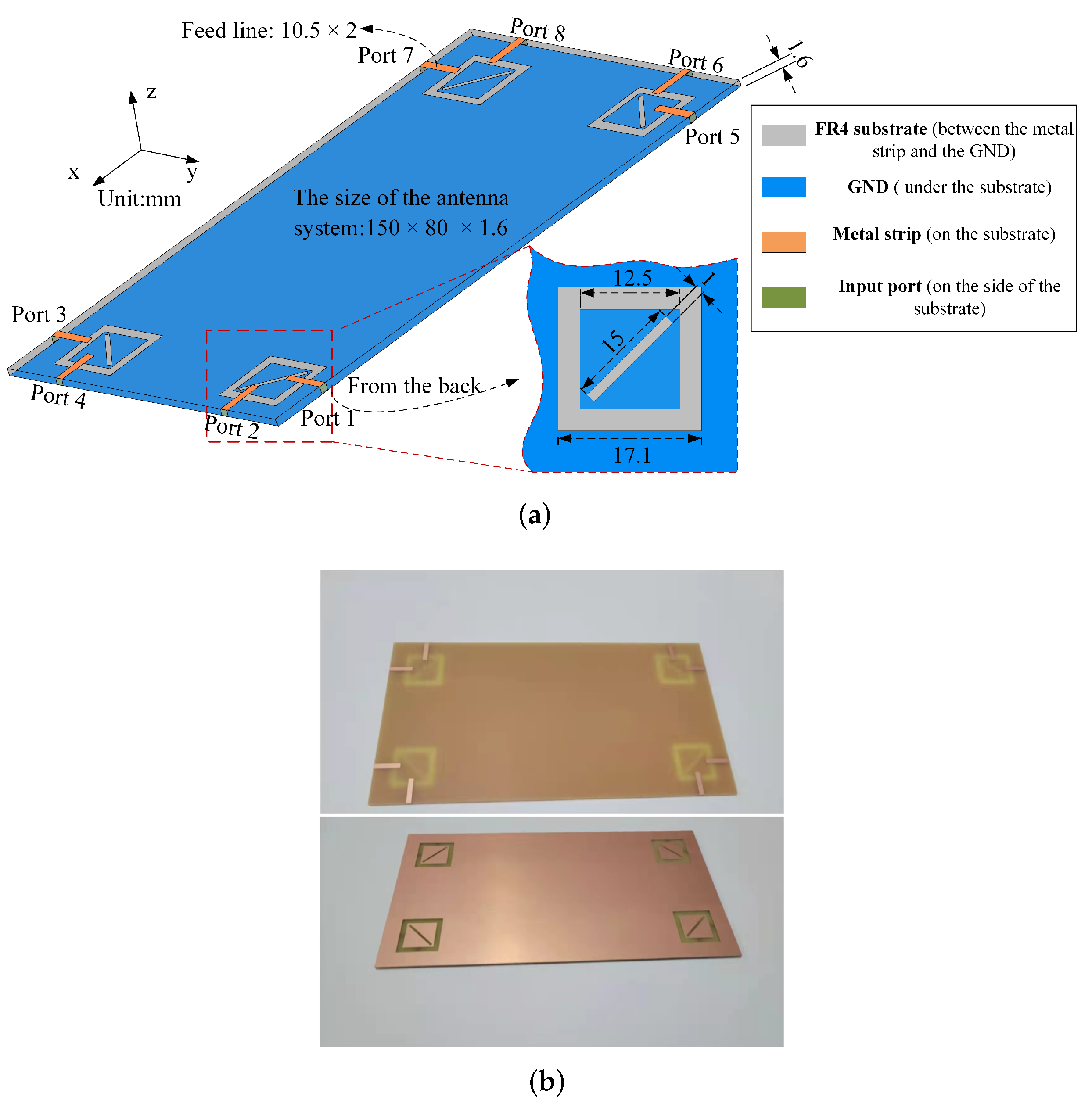
2. MIMO Antenna Structure

The structure of the proposed MIMO antenna is shown in Figure 1a. Each couple of antenna elements, which form a structure block, is placed at one of the four corners of the FR4 dielectric substrate (relative permittivity = 4.4, loss angle tangent = 0.02). The total size of the substrate is 150 × 80 × 1.6 mm 3 , and it is typically used in the 6.5-inch smartphone device. It is also known as a printed circuit board (PCB) because the feed line (orange) and ground (blue) are obtained by printing copper on the front and back of the substrate. In addition to the square loop slot, we added an diagonal slot to reduce the mutual coupling and return loss. It should be noted that all antenna elements are completely symmetrical. Unlike the structure of previous studies, which had a square copper ring engraved on the front surface of the dielectric substrate [22], the antenna in this paper has a square loop slot in the ground for radiation. The specific dimensions can be seen in Figure 1a, and special attention is paid to the diagonal slots at an angle of ±45° to the Y-axis. The square loop slot radiator on the ground plane is electromagnetic-coupling excited by two lump ports through the two microstrip lines of 2 × 10.5 mm 2 when simulating, while connecting to 50 Ω SMA connectors when measuring. Importantly, the method to feed produces a dual-polarized radiation characteristic. This characteristic is further analyzed in the fourth part. To validate this simulation, the prototype of the proposed antenna is fabricated, as shown in Figure 1b.
Each antenna element is designed to operate at the 3.5 GHz band (3.4–3.6 GHz). This is considered one of the most promising bands for 5G communication. The proposed MIMO antenna is suitable for use in modern smartphone devices.

3. Design of the Antenna Element

In this paper, the 3D full-wave electromagnetic simulation software ANSYS HFSS 2020 R1 is used for the simulated design and optimization of the antenna. As shown in Figure 2a, firstly, structure one has only a square loop slot etched in the ground (the outer length of the square loop slot is L and the inner length is S). When only one square ring slot is used as a radiator, it can be seen from Figure 2c that Ports 1 and 2 have a degree of resonance of −20 dB at 3.5 GHz, and the isolation is just under −10 dB. Then, as shown in Figure 2b, a diagonal slot is etched in the internal square rectangle, causing a sharp drop in the resonance to −43 dB (Port 1), −37 dB (Port 2), and a drop for the isolation to −14 dB. In addition, it can be seen from Figure 2d that the inclusion of the diagonal slot increases the TE of the antenna by approximately 10%, making the inclusion of the diagonal slot a sound choice.
In the process of antenna design, the parameter scan is usually performed to select the most suitable parameter. Here, three sets of scanned parameters are set up to determine the most suitable parameter by analyzing the S-parameters and the TE (Figure 3).
The first two groups are the inner and outer lengths of the square ring slot (the specific location is shown in the insertion in Figure 3a). By looking at Figure 3a–d, regardless of whether it is the inner or outer length, the smaller the size and the shorter the electrical length, the higher the resonant frequency of the antenna. In addition, the parameters S and L have a great influence on the TE, which varies non-linearly with the parameters, and different parameters correspond to different TE variation ranges. In Figure 3b, there is a 40% difference in TE at 3.6 GHz when S = 11.5 mm and S = 15 mm. Combining the resonant frequency and the TE, S = 12.5 mm and L = 17.1 mm are the most suitable choice.
The third group is the upper and lower offset shift of the feed line. As shown in Figure 3e,f, we can see that the offset of the feed line position of Port 1 changes from −2 mm to 2 mm, and the position of the feed line affects the degree of the resonance matching; however, it has little effect on the TE, and the TE changes only slightly. In the end, shift = 0 mm is chosen.
After the above analysis, we obtain the final antenna elements. Based on this, we compose an eight-port MIMO antenna, and the final simulated and measured results are given in the fifth section.

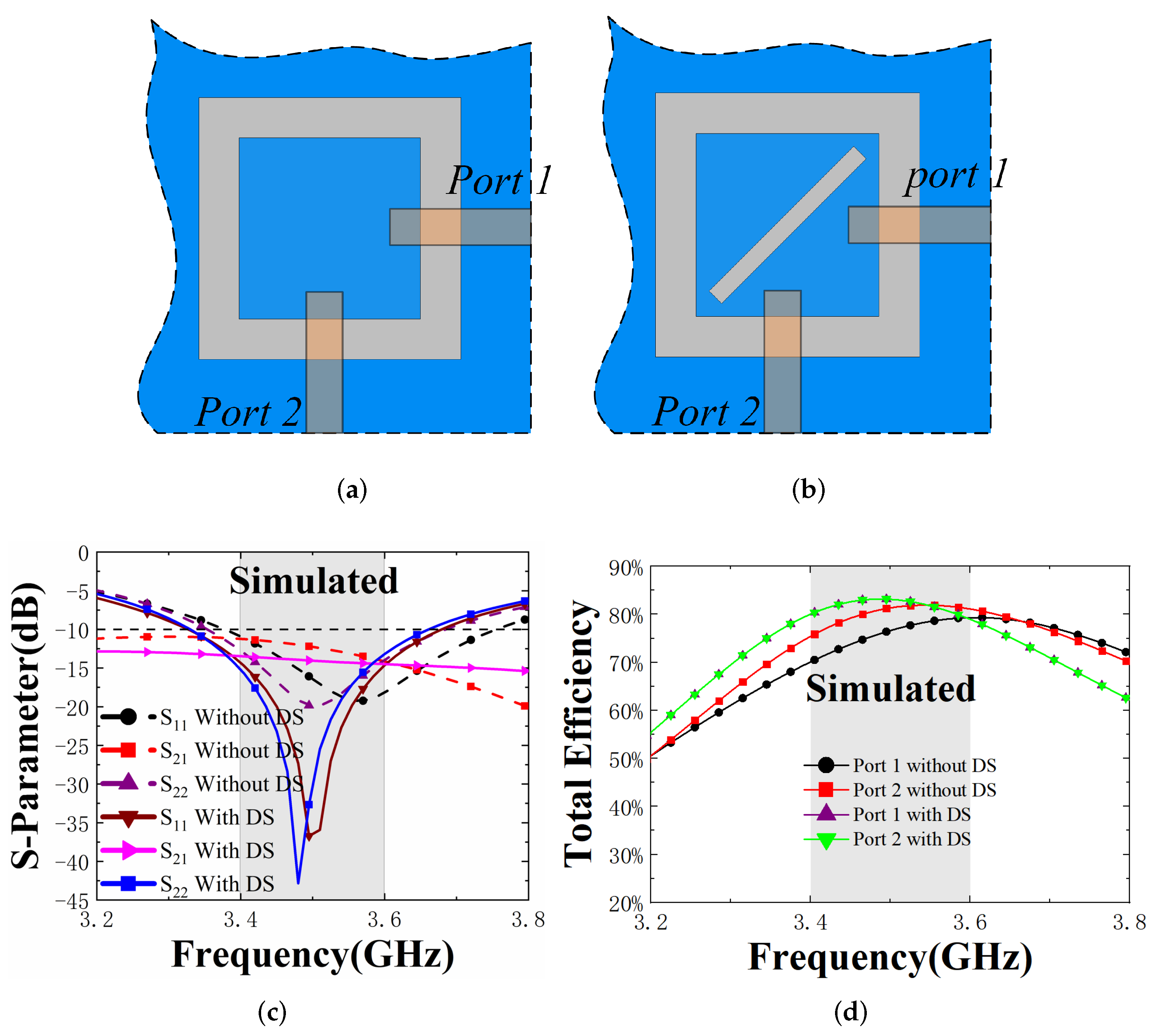
4. Working Mechanism

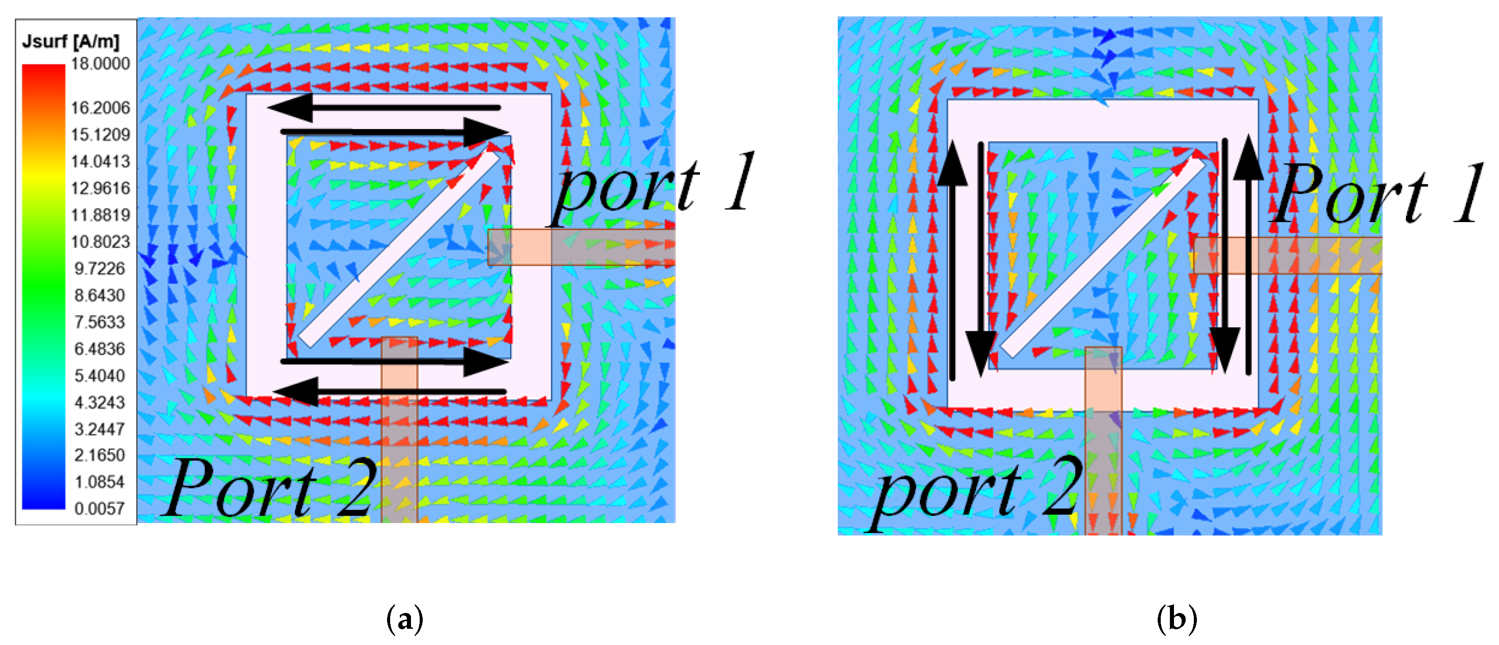
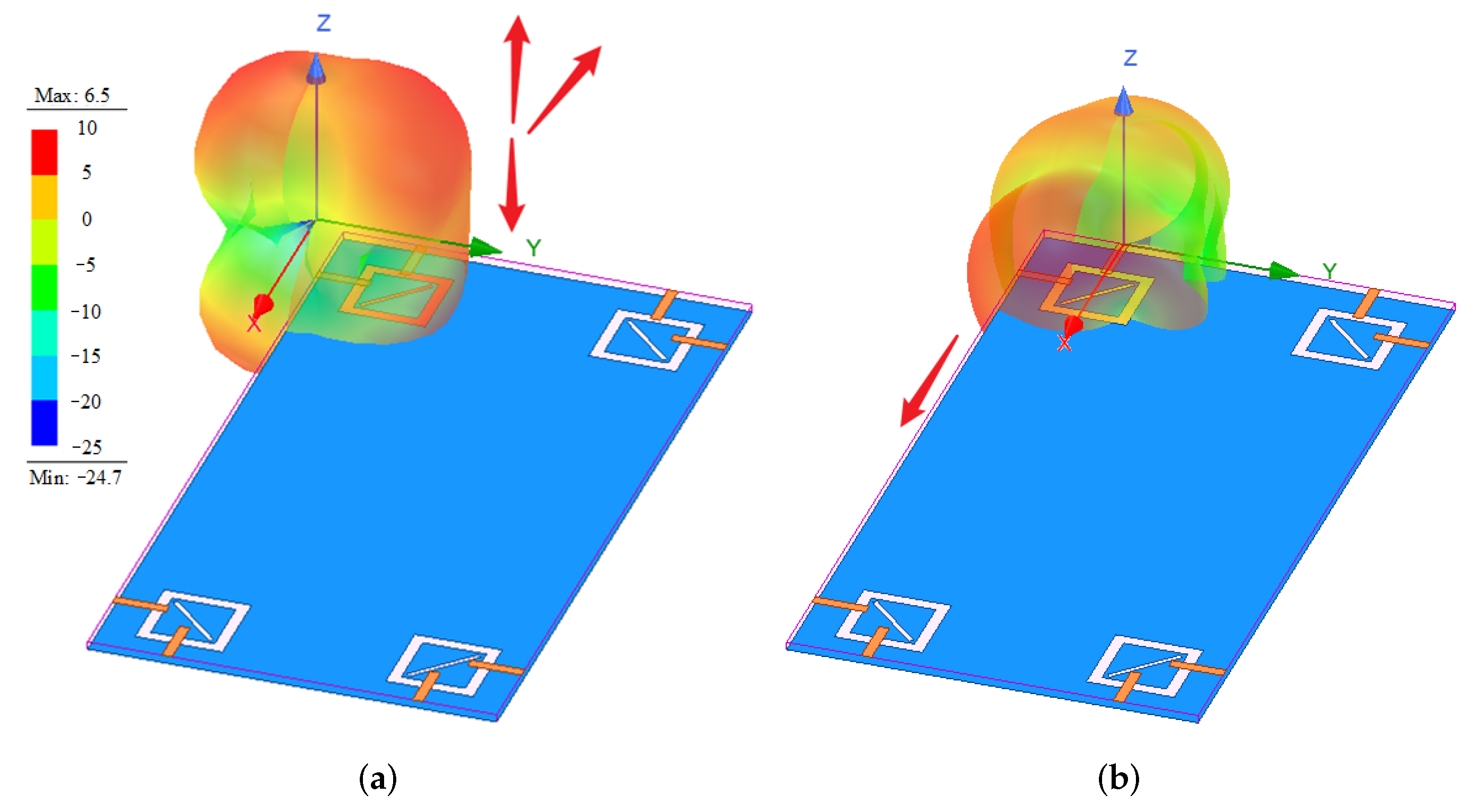
4.1. Surface Current

In order to investigate the working mechanism of the antenna, the study made observation on the surface current of the antenna and analyzed the essential reasons for the formation of the dual-polarized antenna.
As shown in Figure 4, both Ports 1 and 2 can form two slot antennas while operating individually, and their current directions are shown by the solid black arrows. In Figure 4a, it can be seen that the two slot currents are along the horizontal direction when Port 1 is excited, while being along the vertical direction when Port 2 is fed in Figure 4b. This phenomenon of orthogonal surface currents is a visual indication that the antenna has a dual polarization. To further explain the high isolation, Figure 5 gives the 3D radiation patterns generated when Ports 1 and 2 are excited separately. As can be seen from Figure 5a, when Port 1 is excited, the radiation direction is mainly in the −x-direction and ±z-direction, while when Port 2 is excited, the radiation direction is mainly +x-direction. This phenomenon indicates that the largest radiation regions are not to be crossed, thus producing high isolation (simulated isolation is better than 14 dB) without an extra decoupling structure.

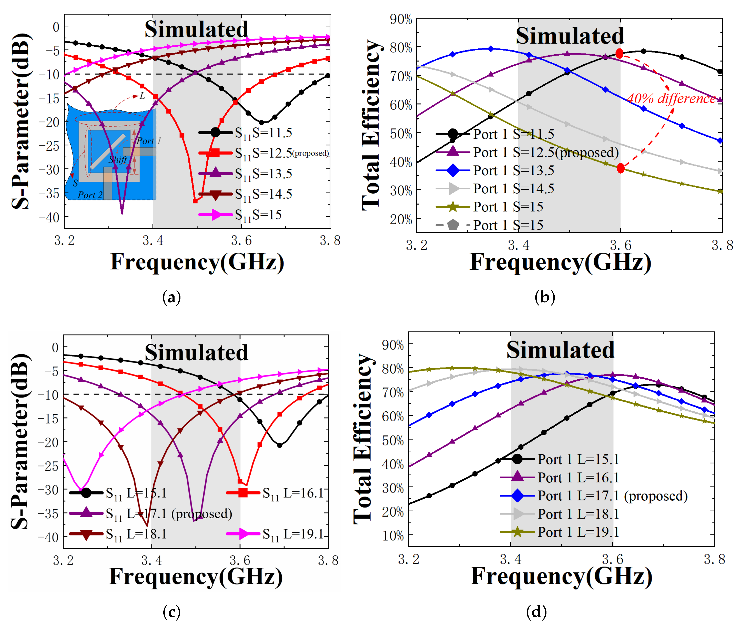
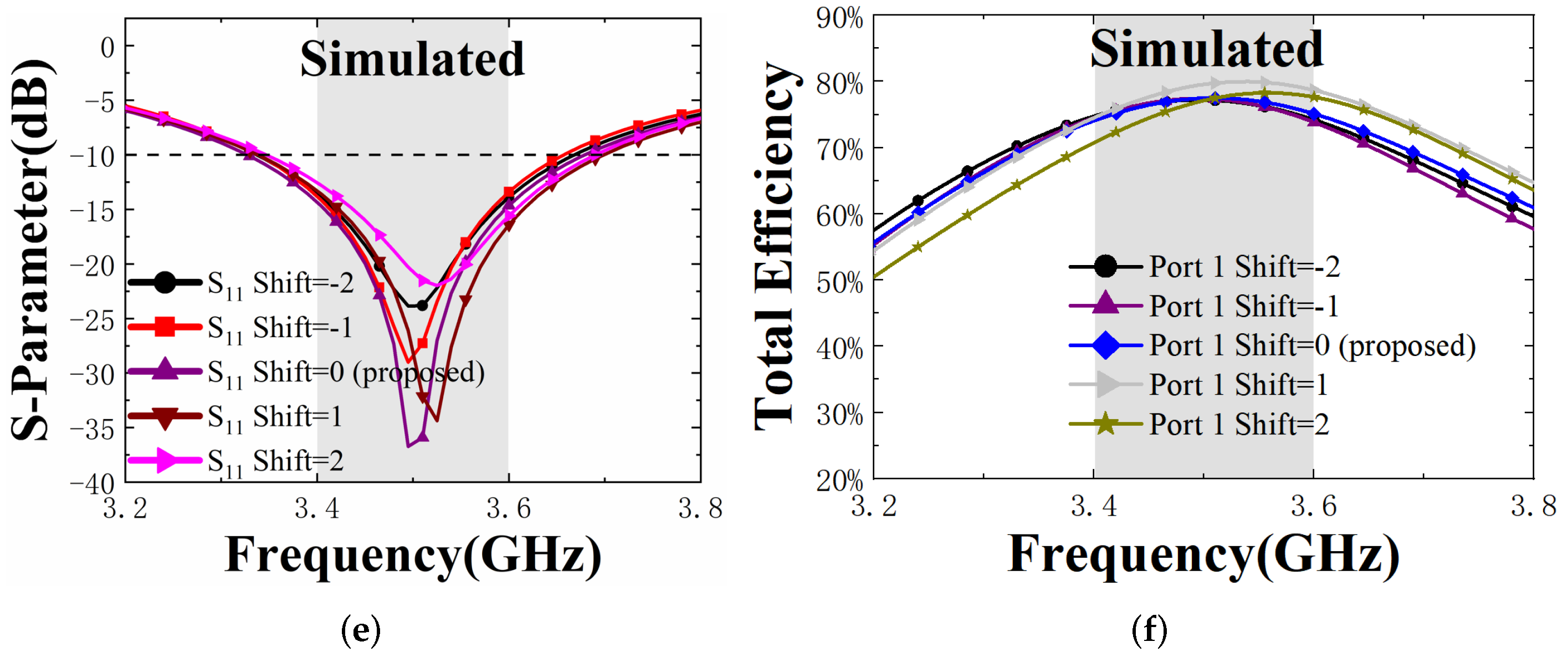
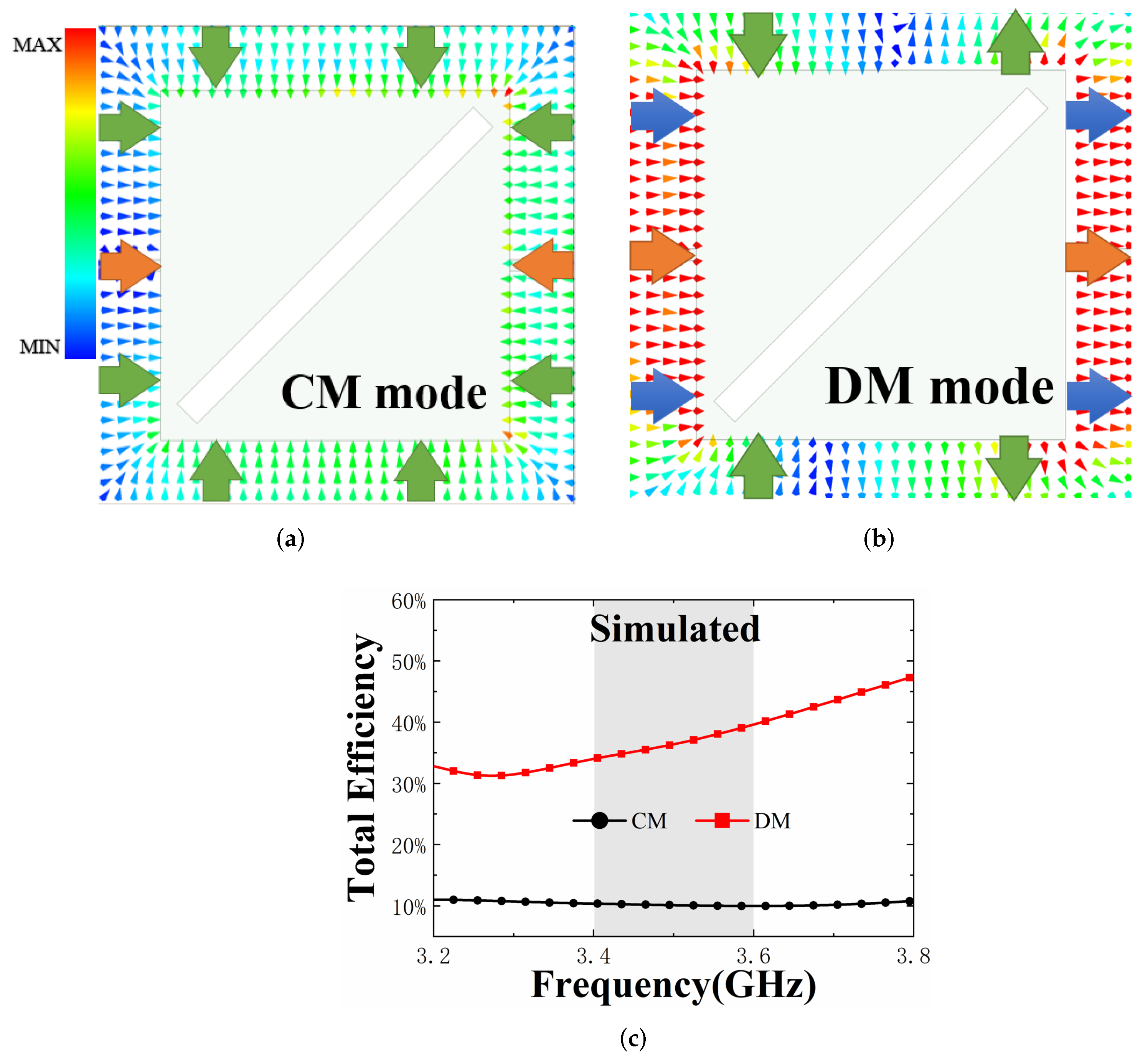
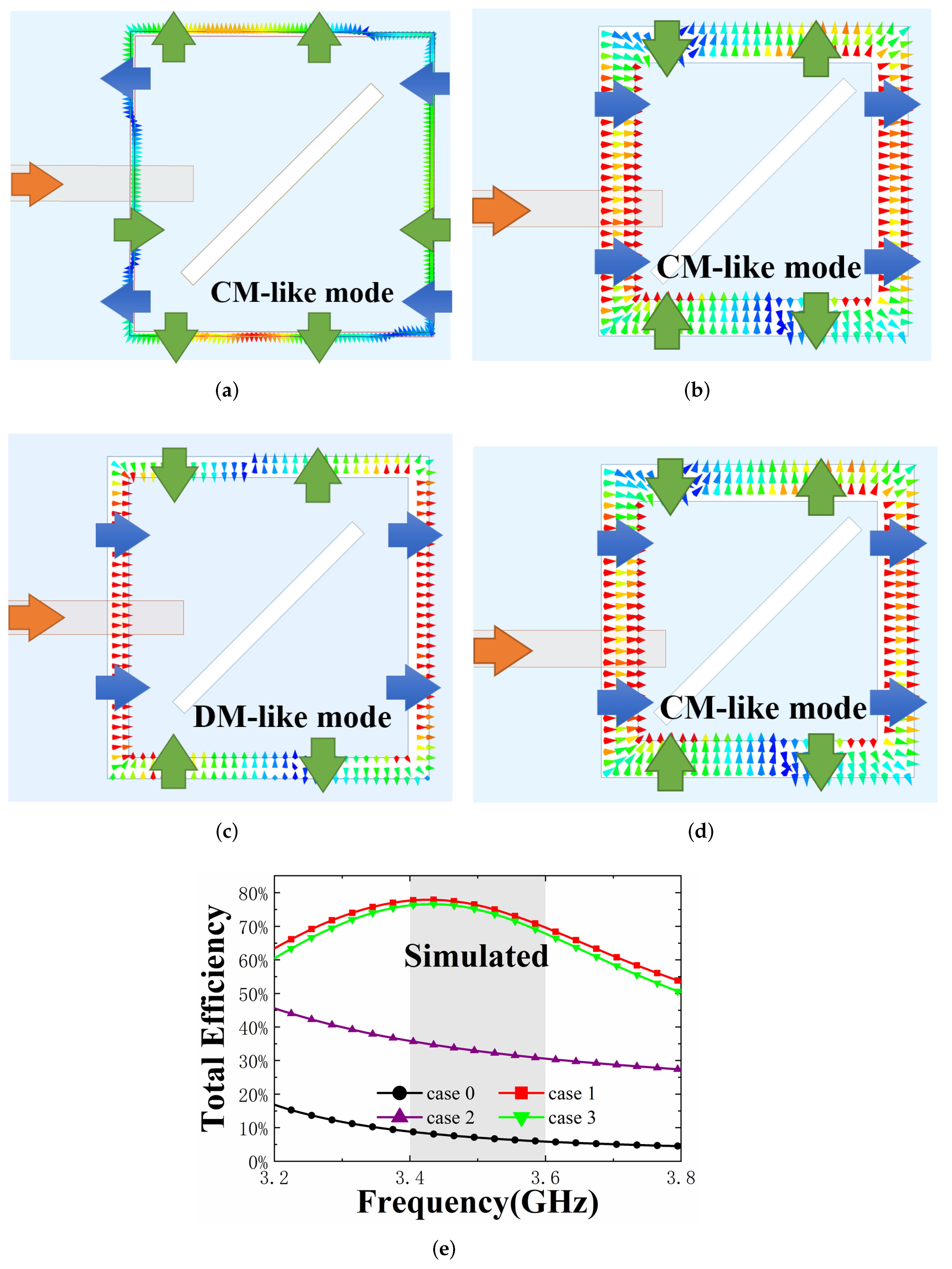
4.2. CM/DM Analysis for Total Efficiency (TE)

To explain the mechanism of how the TE is affected and the reason for the high TE, the study uses the method of CM/DM. Firstly, the antenna structure is unchanged, but the excited method is changed. Then, the study applies a pair of excitations at the square loop slot (the orange arrows in the Figure 6 represent the direction of the feed) and study the electric field distributions. It should be noted here that the DM consists of applying a pair of excitations with the same amplitude and 180 degrees out of phase, and the CM consists of applying a pair of excitations with the same amplitude and equal phase.
The electric field distributions when CM and DM are excited separately are simulated, as shown in Figure 6a,b. It is important to note here that the large green arrows represent pointing toward or away from each other, while the large blue arrows indicate pointing in the same direction. Figure 6a shows the CM excitation with the electric field distribution pointing toward the center at the same time. When excited by DM, as in Figure 6b, the electric field distribution is divided into two parts, one being the horizontal isotropic electric field, which is clearly stronger, and the other being the vertical reversely symmetrical pointing electric field. The TE of the CM/DM is shown in Figure 6c. It is obvious that the TE of the CM is lower than the DM; note that this conclusion is important and will be useful in the following analysis.
To illustrate the relationship between the CM/DM and the TE of the antenna, several different settings are chosen, and then the electric field distributions generated by Port 1 are analyzed.

4.2.1. Case 0: L = 17 mm S = 16.5 mm

As a reference system, the study sets the parameters of case 0 to have an outer side length L of 17 mm and an inner side length S of 16.5 mm for the square loop slot, respectively. As shown by the black line in Figure 7e, its TE is only 10% at the maximum, and at this point, the antenna does not radiate very well. Figure 7a gives its electric field distribution. The electric field is the strongest in the top and bottom slots, and it is distributed similarly to the electric field distribution generated when the CM is excited. Therefore, it is a CM-like mode, where it is dominated by CM with mixed CM/DM.

4.2.2. Case 1: L = 17 mm and S = 13 mm

Then, making the size S = 13 mm, according to Figure 7e, the maximum TE of the antenna is 80%. Figure 7b shows the electric field distribution. The electric field distribution of case 1 is very similar to that of DM. The strongest electric field is located on both sides, and the direction is to the right. The antenna works in a DM-like mode, where it is dominated by DM, with mixed CM/DM.

4.2.3. Case 2: L = 19 mm and S = 16.5 mm

Compared with case 0, the study makes L = 19 mm. Figure 7c shows the electric field distribution of the antenna at this time. It is obvious that the electric field distribution is like that of the DM mode, indicating that it is dominated by the DM, with the CM/DM mixing. It can be seen from the purple line in the Figure 7e that the TE of the antenna is higher than that of case 0 but lower than that of case 1.

4.2.4. Case 3: L = 17 mm, S = 13 mm with 1.5 mm Feed Line Offset

In the previous part, the influence of the feed line position on TE is given, and now the study discusses it with the electric field distribution. Figure 7d is the electric field distribution when the feed line of Port 1 offsets 1.5 mm. The electric field distribution at this time is almost the same as that in case 1, and it can be seen from Figure 7e that the TE is also very matched, which means that changing the feed line position will not affect the TE.
In summary, the TE of the proposed MIMO antenna is closely related to the electric field distribution. The change of the inner and outer side lengths of the square loop slot changes the boundary conditions, thus affecting the TE. However, the position of the feed line cannot change the effective boundary conditions, so it cannot affect the TE. In addition, the TE of the DM dominating is higher than that of the CM dominating, which corresponds to the above analysis.

5. Results and Discussion

To verify the correctness of the simulation, eight 50 Ω connectors are soldered to the feed line cable to facilitate testing. The S-parameter is tested by the Agilent E5071C vector network measurement analyzer shown in Figure 8a, and the far field parameters are obtained through the SATIMO chamber, as shown in Figure 8b.

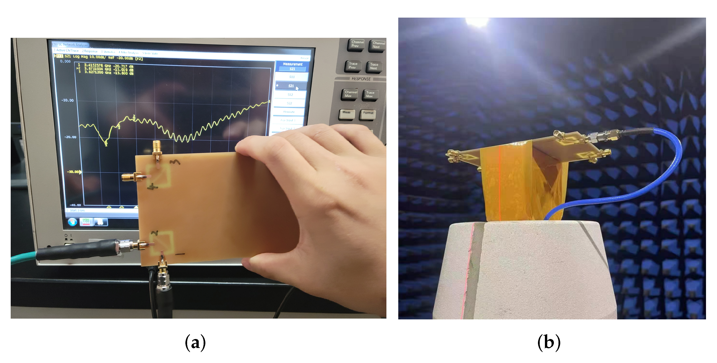
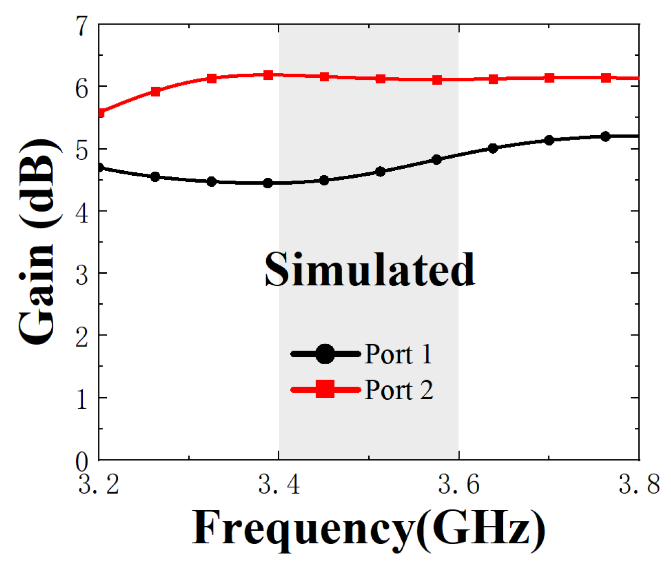
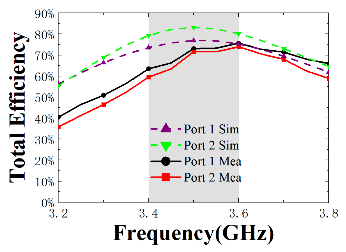
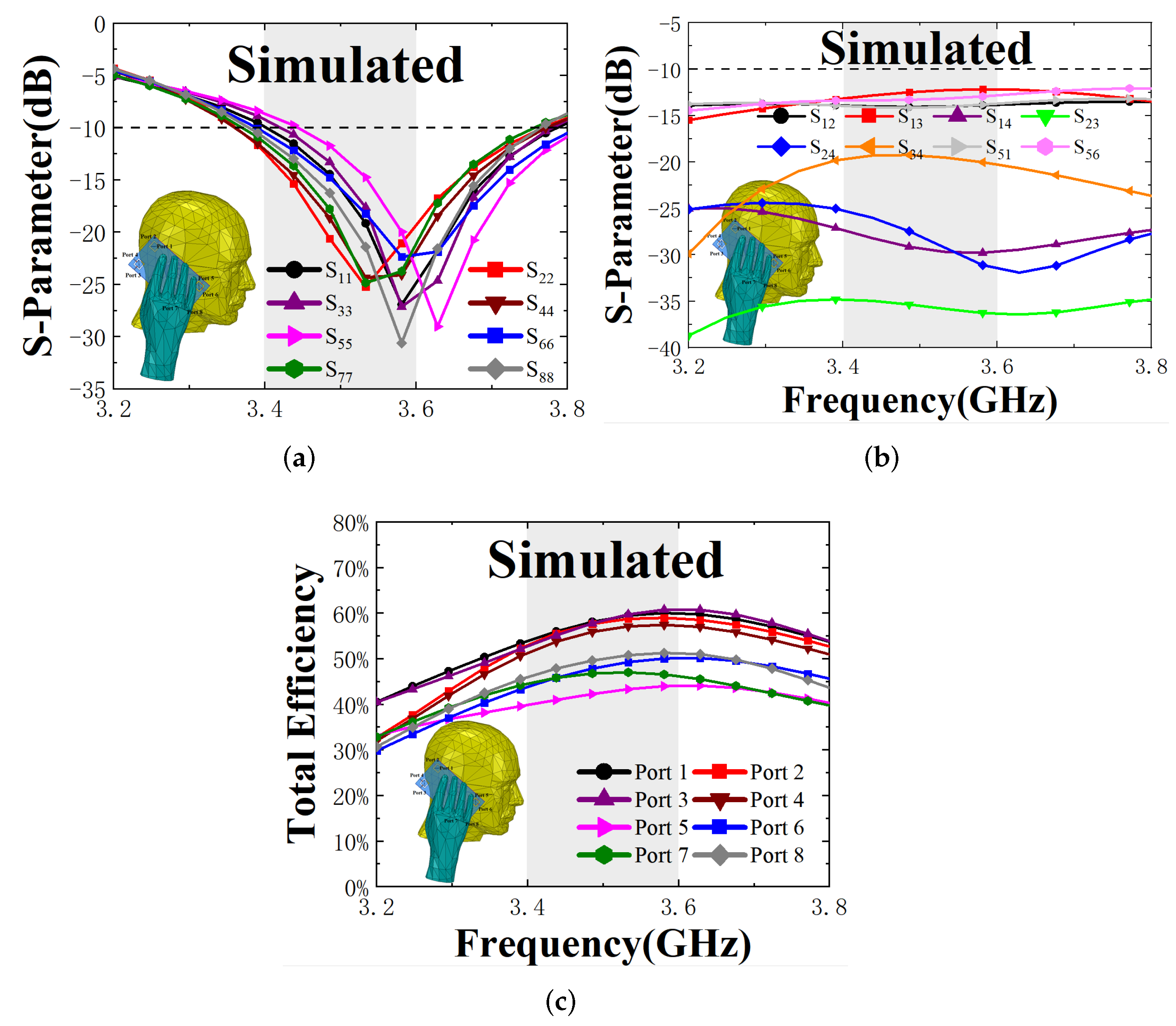
5.1. Antenna Performance

Figure 9 shows the simulated and measured S-parameters, respectively. Due to some manufacturing and welding errors, the measured data are somewhat different from the simulated data. It can be seen that the measured S 11 can cover the 3.5 GHz (3.4–3.6 GHz) frequency band. Even though the resonance degree is slightly worse than the simulated data, it also meets the requirements of the mobile phone antenna. The measured isolation is better than 17 dB. Since the resonance degree is worse than the simulated result, the measured isolation result is 3 dBi better than the simulated result, which is at the expense of the matching degree. Figure 10 shows the gain variation of the proposed antenna in the operating band, and the maximum gains of the two ports are 5.2 dB and 6.24 dB, respectively.

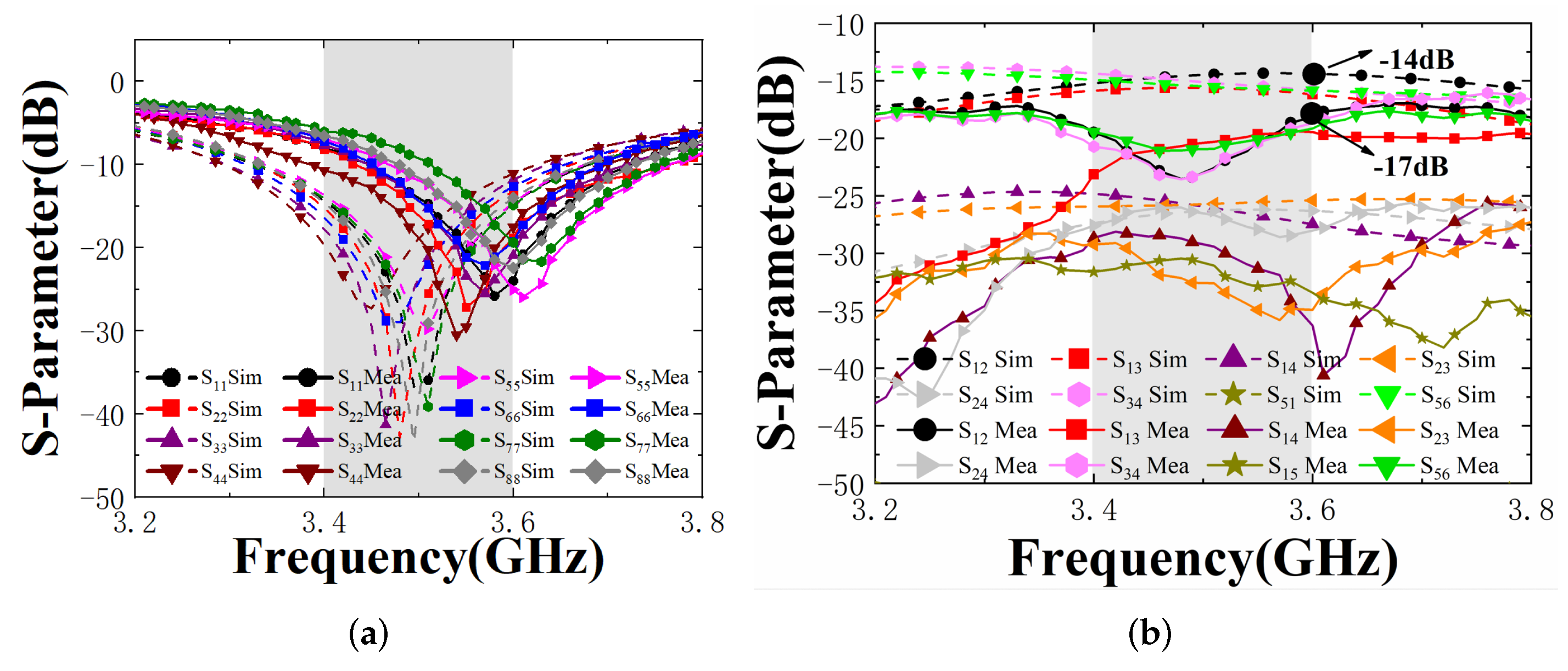
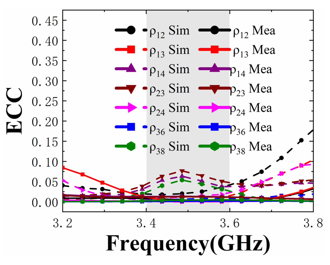
5.2. MIMO Performance

The TE results of the simulation and measurement are shown in Figure 11. It can be seen from the figure that when Ports 1 and 2 are excited, the range of the simulated TE is 75–85%, and the measured result is 60–75%. The measured TE is generally lower than the simulated, which is mainly due to the current skin effect caused by excessive solder and cavity loss.
It is important to note that the antenna does not cause any efficiency gap between individual antenna elements due to the composition of the MIMO antenna, demonstrating the good robustness of the proposed antenna.
ECC is a crucial parameter between MIMO antenna elements. ECC can be calculated by the measured S-parameter according to the following Equation (2).
E C C = | S m m * S m n + S n m * S n n | 2 / ( ( 1 ( | S m m | 2 + | S n m | 2 ) ) ( 1 ( | S n n | 2 + | S m n | 2 ) )
The results of the simulated and measured ECC are shown in Figure 12, and the measured results are basically consistent with the simulated results. All of the simulated and measured ECC is less than 0.065 in the working frequency band, which means that the eight-port MIMO antenna has good MIMO directivity.

5.3. User’s Effects on the Antenna

For the design of the terminal mobile antenna, it is indispensable to consider the effect of the user’s model on the antenna. The single hand together with the head’s influence when using the smartphone is discussed in this section.
Figure 13 show the corresponding changes of the antenna elements’ performance under the user’s model. As indicated in Figure 13a, the impedance matching of the proposed antenna is not influenced significantly due to the hands not being in contact with the antennas directly. However, the resonant points of some elements which are close to the hand model will slightly deviate from the desired 3.5 GHz, such as the S 55 , S 66 , S 77 , and S 88 . However, the isolation between antenna elements worsens, as shown in Figure 13b, which may be due to the hand and head model loading. In addition, the hand and head models can be equivalent to an irregular lossy medium, so part of the radiation power of the antenna is absorbed by the medium, resulting in a decrease in antenna efficiency, as shown in Figure 13c. Due to the absorption of the hand and head media, the TE of some antenna elements adjacent to the medium is reduced to less than 50%. It can be clearly seen from the simulated results that the MIMO antenna performance is closely related to the distance between the antenna element and the hand or head model. The closer the distance, the greater the impact on the bandwidth and efficiency. Nevertheless, the antenna elements, which are far away from the model, still have good performance.

5.4. Comparison with Others

Table 1 shows the comparison between the proposed antenna and other antennas in recent years. In the table, the sign × means that the parameter is not given in the paper. We can see that the measured isolation of the antenna is better than −17 dB without introducing extra structure for decoupling, which is higher than most antennas. In addition, the TE of the proposed antenna is 60–75%, which is also higher than other antennas, except that of [33]; however, the isolation in [33] is only 10.5 dB. Overall, the antenna presented in this paper has good characteristics compared with other antennas.

6. Conclusions

A new design of an eight-port dual-polarized high-efficiency shared-radiator MIMO antenna for 5G smartphone devices is presented along with simulated and measured results. The design is composed of four building blocks, and each building block act as a radiator consisting of a square ring slot and a diagonal slot. The design operates at 3.5 GHz (3.4 GHz–3.6 GHz) band. The simulated and measured results almost agree, except for a few changes which might have been caused due to substrate tolerance, fabrication precision and the testing setup involving the connecting cables and the connectors. In addition, the proposed antenna produces the dual polarization by placing the feed lines orthogonally, resulting in an isolation of 17 dB. This paper explains the reasons for the high total efficiency of 75% by the method of the CM/DM. As a result, the proposed antenna is well suited for the narrow frame applications and allows two shorter edges to be retained to accommodate 2G/3G/4G antennas due to the long edges of the ground which do not need to be gapped. This planar structure block is also very simple to build and easy to fabricate on FR4 substrates. As 5G will grow more rapidly in the future and the demand for various 5G devices will increase, the approach discussed in this paper provides a reference method for designing future antennas in 5G devices with both high efficiency and high isolation.

Author Contributions

Conceptualization, R.S. and X.C.; methodology, R.S., X.C. and X.W.; software, X.C. and R.S.; investigation, X.C. and R.S.; writing—original draft preparation, R.S., X.C., X.W. and J.W.; writing—review and editing, R.S., X.C. and X.W.; supervision and funding acquisition, X.W. and J.W. All authors have read and agreed to the published version of the manuscript.

Funding

This research was funded by the National Natural Science Foundation of China (Grant No. 51965047), the Natural Science Foundation of Inner Mongolia (Grant No. 2021MS06012) and the Key Scientific and Technological Project of Inner Mongolia (Grant No. 2020GG0185).

Data Availability Statement

The data presented in this study are available on request from the corresponding author.

Conflicts of Interest

The authors declare no conflict of interest.

References

  1. Dicandia, F.A.; Fonseca, N.J.G.; Bacco, M.; Mugnaini, S.; Genovesi, S. Space-Air-Ground Integrated 6G Wireless Communication Networks: A Review of Antenna Technologies and Application Scenarios. Sensors 2022, 22, 3136. [Google Scholar] [CrossRef]
  2. Lu, L.; Li, G.Y.; Swindlehurst, A.L.; Ashikhmin, A.; Zhang, R. An Overview of Massive MIMO: Benefits and Challenges. IEEE J. Sel. Top. Signal Process. 2014, 8, 742–758. [Google Scholar] [CrossRef]
  3. Dicandia, F.A.; Genovesi, S.; Monorchio, A. Analysis of the Performance Enhancement of MIMO Systems Employing Circular Polarization. IEEE Trans. Antennas Propag. 2017, 65, 4824–4835. [Google Scholar] [CrossRef]
  4. Dicandia, F.A.; Genovesi, S.; Monorchio, A. Circularly polarized MIMO antennas for wireless LAN applications. In Proceedings of the 2016 IEEE International Symposium on Antennas and Propagation (APSURSI), Fajardo, PR, USA, 26 June–1 July 2016; pp. 59–60. [Google Scholar] [CrossRef]
  5. Wang, Z.; Du, Y.; Wei, K.; Han, K.; Xu, X.; Wei, G.; Tong, W.; Zhu, P.; Ma, J.; Wang, J.; et al. Vision, application scenarios, and key technology trends for 6G mobile communications. Sci. China Inf. Sci. 2022, 65, 151301. [Google Scholar] [CrossRef]
  6. Boccardi, F.; Heath, R.W.; Lozano, A.; Marzetta, T.L.; Popovski, P. Five disruptive technology directions for 5G. IEEE Commun. Mag. 2014, 52, 74–80. [Google Scholar] [CrossRef] [Green Version]
  7. Jamshed, M.A.; Ur-Rehman, M.; Frnda, J.; Althuwayb, A.A.; Nauman, A.; Cengiz, K. Dual Band and Dual Diversity Four-Element MIMO Dipole for 5G Handsets. Sensors 2021, 21, 767. [Google Scholar] [CrossRef]
  8. Nadeem, I.; Alibakhshikenari, M.; Babaeian, F.; Althuwayb, A.; Virdee, B.S.; Azpilicueta, L.; Khan, S.; Huynen, I.; Falcone, F.J.; Denidni, T.A.; et al. A comprehensive survey on ‘circular polarized antennas’ for existing and emerging wireless communication technologies. J. Phys. D Appl. Phys. 2022, 55, 033002. [Google Scholar] [CrossRef]
  9. You, C.; Jung, D.; Song, M.; Wong, K.L. Advanced 12 × 12 MIMO Antennas for Next Generation 5G Smartphones. In Proceedings of the 2019 IEEE International Symposium on Antennas and Propagation and USNC-URSI Radio Science Meeting, Atlanta, GA, USA, 7–12 July 2019. [Google Scholar]
  10. Wong, K.L.; Tsai, C.Y.; Lu, J.Y. Two Asymmetrically Mirrored Gap-Coupled Loop Antennas as a Compact Building Block for Eight-Antenna MIMO Array in the Future Smartphone. Antennas Propag. IEEE Trans. 2017, 65, 1765–1778. [Google Scholar] [CrossRef]
  11. Ban, Y.L.; Li, C.; Sim, C.; Wu, G.; Wong, K.L. 4G/5G Multiple Antennas for Future Multi-Mode Smartphone Applications. IEEE Access 2017, 4, 2981–2988. [Google Scholar] [CrossRef]
  12. Biglieri, E.; Calderbank, R.; Constantinides, A.; Goldsmith, A.; Poor, H.V. MIMO Wireless Communications; Cambridge University Press: Cambridge, UK, 2007. [Google Scholar]
  13. Mak, A.; Rowell, C.R.; Murch, R.D. Isolation Enhancement between Two Closely Packed Antennas. IEEE Trans. Antennas Propag. 2008, 56, 3411–3419. [Google Scholar] [CrossRef]
  14. Tran, H.H.; Nguyen-Trong, N. Performance Enhancement of MIMO Patch Antenna Using Parasitic Elements. IEEE Access 2021, 9, 30011–30016. [Google Scholar] [CrossRef]
  15. Diallo, A.; Luxey, C.; Le Thuc, P.; Staraj, R.; Kossiavas, G. Study and Reduction of the Mutual Coupling between Two Mobile Phone PIFAs Operating in the DCS1800 and UMTS Bands. IEEE Trans. Antennas Propag. 2006, 54, 3063–3074. [Google Scholar] [CrossRef]
  16. Su, S.W.; Lee, C.T.; Chang, F.S. Printed MIMO-Antenna System Using Neutralization-Line Technique for Wireless USB-Dongle Applications. IEEE Trans. Antennas Propag. 2012, 60, 456–463. [Google Scholar] [CrossRef]
  17. Jiang, W.; Liu, B.; Cui, Y.; Hu, W. High-Isolation Eight-Element MIMO Array for 5G Smartphone Applications. IEEE Access 2019, 7, 34104–34112. [Google Scholar] [CrossRef]
  18. Luo, C.M.; Hong, J.S.; Zhong, L.L. Isolation Enhancement of a Very Compact UWB-MIMO Slot Antenna with Two Defected Ground Structures. IEEE Antennas Wirel. Propag. Lett. 2015, 14, 1766–1769. [Google Scholar] [CrossRef]
  19. Yuan, X.T.; He, W.; Hong, K.D.; Han, C.Z.; Chen, Z.; Yuan, T. Ultra-Wideband MIMO Antenna System with High Element-Isolation for 5G Smartphone Application. IEEE Access 2020, 8, 56281–56289. [Google Scholar] [CrossRef]
  20. Lee, Y.; Ga, D.; Choi, J. Design of a MIMO Antenna with Improved Isolation Using MNG Metamaterial. Int. J. Antennas Propag. 2012, 2012, 231–234. [Google Scholar] [CrossRef] [Green Version]
  21. Li, M.; Jamal, M.Y.; Jiang, L.; Yeung, K.L. Isolation Enhancement for MIMO Patch Antennas Sharing a Common Thick Substrate: Using a Dielectric Block to Control Space-Wave Coupling to Cancel Surface-Wave Coupling. IEEE Trans. Antennas Propag. 2021, 69, 1853–1863. [Google Scholar] [CrossRef]
  22. Li, M.Y.; Xu, Z.Q.; Ban, Y.L.; Sim, C.; Yu, Z.F. Eight-port Orthogonally Dual-Polarized MIMO Antennas Using Loop Structures for 5G Smartphone. Iet Microw. Antennas Propag. 2017, 11, 1810–1816. [Google Scholar] [CrossRef]
  23. Li, Y.; Sim, C.Y.D.; Luo, Y.; Yang, G. High-Isolation 3.5 GHz Eight-Antenna MIMO Array Using Balanced Open-Slot Antenna Element for 5G Smartphones. IEEE Trans. Antennas Propag. 2019, 67, 3820–3830. [Google Scholar] [CrossRef]
  24. Cheng, B.; Du, Z. Dual Polarization MIMO Antenna for 5G Mobile Phone Applications. IEEE Trans. Antennas Propag. 2021, 69, 4160–4165. [Google Scholar] [CrossRef]
  25. Jamal, M.Y.; Li, M.; Yeung, K.L. Isolation Enhancement of Closely Packed Dual Circularly Polarized MIMO Antenna Using Hybrid Technique. IEEE Access 2020, 8, 11241–11247. [Google Scholar] [CrossRef]
  26. Zhao, X.; Yeo, S.P.; Ong, L.C. Decoupling of Inverted-F Antennas with High-Order Modes of Ground Plane for 5G Mobile MIMO Platform. IEEE Trans. Antennas Propag. 2018, 66, 4485–4495. [Google Scholar] [CrossRef]
  27. Xu, H.; Zhou, H.; Gao, S.; Wang, H.; Cheng, Y. Multimode Decoupling Technique with Independent Tuning Characteristic for Mobile Terminals. IEEE Trans. Antennas Propag. 2017, 65, 6739–6751. [Google Scholar] [CrossRef]
  28. Ren, Z.; Zhao, A.; Wu, S. MIMO Antenna with Compact Decoupled Antenna Pairs for 5G Mobile Terminals. IEEE Antennas Wirel. Propag. Lett. 2019, 18, 1367–1371. [Google Scholar] [CrossRef]
  29. Deng, C.; Liu, D.; Lv, X. Tightly Arranged Four-Element MIMO Antennas for 5G Mobile Terminals. IEEE Trans. Antennas Propag. 2019, 67, 6353–6361. [Google Scholar] [CrossRef]
  30. Chang, L.; Yu, Y.; Wei, K.; Wang, H. Polarization-Orthogonal Co-frequency Dual Antenna Pair Suitable for 5G MIMO Smartphone with Metallic Bezels. IEEE Trans. Antennas Propag. 2019, 67, 5212–5220. [Google Scholar] [CrossRef]
  31. Ren, A.; Liu, Y.; Sim, C. A Compact Building Block with Two Shared-Aperture Antennas for Eight-Antenna MIMO Array in Metal-Rimmed Smartphone. IEEE Trans. Antennas Propag. 2019, 67, 6430–6438. [Google Scholar] [CrossRef]
  32. Yang, B.; Xu, Y.; Tong, J.; Zhang, Y.; Feng, Y.; Hu, Y. Tri-port Antenna with Shared Radiator and Self-decoupling Characteristic for 5G Smartphone Applications. IEEE Trans. Antennas Propag. 2021, in press. [CrossRef]
  33. Sun, L.; Li, Y.; Zhang, Z.; Wang, H. Self-Decoupled MIMO Antenna Pair with Shared Radiator for 5G Smartphones. IEEE Trans. Antennas Propag. 2020, 68, 3423–3432. [Google Scholar] [CrossRef]
  34. Li, R.; McNamara, D.; Wei, G.; Li, J. Increasing Radiation Efficiency Using Antenna Shape Optimization Approach. IEEE Antennas Wirel. Propag. Lett. 2018, 17, 393–396. [Google Scholar] [CrossRef]
  35. Liu, K.; Yu, D.; Wang, H. Investigation on the Radiation Efficiency Local Minimum in Open-Slot and T-Shaped Antennas. IEEE Trans. Antennas Propag. 2021, 69, 5257–5268. [Google Scholar] [CrossRef]
Figure 1. Configuration, dimensions, and photograph of the proposed eight-port antenna MIMO antenna. (a) Antenna configuration. (b) Photograph of the fabricated proposed antenna prototype.
Electronics 11 01628 g001
Figure 2. Evolution steps of the proposed elements. (a) Without diagonal slot. (b) With diagonal slot. (c) Simulated S-Parameter. (d) Simulated TE.
Electronics 11 01628 g002
Figure 3. Simulated results of the proposed antenna for different values. (a) S-parameter for different S. (b) TE for different S. (c) S-parameter for different L.(d) TE for different L. (e) S-parameter for different Shift. (f) TE for different Shift.
Electronics 11 01628 g003aElectronics 11 01628 g003b
Figure 4. The surface current distributions of the proposed antenna element at 3.5 GHz. (a) Port 1. (b) Port 2.
Electronics 11 01628 g004
Figure 5. 3D radiation patterns of the proposed antenna at 3.5 GHz. (a) Port 1. (b) Port 2.
Electronics 11 01628 g005
Figure 6. Electric field distribution of the square loop slot at (a) CM mode. (b) DM mode. (c) TE of the two mode.
Electronics 11 01628 g006
Figure 7. Electric field distribution of the proposed antenna at (a) case 0. (b) case 1. (c) case 2.(d) case 3. (e) TE.
Electronics 11 01628 g007
Figure 8. Photograph of (a) test use of the vector network measurement analyzer. (b) Test in the anechoic chamber.
Electronics 11 01628 g008
Figure 9. Simulated and measured S-parameter of the proposed antenna. (a) Reflection coefficients. (b) Transmission coefficients.
Electronics 11 01628 g009
Figure 10. Gain of the proposed antenna.
Electronics 11 01628 g010
Figure 11. Simulated and measured TE of the proposed antenna.
Electronics 11 01628 g011
Figure 12. Simulated and measured ECC of the proposed antenna.
Electronics 11 01628 g012
Figure 13. Simulated results of the proposed antenna with single hand and head model. (a) Reflection coefficients. (b) Transmission coefficients. (c) Total efficiency.
Electronics 11 01628 g013
Table 1. Performance comparison with other smartphone MIMO antennas.
RefDecoupling MethodWorking Band (GHz)Isolation (dB)TE (%)ECCComplexity
[17]NL3.3–3.615>400.15Simple
[19]DGS3.3–618>400.05Mdeium
[23]Polarisation diversity3.4–3.617.5>620.05Simple
[24]Orthogonal polarization4.4–52240–500.068Complex
[28]Self-decoupled3.4–3.617×0.1Simple
[29]LC tank3.4–3.611.647–51×Medium
[30]Orthogonal mode3.4–3.612.735.2–64.70.13Complex
[31]Self-decoupled3.4–3.61659–730.05Medium
[32]CM/DM3.4–3.61151–710.14Medium
[33]CM/DM3.3–4.310.563.1–85.1×Simple
This workOrthogonal polarization3.4–3.61760–750.045Simple
Publisher’s Note: MDPI stays neutral with regard to jurisdictional claims in published maps and institutional affiliations.

