Article

Analysis of a User Interface Based on Multimodal Interaction to Control a Robotic Arm for EOD Applications

Department of Electronic Engineering, Universidad Nacional de San Agustín de Arequipa, Arequipa 04001, Peru
*
Authors to whom correspondence should be addressed.
These authors contributed equally to this work.
Submission received: 16 March 2022 / Revised: 5 April 2022 / Accepted: 6 April 2022 / Published: 25 May 2022
(This article belongs to the Special Issue Physical Human-Robot Interaction and Robot Manipulation)

Abstract

:
A global human–robot interface that meets the needs of Technical Explosive Ordnance Disposal Specialists (TEDAX) for the manipulation of a robotic arm is of utmost importance to make the task of handling explosives safer, more intuitive and also provide high usability and efficiency. This paper aims to evaluate the performance of a multimodal system for a robotic arm that is based on Natural User Interface (NUI) and Graphical User Interface (GUI). The mentioned interfaces are compared to determine the best configuration for the control of the robotic arm in Explosive Ordnance Disposal (EOD) applications and to improve the user experience of TEDAX agents. Tests were conducted with the support of police agents Explosive Ordnance Disposal Unit-Arequipa (UDEX-AQP), who evaluated the developed interfaces to find a more intuitive system that generates the least stress load to the operator, resulting that our proposed multimodal interface presents better results compared to traditional interfaces. The evaluation of the laboratory experiences was based on measuring the workload and usability of each interface evaluated.

Graphical Abstract

1. Introduction

Worldwide, EOD (Explosive Ordnance Disposal) robots are used to support agents who deactivate explosives. The studies carried out on the interventions of the UDEX—AQP, in the period 2013 to 2020, show that an EOD robot would have had an efficient participation of 91% of the cases in deactivation of explosives. Likewise, 47% of the most recurrent explosive devices were grenades and dynamites [1]. Due to the complexity of the operation, the life of the TEDAX agents is constantly at risk in the actual procedures of explosive ordnance disposal. Therefore, an intuitive and user-friendly interface for handling an EOD robot with higher efficiency and performance is important to provide the most information to the TEDAX agent, that is a control interface with higher performance is relevant for these operation applications.
Humans interact mainly with the world through their five senses: sight, hearing, touch, smell and taste. The mode of communication with the robot is through an interface that allows interaction between the user and the equipment to be controlled, and interfaces are an important part of human–robot interaction (HRI). The field of HRI addresses the design, understanding, and evaluation of robotic systems, which involve humans and robots interacting through communication [2]. The HRI is designed to provide a complete environment for robotic interventions, including preparation, training, operation, and post-data analysis. The main function of the HRI is to guarantee the user to have a good reciprocal relationship between the person and the robot, to maintain a good communication, through the interfaces, which is the main way for the user to interact with the robot [3]. It should also include advanced features to increase safety, intervention and tele-presence of the operator [4]. To realize and evaluate robot manipulation interfaces, it is not sufficient to simply focus on providing detailed and comprehensive control capability; ease of use must always be an integral priority. Interfaces must be able to support the needs of users and help them complete the desired aim [5]. An interface that enables effective human–robot interaction is multimodal interfaces, as it allows the user to interact with the environment in a natural way; since it usually includes interfaces based on voice, motion, and gestures of the human person [6].
Currently, interfaces must work with more than one system for best results, these types of interfaces are known as multimodal interfaces. Multimodal interfaces describe interactive systems that take advantage of natural human abilities to communicate through gestures, touch, facial expression, and other modalities, using classification and pattern recognition methods more sophisticated than human–computer interaction. The goal of the multimodal interfaces research area is to develop technologies, interaction methods and interfaces to make full use of human capabilities for good immersion [7]. For the design of multimodal interfaces, several options of existing modalities, channels, and devices are presented for multimodal interaction applied to many of the well-known interfaces [8]. Remote communication technologies such as WSN (Wireless Sensor Network) are applicable for environmental monitoring, health, and citizen security [9], and these types of technologies can be associated for the design of a multimodal interface with higher performance in situations where sta-remote control functions to manipulate some equipment wirelessly.
According to [10], for the design of multimodal systems, the following must be considered: the use of the multimodal interface is for a wide range of users, determine the configuration of the interface (for a destination or purpose), maximize the mental and physical capacity immersed in the operation; and provide good error prevention and handling. The main advantages of using multimodal systems can be found in other aspects, such as the reduction of errors, the increase in flexibility or the increase in user satisfaction.
A gesture-based interface presents a potential alternative for the design of a multimodal interface, as it is the most primary and expressive form of human communication [11]. There are several ways to design a multimodal interface starting from simple interfaces, for example in [12], several NUI interfaces (Natural User Interface) and GUI interfaces (Graphical User Interface) are studied and implemented for the intuitive and natural control of drones, the developed NUI interfaces are: Visual, Hand gesture and Voice, in addition, there is a control station that essentially includes the NUI interface. In [13], the intermodal interface of vision, audio and haptic sensors for rescue and security EOD robots is developed. In [4], the presented HRI is a novel research contribution in terms of multimodality, adaptability and modularity for robotic teams of mobile manipulators in radioactive environments, an interface designed in a modular way is proposed, to guarantee its adaptability to new robots and tasks, and multimodal, to provide high usability and efficiency even in multi-agent scenarios.
There are several intuitive interfaces such as the NUI interface, which makes it possible to imitate the way in which a person expresses him/herself, through body gestures, providing the possibility that human–robot interaction is by direct command and interaction through gestures as mirror imitation [14]. Recently Leap Motion sensor has been widely used in natural gesture recognition applications [15,16,17], this sensor can accurately recognize hand gestures, especially thumb movement, so it can be used as an intuitive interface to manipulate a robotic arm by being able to replicate the movement of the hand, for this reason this sensor can be considered as a NUI interface. In [18], the use of an interface based on control by gestures together with an interface by buttons is evaluated, where they provide good results from the point of view of temporary demand load and total workload, then the use of NUI interface for robotic arms in EOD applications. In [19], the presence of noise in the Leap Motion sensor is highlighted, which translates into errors in a hand position tracking application that increases over time. In order to overcome this deficiency, the use of the Kalman filter is proposed to minimize the noise of this sensor and guarantee a good precision.
In [20], a stereo vision system used in Robot Soccer systems is described in a general way. First, the positioning of the cameras, cameras in parallel configuration, which are used in a robotic soccer system for both FIRA (Federation of International Robot-soccer) and RoboCup, is listed, the image processing algorithms are explained and the reference related to its advantages and disadvantages, some of them being Kalman Filter, CAMSHIFT(Continuously Adaptive Mean Shift) and Optical Flow. For the particular case of stereo vision, the distance is estimated with the stereo calibration of the cameras, the intrinsic and extrinsic parameters of the cameras are obtained and the distance of the objects captured in both cameras is calculated. In [21], a system that controls a robotic arm to grab an object through stereo vision in parallel configuration and fixed camera is developed. In addition, object tracking is achieved thanks to distance estimation through the Triangulation method. The system is checked with some operations described in the document. In [22], it also incorporates the Triangulation method, through a stereo vision system, which grabs an object by means of a robotic arm, which uses the CAMSHIFT and ANFIS algorithms that provide better tracking.
In the present work, multimodal interfaces are analyzed to be applicable in EOD robots. The main interface analyzed is composed of the NUI interface based on the Leap Motion gesture recognition sensor and a visual interface based on computer vision to automatically move the robotic arm towards a target. An integration and comparison of GUI, NUI and visual interfaces is developed to determine the best way to manipulate robotic arms in EOD applications in relation to performance, ease and use. In Section 2, we detail the composition of the different interfaces developed such as the Visual Interface, NUI and GUI. Section 4 defines the experimentation, defining the multimodal configurations as the testing protocol and the evaluation methodology applied. The interfaces are compared in three different configurations and are evaluated from the point of view of usability and user experience using the SUS (System usability scale) [23] and NASA-TLX (NASA task load index) [24,25] evaluation methods, in order to establish the possibility and form of use for EOD operations. In Section 5, the results of the evaluation tests applied and the interpretation and analysis of the results are presented. In Section 5, conclusions and future work that our research can approach are presented.

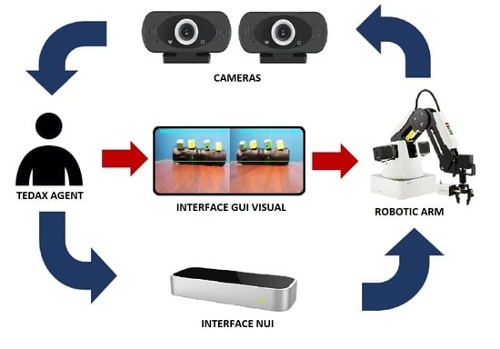
2. Composition of the Interface System

Each interface to be analyzed (see Figure 1) was developed in previous works [18,26]. These interfaces are as follows:
  • Visual interface: It consists of 2 stereo cameras and their graphical interface for the selection of a target through the control station display [26]. By means of this interface, the automatic approach of the final actuator of the robotic arm to the selected target is performed, thus providing a better way to control the robotic arm.
  • NUI Interface: The interface is conformed by the Leap Motion sensor that allows recognizing the palm of the hand. It has an algorithm that is composed of the sensor SDK with the Kalman filter that will help to decrease the hand tracking error and optimizing the control of the robotic arm [18]. This allows manipulating the robotic arm by replicating the movements made by the person with his hand towards the robotic arm.
  • GUI interface: This interface is based on control buttons that achieve the movement of the robotic arm for each degree of freedom (DOF) providing the control of the robotic arm towards a desired position of the end efector.

2.1. Proposed Multimodal System

In this section, the proposed multimodal system is shown, and the algorithms used and the hardware components necessary for its development are detailed.

2.1.1. Natural User Interface (NUI)

The NUI interface is based on the Leap Motion sensor, which is a sensor that recognizes hand gestures through monochrome cameras and infrared sensors. In the development of the interface, a Kalman filter was used in order to reduce the inherent noise of the sensor and the tracking errors to more accurately estimate the position of the human hand. The development of the NUI interface algorithm is presented below. To consider the same reference system, a world coordinate system is used. The implementation of the coordinate register is detailed below. The world coordinates X W Y W Z W located at the base of the robot Dobot Magician (Figure 2), where X L Y L Z L and X H Y H Z H represent Leap Motion sensor and hand coordinate systems, respectively.
The Leap Motion sensor can build a virtual human skeleton model where the center of the palm is defined as center X H Y H Z H , shown in detail in (Figure 2). Through the reference change, a position of X H Y H Z H is converted into coordinate X L Y L Z L through:
[ P X L , P Y L , P Z L ] = T H 2 L [ P X H , P Y H , P Z H ]
where [ P X H , P Y H , P Z H ] represents the position of any point of the hand in the system X H Y H Z H ; T H 2 L represents the homogeneous transformation matrix from X H Y H Z H to X L Y L Z L . Then, [ P X L , P Y L , P Z L ] in the system X L Y L Z L can be transferred to the following position in the world coordinate:
[ P X W , P Y W , P Z W ] = T L 2 W [ P X L , P Y L , P Z L ]
Based on the reference shift Equations (1) and (2), the position of [ P X H , P Y H , P Z H ] can be transformed into the world frame coordinate system as a homogeneous matrix:
P = [ P X W , P Y W , P Z W ] = T L 2 W T H 2 L [ P X H , P Y H , P Z H ]
= T H 2 W L H 2 W 0 1 [ P X W , P Y W , P Z W ] T
where T H 2 W is the transformation matrix from the hand coordinate system to the world, consisting of a rotation matrix M H 2 W and a translation matrix L H 2 W . The rotation matrix M H 2 W is represented by:
M H 2 W , k = m X x , k m Y x , k m Z x , k m X y , k m Y y , k m Z y , k m X z , k m Y z , k m Z z , k
where m i j k = c o s ( θ i j ) ; θ i j ( i , j ϵ ( x , y , z ) ) means the angle between the i-axis at the hand coordinate and the j-axis at the world coordinate. In the world coordinate system, p k + 1 denotes the position of the hand at time t k + 1 , and this is calculated as:
p k + 1 = p k + v k t + 1 2 a k t 2
where p k , v k , and a k are the position, velocity and acceleration, respectively, at time t k . The components of acceleration of the hand in each axis of the world coordinate system can be calculated as follows:
a k = a k , x a k , y a k , z = m X x , k A x , k + m Y x , k A y , k + m Z x , k A z , k m X y , k A x , k + m Y y , k A y , k + m Z y , k A z , k m X z , k A x , k + m Y z , k A y , k + m Z z , k A z , k g l
where a k , i ; ( i ϵ ( x , y , z ) ) is the decomposition in the three axes of the acceleration of the hand and g l represents the magnitude of the local gravity vector y ( A x , k , A y , k , A z , k ) is the measurement component of the acceleration in each axis of the coordinate system of the hand at time t k . The velocity component ( V k , x , V k , y , V k , z ) on each axis of the world coordinate system is described as:
V k = V k , x V k , y V k , z = V k 1 , x + a k 1 , x t V k 1 , y + a k 1 , y t V k 1 , z + a k 1 , z t
According to Equations (6)–(8), the estimation states of the position of the hand x k at time t k are defined as:
x k = [ P x , k , V x , k , A x , k , P y , k , V y , k , A y , k , P z , k , V z , k , A z , k ] T
where P i , k , V i , k and A i , k , represent the estimation of position, velocity and acceleration of the hand in axis i ( i = x , y or z ) . According to reference [27], the state space model can be described by the following equations:
x k = f ( x k 1 , u k 1 ) = φ k X k 1 + Γ k + u k 1 y k = h ( x k , w k ) = H k ( x k ) + W k
where x k and z k are the state vector and the measurement vector at time t k , respectively; u k 1 and W k represent the process noise and the observation noise, respectively, and are the independent Gaussian white noise; φ k , H k and Γ k are the state transition matrix, the observation matrix and the input matrix of the system, respectively. According to (6)–(8), the state transition matrix φ k can be given as:
φ k = 1 t m X x , k 1 t 2 2 0 0 m y x , k 1 t 2 2 0 0 m z x , k 1 t 2 2 0 1 m X x , k 1 t 0 0 m y x , k 1 t 0 0 m z x , k 1 t 0 0 1 0 0 0 0 0 0 0 0 m X y , k 1 t 2 2 1 t m y y , k 1 t 2 2 0 0 m z y t 2 2 0 0 m X y , k 1 t 0 1 m y y , k 1 t 0 0 m X x , k 1 t 2 2 0 0 0 0 0 1 0 0 0 0 0 m X z , k 1 t 2 2 0 t m y z , k 1 t 2 2 1 t m z z , k 1 t 2 2 0 0 m X x , k 1 t 0 0 m y z , k 1 t 0 1 m z z , k 1 t 2 2 0 0 0 0 0 0 0 0 1
Acceleration measurements are affected by gravitational force because the gravity vector can be predetermined. The Z axis of the world frame is parallel to the gravity vector, so the input matrix of the system is written as:

2.1.2. Visual Interface

A user interface that provides visual support to the TEDAX agent was developed. The purpose of this interface is to be able to select an object and make the final actuator of the robotic arm approach the object selected in the visual interface. The cameras are located under the base of the robot to have a wide range of vision over the environment, as can be seen in (Figure 3a). The operation of the visual interface is as follows: first, a programmed key is used to capture the image screen of the stereo cameras. Second, the object is selected using the mouse pointer and finally the final actuator approaches the selected target. This interface gives us the real time distance of the robotic arm to the target. It is detailed in (Figure 3b), the first two upper boxes are the target selection and the two lower boxes are the calculated distance. When the object is selected, the final actuator of the robotic arm will move towards the object, in (Figure 3c) the movement of the robot is observed. This visual interface allows us to automatically move the robot, ensuring that it is more intuitive and easy to use for the user.
For the development of the visual interface, computer vision and stereo vision analysis algorithms were used to estimate the distance of the object and to track the selected object. Once the distance of the robot to the object is determined, the inverse kinematics method is applied to move the end efector towards the object, these algorithms are presented below. The stereovision-based distance estimation [26] is shown in (Figure 4), in which the stereo camera is composed of two cameras in parallel configuration. O c 1 and O c 2 are the optical centers of both cameras, T is the baseline (distance between the optical centers of the cameras). f is the focal length of the lens. The point P represents the position of the object in the 3D scene, and Z is the distance between P and the stereo cameras.
To estimate the distance from the object to the base of the cameras, it is necessary to calculate the disparity between frames, see (Figure 5).
The calculation of the coordinates X, Y, are given by means of the equations deduced in [26].
X = x Z f x
Y = y Z f y
While Z is calculated by [28]:
Z = f T d
where d is the disparity (difference of the coordinates in both images):
d = x 1 x 2
The CAMSHIFT algorithm can be used to track the object selected by the interface, which allows us to calculate the size and the search window for the selected object. The CAMSHIFT algorithm is based on the MeanShift algorithm, the disadvantage of MeanS-shift is that its ROI (Region of Interest) is a fixed value. Therefore, when the target object gets closer to the lens, the object in the image becomes larger and the effect of the fixed ROI is small. However, when the target object is far from the lens, the object in the image becomes smaller. The proportion of smaller objects in the ROI makes tracking unstable and causes errors in judgment. The CAMSHIFT tracking algorithm has the ability to adjust the seek box on every frame. It uses the position of the centroid and the zero-order moment of the search window at the top frame to set the location and dimensions of the search window for the next frame [29]. (Figure 6) shows the flow diagram of the CAMSHIFT algorithm.
The basic steps to perform the CAMSHIFT algorithm are described below [30,31]:
  • Load the video sectioned by frames, and initialize with the first one. Each frame of the video is in RGB space, however, it must be converted from RGB space to HSV, because RGB is more sensitive to lighting change [29,30]. Select the ROI and get data related to the hue value at the target to make a color histogram with the formula:
    q = q u , u = 1 , 2 , m
  • Create color histograms. The height of each column represents the number of pixels in a frame region that have that hue. Hue is one of three values that describe the color of a pixel in the HSV color model.
  • Decide if the sequences of frames are finished:
    • YES: Terminate the CAMSHIFT algorithm.
    • NO: Follow the monitoring process.
  • This is the first step in the CAMSHIFT loop. The probability map shows the probability that each pixel has in each frame, the background is isolated. Calculate the probability, to do so follow the equations:
    p r o b m a p ( r , c ) = n u m b e r o f ( h u v ( r , c ) ) p r o b m a p ( r , c ) = p r o b m a p ( r , c ) m a x ( p r o b m a p ( r , c ) ) 255
    where r is the vertical location of the frame and c is the horizontal location on the frame.
  • Since the target moves, the new centroid must be found, the moments of order zero and one are calculated by:
    M 00 = p r o b m a p ( r , c ) M 10 = c p r o b m a p ( r , c ) M 01 = r p r o b m a p ( r , c ) X c = M 01 M 00 Y c = M 10 M 00
    where X c and Y c are the center point of the location of the new centroid.
  • Adjust the length of the search window by:
    s = M 00 256
    Move the center of the search window to the center of mass.
    • Decide if this move converges (use the termination criterion):
      YES: Go to step 8.
      NO: Return to step 5.
    • Define the new center of the ROI as the calculated center of mass ( X c , Y c ).
    • Obtain the new ROI table, the second order moments are calculated:
      M 11 = r c p r o b m a p ( r , c ) M 20 = c 2 p r o b m a p ( r , c ) M 02 = r 2 p r o b m a p ( r , c )
    Update the direction and adaptive size of the target area, by:
    L = ( a + c + b 2 + ( a c ) 2 ) 2 W = ( a + c b 2 + ( a c ) 2 ) 2 θ = 0.5 a r c t a n b a c
    where:
    a = M 20 M 00 X c 2 b = 2 M 11 M 00 X c Y c c = M 02 M 00 Y c 2
  • Enter the new ROI value to the next frame of the video.
The advantage of using CAMSHIFT is that the center of mass ( c d m ) of the object to be tracked in both images serves as a matched feature for the calculation of the Z coordinate of the 3D environment, this feature is always present even if the object is moved.

2.1.3. Kinematic Control of the Robotic Arm

The use of the common method for the study of the direct kinematic problem of a robotic arm is based on the parameters of the Denavit–Hartenberg (D-H) algorithm [21]. The use of this method allowed us to establish the reference systems for each of the joints of the robot.
The pertinent calculations were made for a robotic arm with five degrees of freedom (5-DOF) from which it was possible to extract the necessary parameters such as the angles of the joints, as well as the length of the links to calculate the respective matrices for the movement of the robotic arm. The calculations can also be visualized in [32]. The results of this method helped us for the automatic movement of the robotic arm through the use of a stereo camera to estimate the distance to the object and apply kinematic control.

3. Experimental Setup and Evaluation Methodology

3.1. Multimodal Interface Architecture

According to the multimodal integration of interfaces such as visual, by buttons and by recognition of gestures, then in (Figure 7) different configurations for the use of these interfaces are detailed. The developed interfaces are intended to achieve the choice, approximation and manipulation of an object. Through these interfaces, the operator should be able to bring the robotic gripper closer to the selected object and achieve the manipulation of the object from one point to another.

Interface System

From the different channels of interaction through interfaces in (Figure 7), the configurations shown in (Figure 8) are chosen, where it presents three configurations of the interfaces, it is sought to analyze and obtain the best interface configuration for the control system of the robotic arm. In each interface configuration, they are compared to find the most intuitive and precise ones.
  • Configuration A: It is a multimodal interface that is made up of the button interface for robot movement and the NUI interface for object manipulation.
  • Configuration B: It is a multimodal interface that is made up of the visual interface for robot movement and the NUI interface for object manipulation.
  • Configuration C: It only consists of the button interface for robot movement and object manipulation.
In this way, three configurations of developed interfaces are taken in order to analyze the advantages and disadvantages of the mentioned configurations.

3.2. Human-Robot Workspace

The evaluation and experimental study of this work was carried out in a laboratory environment. A laboratory scenario has a great adaptability for the identification of errors and human-robot solutions, developing new methodologies, algorithm applications, evaluation of workstations and control between humans and robots [33].
(Figure 9) shows the experimental study workspace, it is divided into 2 workspaces. For this test scenario, the user can only look at the screens, they can’t turn back and look at the robotic arm directly. This experimental environment is for the interfaces and users to adapt when they are in a real application, that is, they operate the EOD robot in a teleoperated way, without line of sight to the robot for the reason that there are 2 workspaces. Work area 1 is the human workspace, which has the control station consisting of Leap Motion and two visual screens, one of them designated for the control of the robotic arm, that is, this screen shows the interfaces to use (configuration A, B and C). The other screen is for monitoring, it provides a visual feedback of the robot movement, and it shows the vision space of the camera assistance (see Figure 9), which provides the complete view of the robot space. Work area 2 is the robot’s working space, where the robotic arm performs the movements to pick up the objects and move them.

3.3. Test Protocol

The experiment was performed with the participation of 11 UDEX-AQP agents of different ages (from 24 to 52 years old, 10 men and 1 woman). To carry out the experiment execution process, we proceeded to use each of the 3 evaluation interface configurations, configuration A, B, and C (See Figure 8). Configuration B makes use of the cameras, through which it aims to perform the positioning automatic movement of the robotic arm at the location of the selected object. After having used the automatic visual interface, the NUI interface is used, based on the recognition of hand gestures, in order to guarantee that the object to be manipulated is easily grasped. The experimentation of the 3 configurations is carried out through these two tasks:
  • Robot movement: To test our global interface, we will start with the movement of the robotic arm to the selected position.
  • Pick and place of objects: It consists of picking up 8 objects from a cubic structure and depositing them in a container.
The tests with each interface configuration are carried out to scale considering the proportion relationship between the laboratory robotic arm and a real explosive device. Time, user experience, errors and successes, and usability will be taken into account for each test, using the NASA-TLX method. This helps to measure the mental, physical, temporal demands, effort, performance and frustration that users present in the tests; also with the SUS questionnaire, which is a usability measurement method, in order to obtain the best interface configuration.

Evaluation Methodology

The participants were offered brief information with the general description of the study and manipulation of the robotic arm: the movements of the robot’s arm and gripper were described, as well as the tasks to be performed.
Before starting the task, the participants were given a description of the user interfaces and commands. To ensure understanding of the interfaces, each participant was instructed for 5 min on the operation of each interface and their handling, ending with a manipulation test assisted by the assistant-participant, in which they manipulated the robotic arm in various positions, for example, movement of each degree of freedom, arm extended, bent, etc.
After completing this training, scale explosives handling tests were carried out. Each of the tests carried out with each interface had a time limit of 5 min to complete the task. After performing the manipulation tasks with an interface, they were given a NASA-TLX sheet and the SUS questionnaire. At the end of the evaluation tests, each participant was interviewed to confirm that the answers to the evaluations are correct. This procedure is in accordance with the block diagram of (Figure 10) to evaluate the user experience.
In the tests carried out, assistance cameras were used to provide a visual image of the test scenario; for the computer vision algorithms, a low luminosity was considered to perform a correct detection of the object. (Figure 11) shows the test scenario and the control station for each of the proposed interface configurations.

4. Results and Discussion

4.1. Experimental Evaluation Results

According to the proposed methodology, the results of the tests carried out with the SUS and NASA-TLX methods are shown in (Figure 12 and Figure 13), respectively, where the respective scores of the three interface configurations that were evaluated are shown: interface by buttons and NUI. (configuration A), visual interface and NUI (configuration B) and interface by buttons (configuration C). Each participant through the metrics shows the degree of usability and workload of each interface when the experiments were carried out. The blue bars are for configuration A, yellow for configuration B, and red for configuration C.
Table 1 shows a consolidation of the results of both methods for the three configurations with statistical parameters such as the mean, the standard deviation, and the standard error. It can be seen that the average SUS score when applied in configuration A is ( X S A = 79.09), this configuration is considered a good interface, that is, it is an easy-to-use interface. The average of the SUS evaluation for configuration B is ( X S B = 75.45) according to the SUS methodology, this interface is categorized as a good interface in terms of usability, close to an excellent interface in use, the average score of the SUS for the configuration C is ( X S C = 43.63). The SUS qualification this interface is bad, the interface is complicated or confusing when using it.
In (Figure 13), the average workload is presented for each category evaluated, six categories are evaluated (mental demand, physical demand, temporary demand, performance, effort, and the degree of frustration) to evaluate the total workload in each of the proposed configurations.
In general, configuration B had a lower workload for each category evaluated, the most differentiated results are in the category of frustration, performance, mental and temporal demand. It is observed in Table 1 that the mean total workload of all the participants when using configuration C ( X W C = 69.27), also the mean total workload when using configuration A ( X W A = 58.91) and the configuration B ( X W B = 40.87). According to the results, the interface with the lowest workload in general is configuration B because it demands less mental effort and a higher degree of efficiency in its use.
The results of workload and usability are shown in Table 1, obtained from the participants. According to Table 1, configuration A presents good usability results, but the workload is moderately high. Configuration B is a fairly easy interface for robotic arm handling applications in EOD applications and has a low workload. Configuration C is very complicated to use as it has a high workload compared to the other interface configurations, which represents a degree of effort to perform the task when using this interface.
Table 2 presents the results when the participants were successful in moving the eight scaled explosive objects from the surface to the deposit using the three interaction configurations to perform the task. The number of pick and place errors of objects for each of the participants is detailed, the results for the case of success in moving the objects, is presented by configuration A with an average ( X G A = 2.64). For the case of configuration C the average number of success cases is ( X G C = 1). Configuration B the average number of correct or successful cases is ( X G B = 4.27), in terms of success, configuration B is superior to configurations A and C, as it allows the user to manipulate the arm easily and quickly.
The unsuccessful attempts are due to the fact that the users did not hold the object well with the gripper of the robotic arm, therefore the objects fell down during the attempt or the object could not be moved over the target location. Configurations A, B and C have as mean ( X F A = 4.09), ( X F B = 2.64) and ( X F C = 2.73), respectively, where configuration B had fewer failed attempts. In the case of attempts that were not completed, they are the objects that did not move from the cylindrical surface, due to the time limitation of 5 min. The results for configuration B are encouraging because it presents an efficient way in the manipulation of the robotic arm in terms of successful, unsuccessful and unsuccessful attempts.

4.2. Discussion

In general, the multimodal interfaces proposed in this work are a good way to be able to manipulate robotic arms for EOD applications. According to the evaluation by the SUS method, configuration A has better results than configuration B numerically, but both interfaces managed to achieve the same category of usability, that is, in the category of good interface. Additionally, the results in terms of usability of both interfaces are close to achieving an excellent usability interface, that is, it would be very easy to use and understand its operation.
The NASA-TLX method presents excellent results, because almost all the evaluation categories present low workload for configuration B (visual interface and NUI) even better than configuration A, this is due to the fact that the users present a better understanding in configuration B and that each task that was proposed can be performed faster. These data obtained are related to the number of successes and failures in the evaluation tests, because configuration B can automatically detect the object. The user found it easier to manipulate a greater number of objects and to be able to get the activity right, in addition to using the NUI interface that allows the user to interact with the robot in a natural way through hand gestures.
In general, through user experiences, multimodal interfaces allow us to improve the user experience by measuring the workload and usability of the interface. Efficient manipulation of EOD robotic arms could be achieved through a multimodal interface, which ensured good performance of the UDEX-AQP agents.

5. Conclusions

In this work, several interfaces to manipulate robotic arms were analyzed in order to be able to evaluate the one that is most suitable for the use of TEDAX agents, determining that the multimodal interfaces, evaluated in this work, are easy and intuitive to use.
It is considered that configuration B constituted by a visual interface and NUI has good results because the movements of the robotic arm have a natural relationship to the movements of the person’s arm, in addition to integrating similar work spaces for the operator and the robot. The results show that these novel applications of established HCI design principles can improve ease of use and workload in order to improve the efficiency of robotic arm control interfaces.
The results show that the average of the categories of the NASA-TLX method, in terms of percentage of the frustration category, is 15%, for configuration B being lower compared to configuration A and configuration C, due to the fact that the participants experienced several errors in performing the task since they had a time limit to complete the task, so they felt a degree of frustration at not being able to complete the activity according to what was established in the test methodology. In relation to performance and time demand when using each interface, a great improvement is shown when using configuration B because its use is more intuitive when using this interface since it composes a manipulation of the robotic arm that resembles the movement of the person and an automatic movement of the robotic arm, so it was easier to operate the robotic arm.
On average total workload, configuration C has 69.27%, configuration A has 58.91%, and configuration B has 40.87%. With these results we can recommend to the TEDAX agents the use of interface configuration B in their operations, because it is less laborious to use this interface and also that they showed good appraisals of this configuration after carrying out the proposed tests. In relation to the degree of usability of each interface are evaluated, the multi-modal interfaces, configuration A and configuration B, present a high degree of ease of use with respect to configuration C, where it shows a low rate of interface management, because users did not find it intuitive to use multiple command buttons to move the robotic arm. In addition, they found it more difficult to use it with cameras that viewed the work area, which increased the difficulty of being able to perform the task, for all interface configurations.
Due to the laboratory results found, in a following work, configuration B, as a multimodal interface, will be implemented in an EOD robot for real operating environments. The implementation of these multimodal interfaces allows us to improve the degree of usability and to decrease the workload so that the user will find it easy and intuitive to manipulate the robot.

Author Contributions

Conceptualization, D.V.G. and J.G.M.; methodology, D.V.G.; software, D.V.G., J.G.M. and A.M.A.; validation, E.S.E. formal analysis, P.L. and Y.L.S.; investigation, Y.L.S.; resources, P.L.; writing—original draft preparation, J.G.M.; writing—review and editing, D.V.G. and E.S.C.; supervision, E.S.E.; project administration, E.S.E.; funding acquisition, P.L. and E.S.C. All authors have read and agreed to the published version of the manuscript.

Funding

This research was funded by Universidad Nacional de San Agustín de Arequipa with contract number IBA-IB-27-2020-UNSA.

Informed Consent Statement

Informed consent was obtained from all subjects involved in the study.

Acknowledgments

With the support of the Universidad Nacional de San Agustín de Arequipa with the following contract N . IBA-IB-27-2020-UNSA and UDEX-AQP; for the development of the project through the information collected and for their invaluable guidelines to explore the facets of this work.

Conflicts of Interest

The authors declare no conflict of interest.

References

  1. Guevara Mamani, J.; Pinto, P.P.; Vilcapaza Goyzueta, D.; Supo Colquehuanca, E.; Sulla Espinoza, E.; Silva Vidal, Y. Compilation and analysis of requirements for the design of an explosive ordnance disposal robot prototype applied in UDEX-arequipa. In Proceedings of the International Conference on Human-Computer Interaction, Online, 24–29 July 2021; Springer: Berlin/Heidelberg, Germany, 2021; pp. 131–138. [Google Scholar]
  2. Murphy, R.R.; Nomura, T.; Billard, A.; Burke, J.L. Human–Robot Interaction. IEEE Robot. Autom. Mag. 2010, 17, 85–89. [Google Scholar] [CrossRef]
  3. Scholtz, J. Theory and evaluation of human robot interactions. In Proceedings of the 36th Annual Hawaii International Conference on System Sciences, Big Island, HI, USA, 6–9 January 2003; p. 10. [Google Scholar] [CrossRef] [Green Version]
  4. Lunghi, G.; Marin, R.; Di Castro, M.; Masi, A.; Sanz, P.J. Multimodal Human-Robot Interface for Accessible Remote Robotic Interventions in Hazardous Environments. IEEE Access 2019, 7, 127290–127319. [Google Scholar] [CrossRef]
  5. Tidwell, J. Designing Interfaces: Patterns for Effective Interaction Design; O’Reilly Media, Inc.: Sebastopol, CA, USA, 2010. [Google Scholar]
  6. Waibel, A.; Vo, M.T.; Duchnowski, P.; Manke, S. Multimodal interfaces. Artif. Intell. Rev. 1996, 10, 299–319. [Google Scholar] [CrossRef]
  7. Turk, M. Multimodal interaction: A review. Pattern Recognit. Lett. 2014, 36, 189–195. [Google Scholar] [CrossRef]
  8. Blattner, M.; Glinert, E. Multimodal integration. IEEE Multimed. 1996, 3, 14–24. [Google Scholar] [CrossRef]
  9. Postigo-Malaga, M.; Supo-Colquehuanca, E.; Matta-Hernandez, J.; Pari, L.; Mayhua-López, E. Vehicle location system and monitoring as a tool for citizen safety using wireless sensor network. In Proceedings of the 2016 IEEE ANDESCON, Arequipa, Peru, 19–21 October 2016; pp. 1–4. [Google Scholar] [CrossRef]
  10. Reeves, L.M.; Lai, J.; Larson, J.A.; Oviatt, S.; Balaji, T.; Buisine, S.; Collings, P.; Cohen, P.; Kraal, B.; Martin, J.C.; et al. Guidelines for multimodal user interface design. Commun. ACM 2004, 47, 57–59. [Google Scholar] [CrossRef]
  11. Zubrycki, I.; Granosik, G. Using integrated vision systems: Three gears and leap motion, to control a 3-finger dexterous gripper. In Recent Advances in Automation, Robotics and Measuring Techniques; Springer: Berlin/Heidelberg, Germany, 2014; pp. 553–564. [Google Scholar]
  12. Suárez Fernández, R.A.; Sanchez-Lopez, J.L.; Sampedro, C.; Bavle, H.; Molina, M.; Campoy, P. Natural user interfaces for human-drone multi-modal interaction. In Proceedings of the 2016 International Conference on Unmanned Aircraft Systems (ICUAS), Arlington, VA, USA, 7–10 June 2016; pp. 1013–1022. [Google Scholar] [CrossRef] [Green Version]
  13. Jacoff, A.; Virts, A.; Saidi, K. Counter-Improvised Explosive Device Training Using Standard Test Methods for Response Robots; National Institute of Standards and Technology: Gaithersburg, MD, USA, 2015.
  14. Gîrbacia, F.; Postelnicu, C.; Voinea, G.D. Towards using natural user interfaces for robotic arm manipulation. In Proceedings of the International Conference on Robotics in Alpe-Adria Danube Region, Kaiserslautern, Germany, 19–21 June 2019; Springer: Berlin/Heidelberg, Germany, 2019; pp. 188–193. [Google Scholar]
  15. Mizera, C.; Delrieu, T.; Weistroffer, V.; Andriot, C.; Decatoire, A.; Gazeau, J.P. Evaluation of Hand-Tracking Systems in Teleoperation and Virtual Dexterous Manipulation. IEEE Sens. J. 2020, 20, 1642–1655. [Google Scholar] [CrossRef]
  16. Artal-Sevil, J.S.; Montañés, J.L. Development of a robotic arm and implementation of a control strategy for gesture recognition through Leap Motion device. In Proceedings of the 2016 Technologies Applied to Electronics Teaching (TAEE), Sevilla, Spain, 22–24 June 2016; pp. 1–9. [Google Scholar] [CrossRef]
  17. Marin, G.; Dominio, F.; Zanuttigh, P. Hand gesture recognition with leap motion and kinect devices. In Proceedings of the 2014 IEEE International Conference on Image Processing (ICIP), Paris, France, 27–30 October 2014; pp. 1565–1569. [Google Scholar] [CrossRef]
  18. Vilcapaza Goyzueta, D.; Guevara Mamani, J.; Sulla Espinoza, E.; Supo Colquehuanca, E.; Silva Vidal, Y.; Pinto, P.P. Evaluation of a NUI Interface for an Explosives Deactivator Robotic Arm to Improve the User Experience. In Proceedings of the International Conference on Human-Computer Interaction, Online, 24–29 July 2021; Springer: Berlin/Heidelberg, Germany, 2021; pp. 288–293. [Google Scholar]
  19. Du, G.; Zhang, P. A Markerless Human–Robot Interface Using Particle Filter and Kalman Filter for Dual Robots. IEEE Trans. Ind. Electron. 2015, 62, 2257–2264. [Google Scholar] [CrossRef]
  20. Nadarajah, S.; Sundaraj, K. A survey on team strategies in robot soccer: Team strategies and role description. Artif. Intell. Rev. 2013, 40, 271–304. [Google Scholar] [CrossRef]
  21. Du, Y.C.; Taryudi, T.; Tsai, C.T.; Wang, M.S. Eye-to-hand robotic tracking and grabbing based on binocular vision. Microsyst. Technol. 2021, 27, 1699–1710. [Google Scholar] [CrossRef]
  22. Taryudi; Wang, M.S. Eye to hand calibration using ANFIS for stereo vision-based object manipulation system. Microsyst. Technol. 2018, 24, 305–317. [Google Scholar] [CrossRef]
  23. Bangor, A.; Kortum, P.T.; Miller, J.T. An empirical evaluation of the system usability scale. Int. J. Hum.-Comput. Interact. 2008, 24, 574–594. [Google Scholar] [CrossRef]
  24. Hart, S.G.; Staveland, L.E. Development of NASA-TLX (Task Load Index): Results of empirical and theoretical research. In Advances in Psychology; Elsevier: Amsterdam, The Netherlands, 1988; Volume 52, pp. 139–183. [Google Scholar]
  25. Mendes, V.; Bruyere, F.; Escoffre, J.M.; Binet, A.; Lardy, H.; Marret, H.; Marchal, F.; Hebert, T. Experience implication in subjective surgical ergonomics comparison between laparoscopic and robot-assisted surgeries. J. Robot. Surg. 2020, 14, 115–121. [Google Scholar] [CrossRef] [PubMed]
  26. Andres, M.A.; Pari, L.; Elvis, S.C. Design of a User Interface to Estimate Distance of Moving Explosive Devices with Stereo Cameras. In Proceedings of the 2021 6th International Conference on Image, Vision and Computing (ICIVC), Qingdao, China, 23–25 June 2021; pp. 362–366. [Google Scholar] [CrossRef]
  27. Menegaz, H.M.T.; Ishihara, J.Y.; Borges, G.A.; Vargas, A.N. A Systematization of the Unscented Kalman Filter Theory. IEEE Trans. Autom. Control 2015, 60, 2583–2598. [Google Scholar] [CrossRef] [Green Version]
  28. Corke, P. Robot arm kinematics. In Robotics, Vision and Control; Springer: Berlin/Heidelberg, Germany, 2017; pp. 193–228. [Google Scholar]
  29. Cheng, Y. Mean shift, mode seeking, and clustering. IEEE Trans. Pattern Anal. Mach. Intell. 1995, 17, 790–799. [Google Scholar] [CrossRef] [Green Version]
  30. Sooksatra, S.; Kondo, T. CAMSHIFT-based algorithm for multiple object tracking. In Proceedings of the 9th International Conference on Computing and InformationTechnology (IC2IT2013), Bangkok, Thailand, 9–10 May 2013; Springer: Berlin/Heidelberg, Germany, 2013; pp. 301–310. [Google Scholar]
  31. Yu, Y.; Bi, S.; Mo, Y.; Qiu, W. Real-time gesture recognition system based on Camshift algorithm and Haar-like feature. In Proceedings of the 2016 IEEE International Conference on Cyber Technology in Automation, Control, and Intelligent Systems (CYBER), Chengdu, China, 19–22 June 2016; pp. 337–342. [Google Scholar] [CrossRef]
  32. Andres Montoya A, P.P.L.; E, S. Assisted operation of a robotic arm based on stereo vision to position it near an explosive device.
  33. Gualtieri, L.; Rojas, R.A.; Ruiz Garcia, M.A.; Rauch, E.; Vidoni, R. Implementation of a laboratory case study for intuitive collaboration between man and machine in SME assembly. In Industry 4.0 for SMEs; Palgrave Macmillan: Cham, Switzerland, 2020; pp. 335–382. [Google Scholar]
Figure 1. Proposed interfaces for human–robot interaction.
Electronics 11 01690 g001
Figure 2. Hand tracking coordinate system.
Electronics 11 01690 g002
Figure 3. Camera configuration and use of the interface. (a) Front view of the robotic arm over stereo cameras. (b) Graphic interface for target selection. (c) Side view of the final actuator approaching the selected target.
Electronics 11 01690 g003
Figure 4. Schematic of the two-chamber model.
Electronics 11 01690 g004
Figure 5. Scheme of the disparity model.
Electronics 11 01690 g005
Figure 6. Flowchart of the CAMSHIFT algorithm.
Electronics 11 01690 g006
Figure 7. Different human–robot interaction channels.
Electronics 11 01690 g007
Figure 8. Evaluation interface configurations.
Electronics 11 01690 g008
Figure 9. Human–robot workspace. Workspace 1 is the area where the user operates the robotic arm without line of sight to the robot. Workspace 2 is the area where object manipulation tasks are performed.
Electronics 11 01690 g009
Figure 10. Block diagram of the analysis and evaluation methodology.
Electronics 11 01690 g010
Figure 11. Tests performed in a laboratory environment. (a) Tests with the NUI interface and buttons, configuration A. (b) Tests with the multimodal interface, configuration B. (c) Tests with the button interface, configuration C.
Electronics 11 01690 g011
Figure 12. Results of the tests carried out using the System Usability Scale, for each of the participants who carried out the experiments. The color background of this graph shows three different scoring areas: light blue for poor usability (SUS score < 50), light yellow for good usability (SUS score between 50 and 85), and light green for excellent usability (SUS score > 85).
Electronics 11 01690 g012
Figure 13. Results of the tests carried out using the NASA–TLX test.
Electronics 11 01690 g013
Table 1. Experimental results of the NASA Task Load Index (NASA –TLX) and System usability scale (SUS) test.
NASA-TLXSUS
Total WorkloadConfiguration AConfiguration BConfiguration CConfiguration AConfiguration BConfiguration C
Average58.9140.8769.2779.0975.4543.63
Standard deviation11.3510.548.339.54.727.69
Standard error4.633.183.403.882.113.44
Table 2. Experimental results on successful, unsuccessful and unsuccessful attempts or not achieved.
Configuration AConfiguration BConfiguration C
UsersSuccessfulUnsuccessfulNot AchievedSuccessfulUnsuccessfulNot AchievedSuccessfulUnsuccessfulNot Achieved
U1422424116
U2431535116
U3080616125
U4242616125
U5242431224
U6341530017
U7530341224
U8134350017
U9242440125
U10341332134
U11251404134
Average2.644.091.274.272.641.0912.734.27
Publisher’s Note: MDPI stays neutral with regard to jurisdictional claims in published maps and institutional affiliations.

