
Investigation of the Optimum Diameter of the Ring Reflector for an Axial Virtual Cathode Oscillator


Department of Electrical Engineering, Hanyang University, 222, Wangsimni-ro, Seongdong-gu, Seoul 04763, Korea
*
Author to whom correspondence should be addressed.
Electronics 2022, 11(13), 2002; https://0-doi-org.brum.beds.ac.uk/10.3390/electronics11132002
Submission received: 2 June 2022
/
Revised: 23 June 2022
/
Accepted: 24 June 2022
/
Published: 26 June 2022
(This article belongs to the Special Issue New Techniques and Components for Microwave and Radiofrequency Applicator Design)
Abstract
:The optimum hole diameter of a ring reflector was experimentally investigated using an axial virtual cathode oscillator (vircator) to enhance its microwave power. The ring reflector enhances the microwave power from the axial vircator by forming a cavity. The ring reflector was installed 9 mm behind the anode. The optimum hole diameter of the ring reflector was analyzed through simulations and experiments by changing the diameter from 60 mm to 160. PIC simulations show that the maximum peak microwave power was generated when the hole diameter was 116 mm and enhanced by 210%. The experiments show similar results to the simulations. The largest peak maximum power was 23.67 MW when the hole diameter was 120 mm. The simulations show that the dominant microwave frequency was formed between 5.33 GHz and 6.7 GHz. The experiments show that the dominant microwave frequency was formed between 5.3 GHz and 5.8 GHz. The frequency trend was approximately similar to that of the simulation results. However, the trend depending on the hole diameter was not as obvious as in the simulations. Although the frequency change was not as clear as in the simulations, experiments show that the hole diameter of the ring reflector affects the vircator operation.
1. Introduction
High-Power Microwave (HPM) technologies have appeared as microwave technologies combined with pulsed-power-source technologies [1,2]. In the 1880s, Heinrich Hertz generated microwaves artificially. In 1937, the Klystron, which generates microwaves by using an electron beam and cavity, was invented. After the appearance of the Klystron, various microwave devices such as the Traveling Wave Tube (TWT) and the Backward Wave Oscillator (BWO) were designed and studied through time. In the 1960s, the introduction of pulsed power technologies to the microwave field allowed for an increase in microwave output power. In the 1990s, the HPM was generated at up to 15 GW [3,4,5]. In general, HPM refers to microwaves with a power above a few mega-watts and a frequency range between a few hundred MHz and a few hundred GHz [6]. In order to generate an HPM, the pulsed power source needs to generate a high-voltage short pulse with a relatively low pulse repetition rate or single-shot operation. HPM technologies are used in various industrial fields and military fields. When the HPM is used for military purposes, it is classified as a Directed Energy Weapon (DEW), and is used as a High-Power Electro-Magnetic wave (HPEM) source [7,8].
HPEMs can be used to cause malfunctions in electronic devices by directing microwave energies into the targets. Therefore, HPM technologies are becoming more important these days. Electro-Magnetic Pulse (EMP) is an alternative designation of HPEM. EMPs can be classified as Nuclear-EMP (NEMP) or Non-Nuclear-EMP (NNEMP), depending on their generation methods. An NEMP occurs through a nuclear explosion, and an NNEMP is generated by other sources than nuclear weapons, such as lightning or HPM sources [8,9,10].
A virtual cathode oscillator (Vircator) is one of the HPM devices used in HPEM studies. A vircator is classified as a space charge device which utilizes the cloud of space charge called the virtual cathode. The virtual cathode is formed when the operating current exceeds the space charge limited current [11,12,13]. A vircator generates microwaves through the oscillation of the virtual cathode formed in the drift tube and the reciprocating motion of electrons between the installed cathode and the virtual cathode [14,15,16]. The vircator has been studied widely due to its strengths, which include its simple structure, broad frequency spectrum, and high-output microwave power [17,18]. Because its efficiency is relatively low compared to other HPM devices, the vircator has been investigated using various methods—such as changing vircator types, using different cathode and anode materials, and installing additional structures in the vircator—to improve its low efficiency, increase its output power, and modulate the microwave frequency.
In order to increase the vircator efficiencies, various methods have been studied. Pulsed power sources, such as a compact Marx generator and a PFN-Marx generator, have been studied to optimize the vircator’s operation and maximize the energy transfer from the power source to the microwave device [19,20]. Cathode and anode materials have been analyzed in order to optimize the microwave generation and enhance the microwave power from the vircator [21,22]. The voltage and current waveforms become stable and the microwave power is enhanced when a carbon cathode is used as the cathode. Many studies have shown that stainless steel is the most common material used as the mesh anode. Using reflectors is one of the microwave-enhancing methods used in vircator studies. Bar, disk, and ring reflectors have been studied and analyzed in various pieces of vircator research [11,23,24,25].
A ring reflector is one of the structures installed inside the vircator. The microwave power from the vircator can be increased by introducing an impedance mismatch and a discontinuity in the vircator chamber. The ring reflector is used in forming a resonant cavity and a discontinuity to the impedance of the drift tube in order to increase the beam-microwave energy conversion, and to focus the electron beam in order to increase the number of electrons participating in microwave generation in the vircator [26,27]. The ring reflector is normally installed in the drift region behind the mesh anode. From the studies on the distance between the anode and the ring reflector in the vircator, it can be seen that the ring reflector can dramatically enhance the microwave power from the vircator [23]. In this paper, the optimum diameter of the center hole in the ring reflector is investigated through simulations and experiments. An axial vircator was used as the HPM source in this paper. The vircator was operated using a 10-stage PFN-Marx generator. The PFN-Marx generator was designed to apply −300 kV maximally to the vircator [28,29]. The distance between the anode and the ring reflector was fixed at 9 mm. The distance was chosen not to be close to the virtual cathode position and not to exceed 24 mm, which is the microwave power enhancement ceasing point. Previous research on the ring reflector showed that the distance from the anode to the ring reflector affects the microwave power [11]. From the point of view of the forming cavity, the hole diameter of the ring reflector may affect the optimum interaction between the microwave and the electrons in the cavity region. In order to find the optimum diameter for maximum microwave output power, the axial vircator with the ring reflector was investigated by changing the diameter of the hole in the ring reflector. The radius was changed from 30 mm to 80 mm by 1 mm steps in simulations and by 10 mm steps in experiments.
2. System Description
The schematic diagram of the overall experimental HPM system is shown in Figure 1. The HPM system is composed of three parts. A pulsed-power system (a 10-stage pulse-forming network Marx generator) is charged using a prime power source and generates high-voltage pulses into the designated load. An HPM device (axial vircator) generates a high-power microwave using the applied high-voltage pulse from the pulsed-power system. The measurement system is composed of various measuring devices to analyze the characteristics of the pulsed-power system and the HPM device.
2.1. Pulsed-Power Ssystem (10-Stage PFN-Marx Generator)
Most HPM devices use high-voltage pulses to generate high-power microwaves [30]. A PFN-Marx generator is one of the pulsed-power sources used in the HPM field. Unlike the use of a pulse-forming line, it can generate rectangular pulses with high voltages in the high-voltage pulse-generating stage without adding a pulse-forming stage. The PFN-Marx generator has advantages in impedance matching and setting the pulse width. The characteristic impedance and the output pulse width can be adjusted by setting the inductance and the capacitance of the PFN properly [31,32]. The pulse width, the characteristic impedance, and the output voltage on the matched load are as follows:
Here, is the pulse width, is the stage number of the PFN, L is the inductance, C is the capacitance, is the characteristic impedance, is the output voltage, and is the charging voltage.
Figure 2 shows the picture of the PFN. PFNs are designed to have six stages, and are composed of six high-voltage ceramic capacitors. In PFNs, copper strips are used as the inductors. The inductance between the capacitors is calculated using the equation below:
Here, L is the inductance, l is the length of the copper strip section between two capacitors, w is the width of the copper strip, and t is the thickness of the copper strip.
In this paper, the desired pulse width and characteristic impedance of the PFN are 150 ns and 6 Ω, respectively. Normally, the HPM generators are operated using a pulse with a pulse width between 100 ns and 200 ns in order to avoid the gap closure at the diode region [3]. Furthermore, a number of pieces of research show that the characteristic impedance of the most axial vircator lies between 20 Ω and 30 Ω. The pulse width and the characteristic impedance of the PFNs are designed to avoid the gap closure, and to be operated with an axial vircator with a characteristic impedance of 30 Ω. The capacitance of the ceramic capacitor is 2.08 nF. The inductance of the copper strip section to achieve the desired pulse width and characteristic impedance is 75 nH. The resulting length, width, and thickness of the copper strip are 63 mm, 10 mm, and 2 mm, respectively. In the experiments, a 10-stage PFN-Marx generator was used as a pulsed-power source. Figure 3 shows a picture of the PFN-Marx generator. In each stage of the PFN-Marx generator, two PFNs are attached in parallel in order to reduce the characteristic impedance of the PFN to 3 Ω. Therefore, the characteristic impedance of the 10-stage PFN-Marx generator is 30 Ω. The design parameters of the 10-stage PFN-Marx generator are described in Table 1.
2.2. A High-Power Microwave Device (Axial Vircator)
An axial vircator is a microwave device that generates a microwave along the window axis. Figure 4 shows the schematic diagram of the axial vircator used in the experiments. The vircator chamber is housed in a stainless-steel chamber of 300 mm diameter and 400 mm length. A drift tube and an acrylic window are installed on the front side of the vircator chamber. A back plate and a voltage feedthrough holder are fabricated using poly-ether-ether ketone (PEEK) to prevent electrical breakdown between the vircator chamber and the voltage feedthrough. The inner pressure of the vircator chamber is maintained below 3 × 10⁻⁵ torr during the experiments by evacuating the chamber using a turbo-molecular vacuum pump. A graphite cathode of 70 mm in diameter and a stainless-steel mesh anode of 200 mm in diameter are installed in the vircator to emit electron beams and generate microwaves. The mesh anode is installed in the drift tube. The thickness and the transparency of the mesh anode are 0.7 mm and 70%, respectively. In the simulations and experiments, the anode-to-cathode distance is fixed to 6 mm. A stainless steel ring reflector is installed in the drift tube behind the mesh anode. In the simulations and experiments, the anode to reflector distance is fixed to 9 mm.
2.3. Measurement System
A measurement system is required in order to analyze the features and characteristics of the vircator and the pulsed-power system. A double-ridged horn antenna is used in the detection of the microwaves from the vircator. When detecting microwaves, the detecting antenna needs to be placed in a far-field region in order to avoid unnecessary interference from the electromagnetic waves. The far-field criteria are given as
Here, is the antenna dimension and λ is the wavelength. According to Equation (5), the horn antenna is placed 3 m from the vircator window.
The voltage and the current at the vircator diode are measured using a capacitive voltage divider and a Pearson coil, respectively. Both the voltage divider and the Pearson coil are installed on the PEEK holder. An oscilloscope (DPO-3054) is used for the recording of the diode voltage and the diode current.
The microwave power of the axial vircator is converted to voltage and measured using a planar-doped barrier diode detector (8474B). The frequency of the radiated microwave is analyzed using a fast Fourier transform (FFT). A 30 dB attenuator is installed after the horn antenna to protect the measurement system and reduce the radiated microwaves to observable levels. Including the attenuation at the RF cable and the insertion loss at the power divider, the overall attenuation at the measurement system is −51 dB. The radiated microwave and the diode detector voltage are recorded using a high-speed oscilloscope (MSO-71604C). The microwave power at the axial vircator is calculated using a Friis’s equation. The Friis’s equation is given as
Here, Pt is the power at the transmitting antenna, Pr is the power at the receiving antenna, Gt is the transmitting antenna gain, Gr is the receiving antenna gain, D is the distance between the transmitting antenna and the receiving antenna, and λ is the wavelength of the microwave signal. In the RF measuring system, the gain of the transmitting antenna Gt and the gain of the double-ridged horn antenna Gr are 18.5 dBi and 12.82 dBi, respectively.
3. PIC Simulation and the Experimental Results
The influence of the diameter of the center hole in the ring reflector on the output features of the axial vircator is investigated using finite-difference-time-domain (FDTD) particle-in-cell (PIC) simulations and experiments. The distance between the mesh anode and the ring reflector is fixed at 9 mm. In the simulations and experiments, the microwave power and the frequency from the axial vircator with a ring reflector are analyzed by varying the diameter of the center hole in the ring reflector from 60 mm to 160 mm.
3.1. PIC Simulation
Before the experiments, the axial vircator was analyzed using FDTD-PIC simulation (CST particle studio) by varying the diameter of the center hole in the ring reflector from 60 mm to 160 mm in 2 mm steps. The simulation region was modeled based on the drift region shown in Figure 4, which is the main operation region of the axial vircator. The quantities used in the simulations are organized in Table 2.
The simulation results for the microwave power from the axial vircator are depicted in Figure 5. The microwave power from the axial vircator is normalized based on that of the microwave power from the axial vircator when the diameter of the center hole is 60 mm. From the simulations, it can be seen that the microwave power from the axial vircator increases as the diameter of the center hole on the ring reflector increases from 60 mm to 160 mm. The microwave power is enhanced by 220% when the diameter of the center hole is 120 mm. The formation of the cavity in the axial vircator enhances the microwave power through the microwave–electron interaction and the wake-field generation at the edge of the ring reflector. A hole diameter of 120 mm is considered to be the optimum value for the ring reflector not interfering with the cavity actions. After a diameter of 140 mm, the amount of microwave power enhancement decreases when the diameter of the center hole increases further.
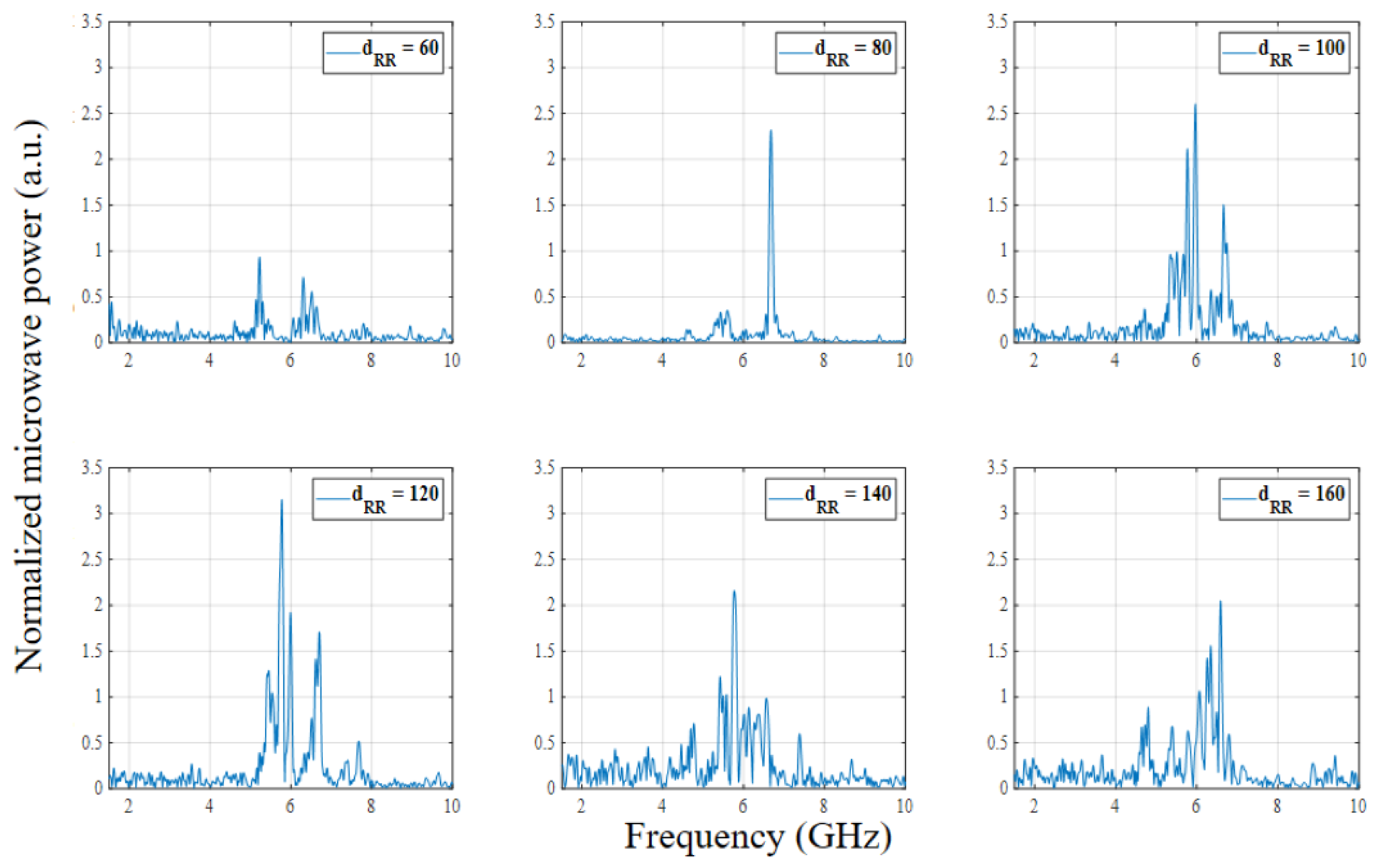
The influence of the diameter of the center hole in the ring reflector on the frequency of the generated microwave is analyzed through simulations. The FFT results for the microwave power from the axial vircator are depicted in Figure 6. The figure shows that the dominant frequencies are formed between 5.3 GHz and 6.5 GHz irregularly. According to the simulations, it seems that the diameter of the center hole in the ring reflector has no notable influence on the dominant frequency change. The simulations show that the frequency of the axial vircator tends to form in a slightly higher region when the diameter of the hole in the ring reflector is below 100 mm, and in a lower region when the diameter is above 100 mm.
3.2. Experimental Results
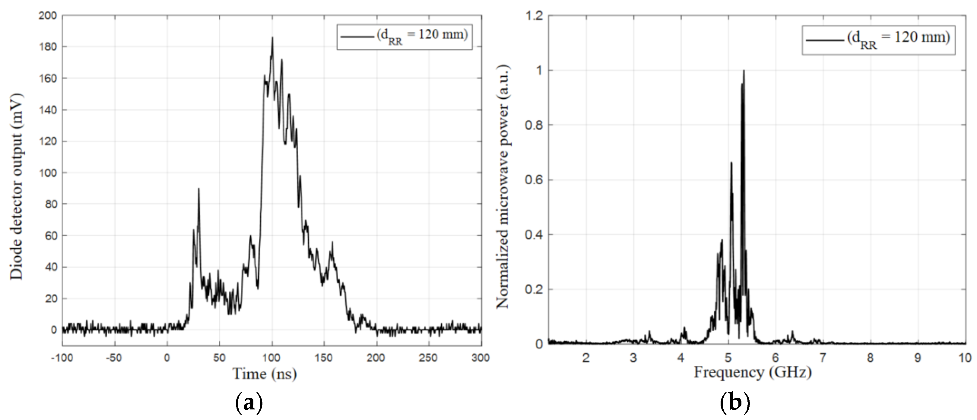
Although the diameter of the hole in the ring reflector was simulated in 2 mm steps, the experiments were conducted in 20 mm steps. The optimum diameter of the ring reflector to enhance the axial vircator output was investigated through the experiments. The axial vircator was driven using the 10-stage PFN-Marx generator. The voltage and current waveforms were measured using a capacitive voltage divider and a Pearson coil. The peak and plateau voltages were −196 ± 5 kV and −150 ± 7 kV. The rise time and pulse width of the voltage pulse were 25 ns and around 200 ns, respectively. The peak current was −5.6 ± 0.7 kA. The change in the diameter of the center hole in the ring reflector has no distinguishable influence on the vircator impedance or on the diode voltage and current. The microwave radiated from the axial vircator is measured using an RF diode detector. The voltage measured by the detector is converted to microwave power. The frequency spectrum of the radiated microwave is plotted through the FFT. The microwave power at the vircator window is calculated using Friis’s equation, as shown in Section 2.2, considering the gain of the transmitting and receiving antenna, and the attenuation at the RF measuring system. The dominant frequency obtained from the FFT is used in the calculation of the equation. The typical diode detector waveform and frequency spectrum waveform are shown in Figure 7. Figures are recorded when the axial vircator is driven by installing the ring reflector, of which the diameter of the center hole is 120 mm. Figure 7a shows that the microwave is generated for around 160 ns and has its peak in the middle of the pulse. The microwave is radiated for a period shorter than the voltage pulse width because its generation is considered to begin after the voltage pulse arrives at its plateau. Figure 7b shows the typical frequency spectrum of the axial vircator with the ring reflector when the diameter of the hole in the ring reflector is 120 mm. The figure shows that the dominant frequency when the hole diameter is 120 mm is formed at around 5.3 GHz. The overall experimental data are arranged in Table 3. The experimental results show that the average peak power from the axial vircator is the largest when the hole diameter in the ring reflector is 120 mm. The microwave powers are increased as the hole diameter increases to 120 mm, and decrease as the hole diameter increases further. The dominant frequency of the microwave from the axial vircator is formed between 5.3 GHz and 5.6 GHz. The experimental results show that the change in the dominant frequency depending on the hole diameter is indistinct whether it is caused due to the hole diameter or the environmental conditions.
The normalized microwave power depending on the diameter of the hole in the ring reflector is shown in Figure 8. Both the simulation results and the experimental results are depicted in the figure. A previous study showed that the average peak power from the axial vircator without the ring reflector was 11.22 MW. The results for the microwave power depicted in Figure 8 are normalized using the results on the axial vircator without the ring reflector. Although the tendencies are analogous, the detailed change and the amount of microwave enhancement in the experimental results because of the ring reflector differ from those of the simulations. The figure shows that the microwave power enhancement of both the simulations and experiments is largest when the diameter of the hole in the ring reflector is 120 mm. Although the microwave power is increased by about 200% in the simulations, the experiments show that the microwave power is increased by about 120%. When the diameter of the hole in the ring reflector is below 80 mm, the microwave enhancement is small compared to other diameters. The figure shows that the desired diameter of the hole in the ring reflector for its proper use is between 110 mm and 140 mm. Furthermore, the figure shows that the microwave power enhancement decreases drastically when the diameter of the hole in the ring reflector is changed from 140 mm to 160 mm. Figure 9 shows the simulation results, experimental results, and simulation trend of the dominant frequency versus the diameter of the hole in the ring reflector. The simulations show that the dominant frequency of the vircator is formed between 5.3 GHz and 6.8 GHz. The simulation trend plot shows that the dominant frequency of the microwave from the axial vircator increases when the diameter of the ring reflector increases from 60 mm to 80 mm. After it reaches 6.8 GHz, the dominant frequency decreases when the diameter increases to 140 mm. When the diameter is increased further, the microwave frequency increases again to around 6.5 GHz. The experimental plot on the dominant frequency shows similar tendencies to the simulation trend plot. Notable differences between the simulation results and the experimental results are the amount of variation, the frequency band, and the detailed inflection point of change. The experimental results show that the dominant frequencies are formed at a lower band compared to the simulations. These differences are considered to be caused by the error in the experimental system. Unlike the simulations, the AK gap distance cannot be exactly 6 mm.
4. Conclusions
In this paper, the power enhancement and the optimum diameter of the ring reflector hole for the axial vircator were investigated using PIC simulations and experiments. The operation features of the axial vircator with the ring reflector were studied and analyzed by varying its diameter in 2 mm steps in the simulations and 20 mm steps in the experiments. The experimental HPM system was driven using a 10-stage PFN-Marx generator by applying a high-voltage pulse of −150 kV. In the studies, the anode-to-cathode distance and anode-to-ring-reflector distance were fixed at 6 mm and 9 mm, respectively. Although the amount of power enhancement differs in the simulations and experiments, the power enhancement tendencies of the experiments were similar to those of the simulations. The simulations and experiments show that the microwave power from the axial vircator was barely enhanced when the hole diameter in the ring reflector was 60 mm. However, the microwave power from the vircator was drastically increased as the hole diameter of the ring reflector was increased to 120 mm. The experiments show that the peak microwave power of 23.67 MW was observed when the hole diameter of the ring reflector was 120 mm. The experiments and simulations show that a further increase in the hole diameter after 120 mm results in a reduction of the microwave power enhancement. The use of the ring reflector enhances the microwave power from the vircator by forming a cavity. The cavity region acts on the creation of the microwave feedback and microwave-electron interactions. The hole diameter of 120 mm was the optimum point when maximizing the cavity action of the ring reflector and minimizing the blocking structure of the microwave. The dominant frequency of the axial vircator was formed between 5.4 GHz and 6.6 GHz in the simulations. The simulations show that the dominant frequencies have sinusoidal-like tendencies depending on the hole diameter of the ring reflector. The experimental results show that the dominant frequency of the microwave from the vircator was formed between 5.3 GHz and 5.6 GHz. The frequency tendencies of the experimental results were similar to those of the simulations. However, the trend of the experimental plot was ambiguous regarding the estimation of whether it was matched with the simulation results.
Author Contributions
Conceptualization, W.-I.K., S.-H.K.; methodology, W.-I.K., S.-H.K.; software, W.-I.K.; validation, W.-I.K., S.-H.K.; formal analysis, W.-I.K.; investigation, W.-I.K., S.-H.K.; resources, W.-I.K.; data curation, W.-I.K.; writing—original draft preparation, W.-I.K.; writing—review and editing, K.-C.K. All authors have read and agreed to the published version of the manuscript.
Funding
This research received no external funding.
Conflicts of Interest
The authors declare no conflict of interest.
References
- Feng, J.; Li, X.; Hu, J.; Cai, J. General Vacuum Electronics. J. Electromagn. Eng. Sci. 2020, 20, 1–8. [Google Scholar] [CrossRef]
- Barker, R.J.; Schamiloglu, E. High-Power Microwave Sources and Technologies; Wiley-IEEE Press: Hoboken, NJ, USA, 2001. [Google Scholar]
- Benford, J.; Swegle, J.A.; Schamiloglu, E. High Power Microwaves, 3rd ed.; CRC Press: Boca Raton, FL, USA, 2015. [Google Scholar]
- Liu, Z.; Huang, H.; Jin, X.; Lei, L. Design of an X-Band Gigawatt Multibeam Relativistic Klystron Amplifier. IEEE Trans. Plasma Sci. 2014, 42, 3419–3422. [Google Scholar] [CrossRef]
- Jang, G.H.; Han, S.M.; Won, J.H.; Kim, J.H. HPM Technology Trend. JKIEES 2013, 24, 37–42. [Google Scholar]
- Schamiloglu, E. High Power Microwave Sources and Applications. IEEE MTT-S. 2004, 2, 1001–1004. [Google Scholar]
- Sedek, E.; Slomski, R. Overview of Microwave Direct Energy Weapons. In Proceedings of the 2015 Signal Processing Symposium (SPSympo), Debe, Poland, 10–12 June 2015; pp. 1–3. [Google Scholar]
- Giri, D.V.; Tesche, F.M. Classification of Intentional Electromagnetic Environments (IEME). IEEE Trans. Electromagn. Compat. 2004, 46, 322–328. [Google Scholar] [CrossRef]
- Farmer, W.A.; Cohen, B.I.; Eng, C.D. On the Validity of Certain Approximations Used in the Modeling of Nuclear EMP. IEEE Trans. Nucl. Sci. 2016, 63, 1259–1267. [Google Scholar] [CrossRef]
- Hao, R.; Zhang, X.; Gao, H.; Wu, H.; Cheng, J. A novel high-altitude electromagnetic pulse (HEMP) protection circuit for RF applications. Microelectron. Eng. 2019, 84, 1–8. [Google Scholar] [CrossRef]
- Kim, S.H.; Lee, C.J.; Kim, W.I.; Ko, K.C. Experimental Investigation into the Optimum Position of a Ring Reflector for an Axial Virtual Cathode Oscillator. Electronics 2021, 10, 1878. [Google Scholar] [CrossRef]
- Chen, Y.; Mankowski, J.; Walter, J.; Kristiansen, M. Cathode and Anode Optimization in a Virtual Cathode Oscillator. IEEE Trans. Dielectr. Electr. Insul. 2007, 14, 1037–1044. [Google Scholar] [CrossRef]
- Li, L.; Men, T.; Liu, L. Dynamics of virtual cathode oscillation analyzed by impedance changes in high-power diodes. Int. J. Appl. Phys. 2007, 102, 123309. [Google Scholar] [CrossRef]
- Walter, J.W.; Lynn, C.F.; Dickens, J.C.; Kristiansen, M. Operation of a Sealed-Tube-Vircator High-Power-Microwave Source. IEEE Trans. Plasma Sci. 2012, 40, 1618–1621. [Google Scholar] [CrossRef]
- Mumtaz, S.; Lim, J.S.; Ghimire, B. Enhancing the power of high power microwaves by using zone plate and investigations for the position of virtual cathode inside the drift tube. J. Plasma Phys. 2018, 25, 103113. [Google Scholar] [CrossRef]
- Parson, J.M.; Lynn, C.F.; Scott, M.C.; Calico, S.E.; Dickens, J.C.; Neuber, A.A.; Mankowski, J.J. A Frequency Stable Vacuum-Sealed Tube High-Power Microwave Vircator Operated at 500 Hz. IEEE Electron Device Lett. 2015, 36, 508–510. [Google Scholar] [CrossRef]
- Andersson, J.; Jansson, M.; Aberg, D. Frequency Dependence of the Anod-Cathode Gap Spacing in a Coaxial Vircator System. IEEE Trans. Plasma Sci. 2013, 41, 2758–2762. [Google Scholar] [CrossRef]
- Jiang, W. Time-Frequency Analysis of Virtual-Cathode Oscillator. IEEE Trans. Plasma Sci. 2010, 38, 1325–1328. [Google Scholar] [CrossRef]
- Cassany, B.; Desanlis, T.; Galtie, A.; Gardelle, J.; Modin, P.; Voisin, L. High current fast Marx generator and vircator experiments. In Proceedings of the Conference Record of the Twenty-Sixth International Power Modulator Symposium, 2004 and 2004 High-Voltage Workshop, San Francisco, CA, USA, 23–26 May 2004; pp. 441–444. [Google Scholar]
- Rainwater, K.; Darunett, D.; Lynn, C.; Dickens, J.; Neuber, A.; Mankowski, J. A 160 J, 100 Hz rep rate, compact Marx generator for driving and HPM source. In Proceedings of the 2016 IEEE International Power Modulator and High Voltage Conference (IPMHVC), San Francisco, CA, USA, 6–9 July 2016; pp. 228–230. [Google Scholar]
- Barnett, D.H.; Neuber, A.A.; Dickens, J.C.; John, J.; Mankowski, J. CST Particle-In-Cell Modeling of A Tunable Reflex-Triode Vircator. In Proceedings of the 2018 IEEE International Power Modulator and High Voltage Conference (IPMHVC), Jackson, WY, USA, 3–7 June 2018; pp. 133–135. [Google Scholar]
- Elfsberg, M.; Hurtig, T.; Larsson, A.; Moller, C.; Nyholm, E. Experimental Studies of Anode and Cathode Materials in a Repetitive Driven Axial Vircator. IEEE Trans. Plasma Sci. 2008, 36, 688–693. [Google Scholar] [CrossRef]
- Jeon, W.; Sung, K.Y.; Lim, J.E.; Song, K.B.; Seo, Y.; Choi, E.H. A Diode Design Study of the Virtual Cathode Oscillator with a Ring-Type Reflector. IEEE Trans. Plasma Sci. 2005, 33, 2011–2016. [Google Scholar] [CrossRef]
- Champeaux, S.; Gouard, P.; Cousin, R.; Larour, J. Improved Design of a Multistage Axial Vircator with Reflectors for Enhanced Performances. IEEE Trans. Plasma Sci. 2016, 44, 31–38. [Google Scholar] [CrossRef]
- Jeon, W.; Lim, J.E.; Moon, M.W.; Jung, K.B.; Park, W.B.; Shin, H.M.; Seo, Y.; Choi, E.H. Output characteristics of the high-power microwave generated from a coaxial vircator with a bar reflector in a drift region. IEEE Trans. Plasma Sci. 2006, 34, 937–944. [Google Scholar] [CrossRef]
- Champeaux, S.; Gouard, P.; Cousin, R.; Larour, J. Numerical evaluation of the role of reflectors to maximize the power efficiency of an axial Vircator. In Proceedings of the 2013 IEEE 14th International Vacuum Electronics Conference (IVEC), Paris, France, 21–23 May 2013; pp. 1–2. [Google Scholar]
- Moller, C.; Hurtig, T.; Larsson, A.; Nyholm, E. Numerical simulations of the influence of a reflector in a coaxial vircator. In Proceedings of the 2019 IEEE Pulsed Power Conference, Washington, DC, USA, 28 June–2 July 2009; pp. 529–532. [Google Scholar]
- Zhang, H.; Yang, J.; Lin, J.; Yang, X. A compact bipolar pulse-forming network-Marx generator based on pulse transformers. AIP 2013, 84, 114705. [Google Scholar] [CrossRef]
- Barnentt, D.H.; Rainwater, K.; Dickens, J.C.; Neuber, A.A.; Mankowski, J.J. A Reflex Triode System with Multicavity Adjustment. IEEE Trans. Plasma Sci. 2019, 47, 1472–1476. [Google Scholar] [CrossRef]
- Sullivan, D.J. High Power Microwave Generation from a Virtual Cathode Osillator (Vircator). IEEE Tans Nuclear Sci. 1983, 30, 3426–3428. [Google Scholar] [CrossRef]
- Adhikary, B.; Shyam, A.; Shukla, R.; Sharma, S.K. Fast Marx Generator for Directly Driving a Virtual Cathode Oscillator. J Korean Phys Soc. 2011, 59, 3476–3480. [Google Scholar] [CrossRef]
- Lassalle, F.; Morell, A.; Loyen, A.; Chanconie, T.; Roques, B.; Toury, M.; Vezinet, R. Development and Test of a 400-kV PFN Marx with Compactness and Rise Time Optimization. IEEE Trans. Plasma Sci. 2018, 46, 3313–3319. [Google Scholar] [CrossRef]
Figure 1.
Schematic diagram of the experimental system.

Figure 2.
Picture of the six-stage PFN.

Figure 3.
Picture of the 10-stage PFN-Marx generator.

Figure 4.
Inner structure of the axial vircator.

Figure 5.
Normalized microwave power of the axial vircator with and without the ring reflector.

Figure 6.
Frequency spectrum of the axial vircator with and without the ring reflector.

Figure 7.
Typical waveform of the axial vircator when dRR = 120 mm: (a) diode detector and (b) frequency spectrum.
Figure 7.
Typical waveform of the axial vircator when dRR = 120 mm: (a) diode detector and (b) frequency spectrum.

Figure 8.
Normalized microwave power of the simulations and experiments as a function of the anode-to-ring-reflector distance.
Figure 8.
Normalized microwave power of the simulations and experiments as a function of the anode-to-ring-reflector distance.

Figure 9.
Dominant frequency of the simulations and experiments as a function of the anode-to-ring-reflector distance.
Figure 9.
Dominant frequency of the simulations and experiments as a function of the anode-to-ring-reflector distance.


Table 1.
Design parameters of the 10-stage PFN-Marx generator.
| Parameter | Value | Parameter | Value |
|---|---|---|---|
| Capacitance | 4.17 nF | Inductance | 37.5 nH |
| PFN stage | 6 | Marx stage | 10 |
| Charging voltage | −30 kV | Erected voltage | −300 kV |
| Pulse width | 150 ns | Characteristic impedance | 30 Ω |
Table 2.
Design parameters of the 10-stage PFN-Marx generator.
| Quantity | Value | Quantity | Value |
|---|---|---|---|
| Diameter | 200 mm | Electron emitting electric field | 100 kV/m |
| Length | 300 mm | Transparency of the mesh anode | 70% |
| Cathode surface | 200 mm | Pulse width | 25 ns |
| Anode surface | 26 mm | Flat top voltage | 150 kV |
Table 3.
Experimental results on the optimum diameter of the hole in the ring reflector.
| dRR | Pmin (MW) | Pmax (MW) | Pavg (MW) | Frequency (GHz) |
|---|---|---|---|---|
| Basic axial | 8.7 | 12.3 | 11.22 | 5.54 |
| 60 mm | 6.09 | 14.93 | 12.53 | 5.37 |
| 80 mm | 12.21 | 17.37 | 15.77 | 5.83 |
| 100 mm | 12.93 | 22.68 | 18.61 | 5.48 |
| 120 mm | 15.7 | 27.03 | 23.67 | 5.32 |
| 140 mm | 19.36 | 24.43 | 21.53 | 5.59 |
| 160 mm | 15.44 | 21.3 | 17.21 | 5.61 |
Publisher’s Note: MDPI stays neutral with regard to jurisdictional claims in published maps and institutional affiliations. |
© 2022 by the authors. Licensee MDPI, Basel, Switzerland. This article is an open access article distributed under the terms and conditions of the Creative Commons Attribution (CC BY) license (https://creativecommons.org/licenses/by/4.0/).
Share and Cite
MDPI and ACS Style
Kim, W.-I.; Kim, S.-H.; Ko, K.-C. Investigation of the Optimum Diameter of the Ring Reflector for an Axial Virtual Cathode Oscillator. Electronics 2022, 11, 2002. https://0-doi-org.brum.beds.ac.uk/10.3390/electronics11132002
AMA Style
Kim W-I, Kim S-H, Ko K-C. Investigation of the Optimum Diameter of the Ring Reflector for an Axial Virtual Cathode Oscillator. Electronics. 2022; 11(13):2002. https://0-doi-org.brum.beds.ac.uk/10.3390/electronics11132002
Chicago/Turabian StyleKim, Wan-Il, Se-Hoon Kim, and Kwang-Cheol Ko. 2022. "Investigation of the Optimum Diameter of the Ring Reflector for an Axial Virtual Cathode Oscillator" Electronics 11, no. 13: 2002. https://0-doi-org.brum.beds.ac.uk/10.3390/electronics11132002
Note that from the first issue of 2016, this journal uses article numbers instead of page numbers. See further details here.