
Design and Analysis Considering Magnet Usage of Permanent Magnet Synchronous Generator Using Analytical Method

 , , ,
, , ,
Abstract
:1. Introduction
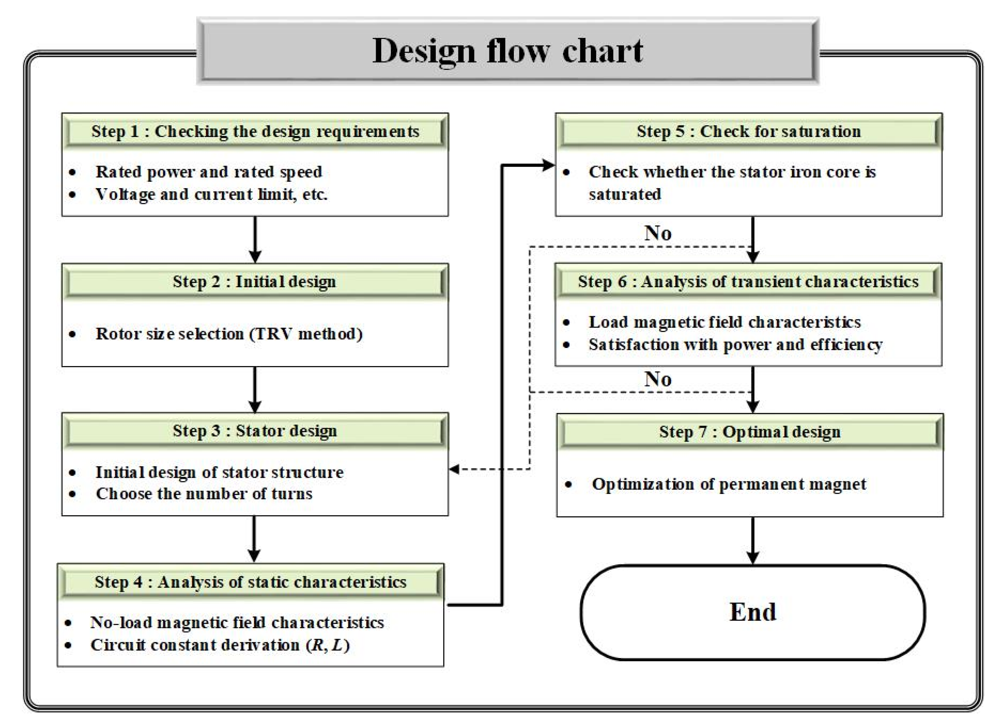
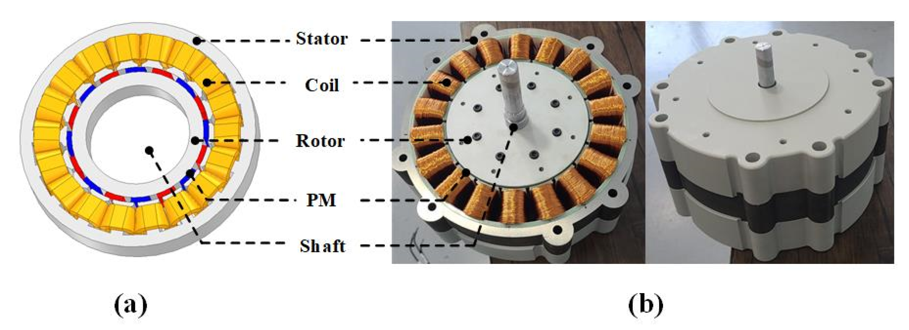
2. Initial Design
2.1. Process of Initial Design
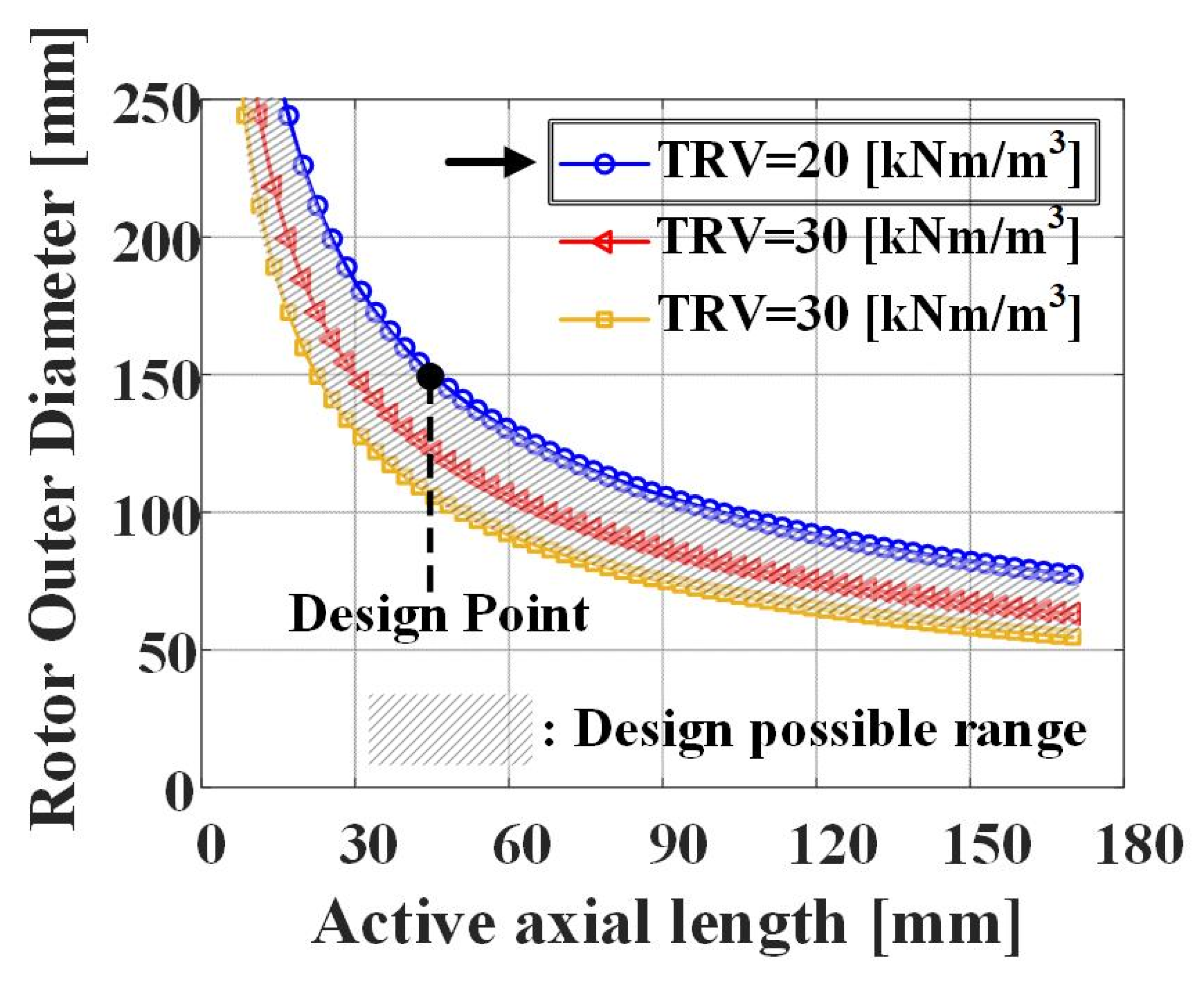
2.2. Size Selection
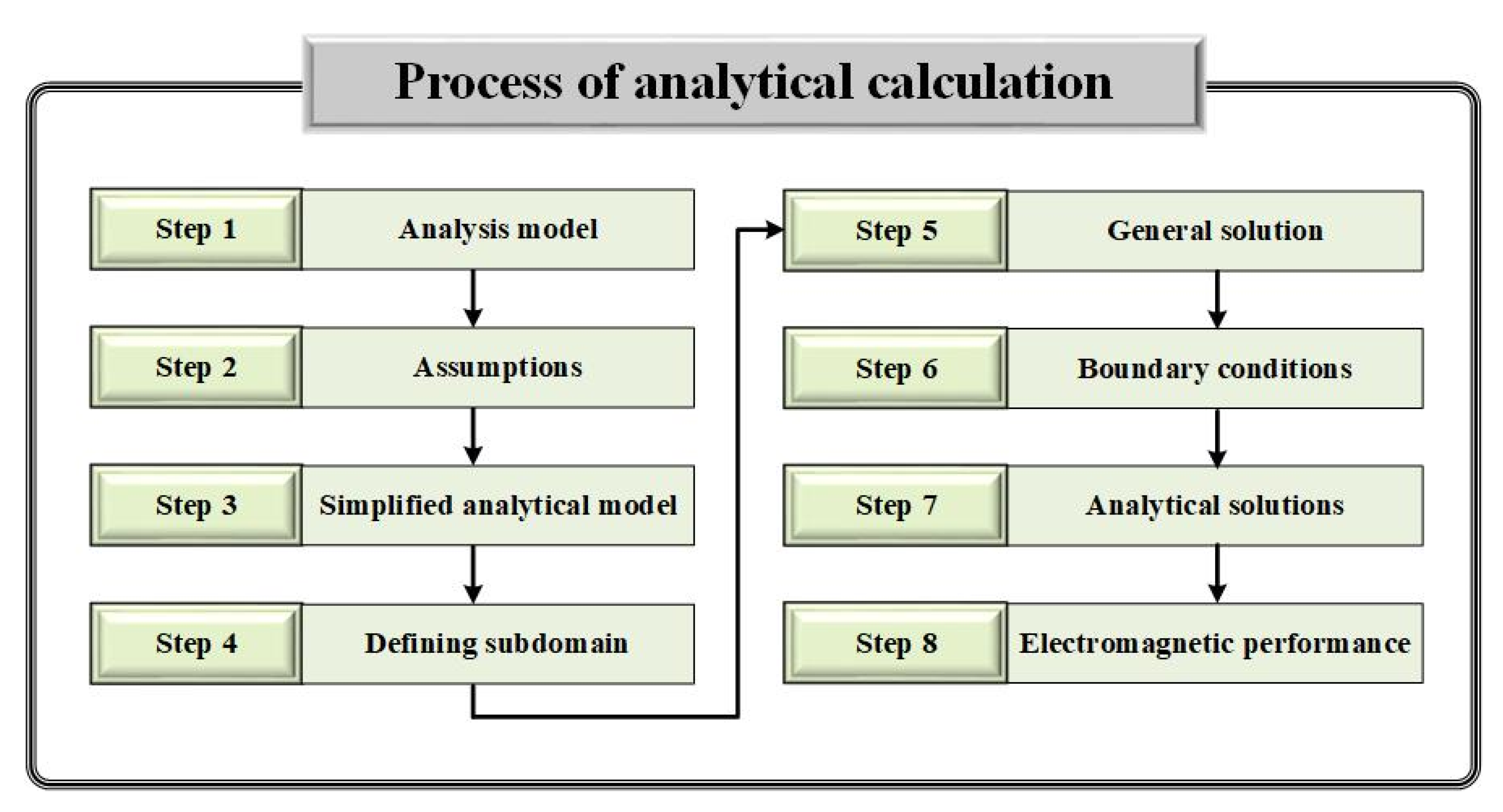
3. Magnetic Field Characteristics Analysis Using Analytical Methods
3.1. Analytical Method
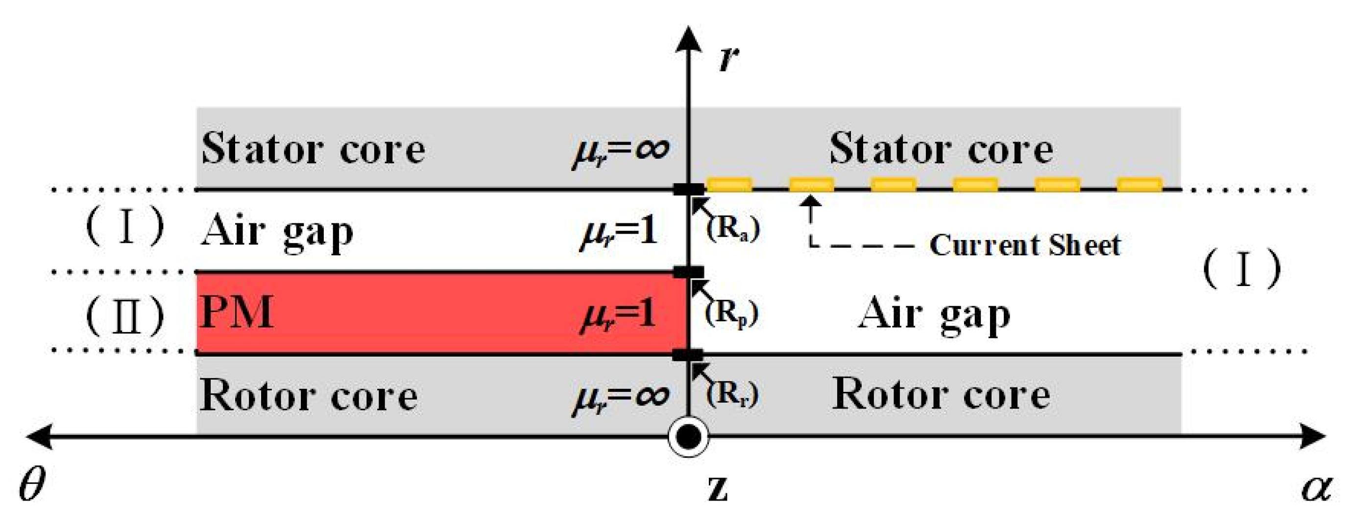
3.2. Assumptions for Analysis
3.3. Magnetization Modeling and Current Modeling
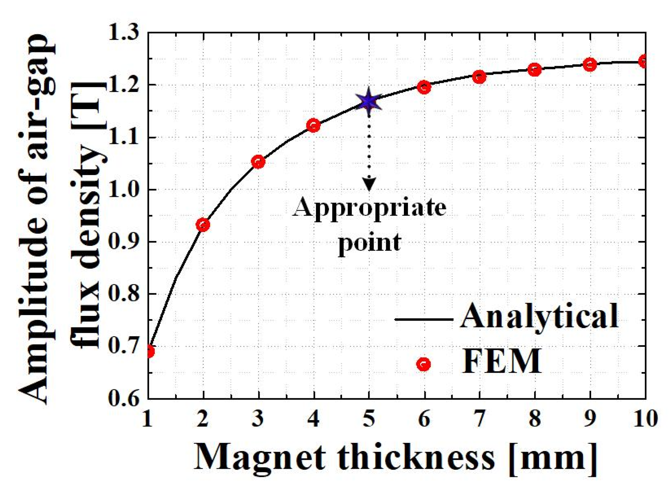
3.4. Selection of Appropriate Magnet Usage Point
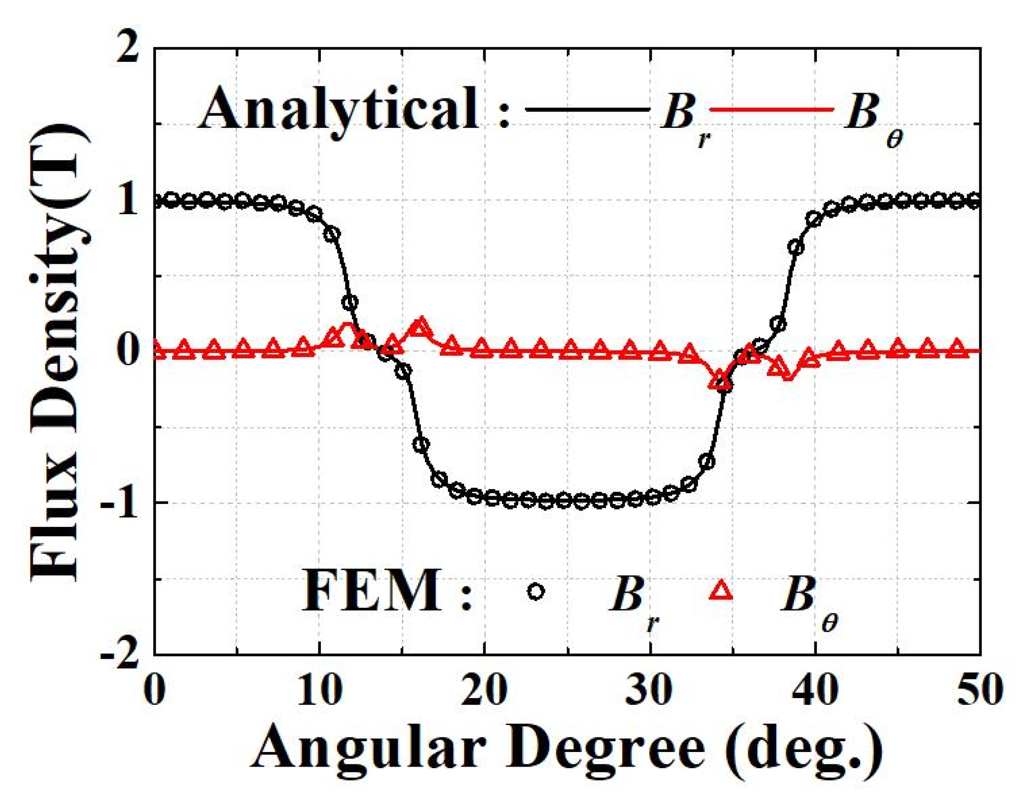
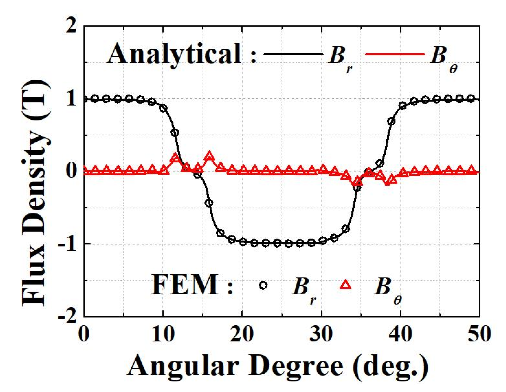
3.5. Open Circuit Magnetic Field Characteristics
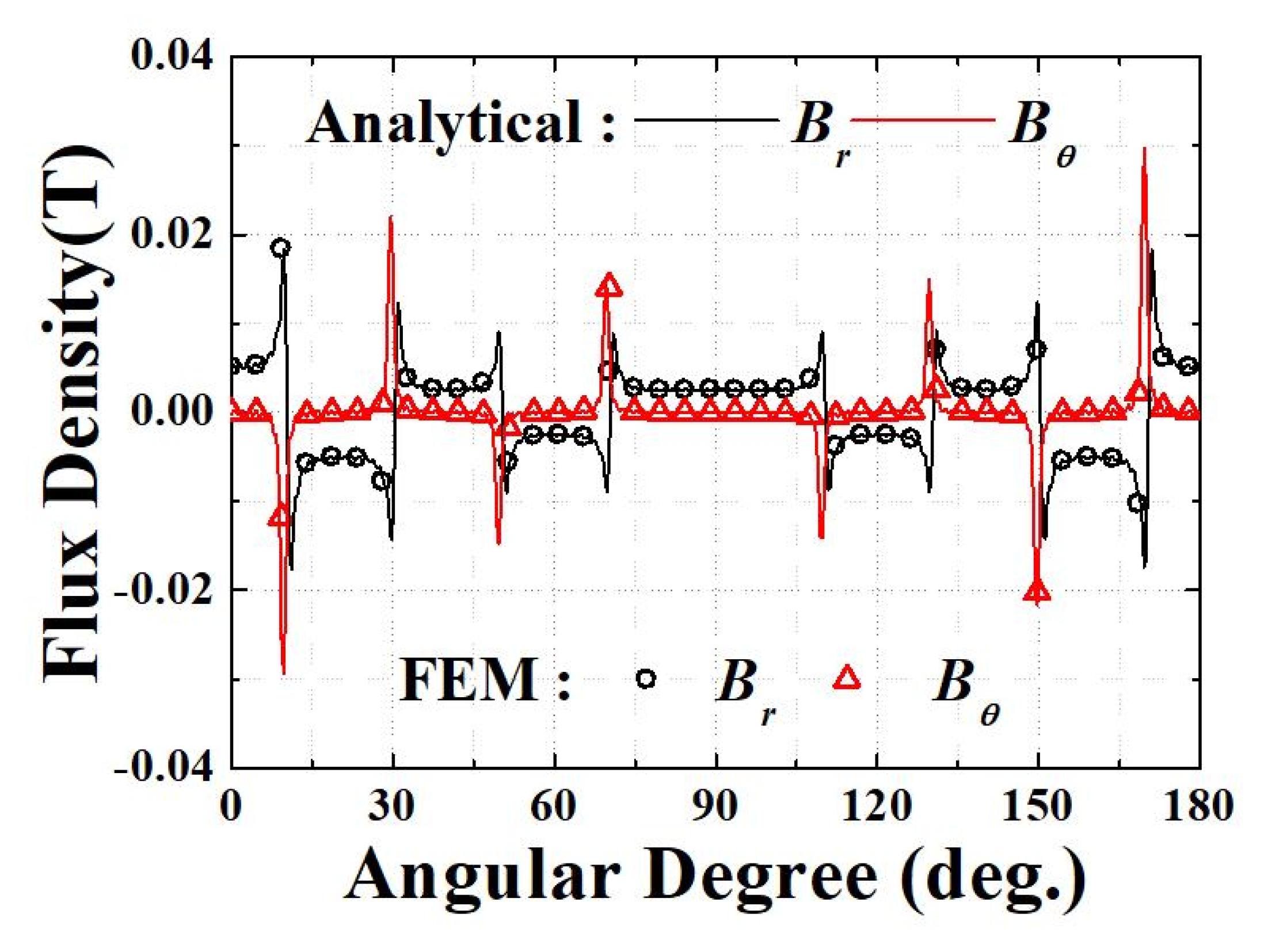
3.6. Magnetic Field Characteristics of Armature Reaction
4. Equivalent Circuit Method (ECM)
4.1. Circuit Constant Derivation
4.1.1. Phase Resistance
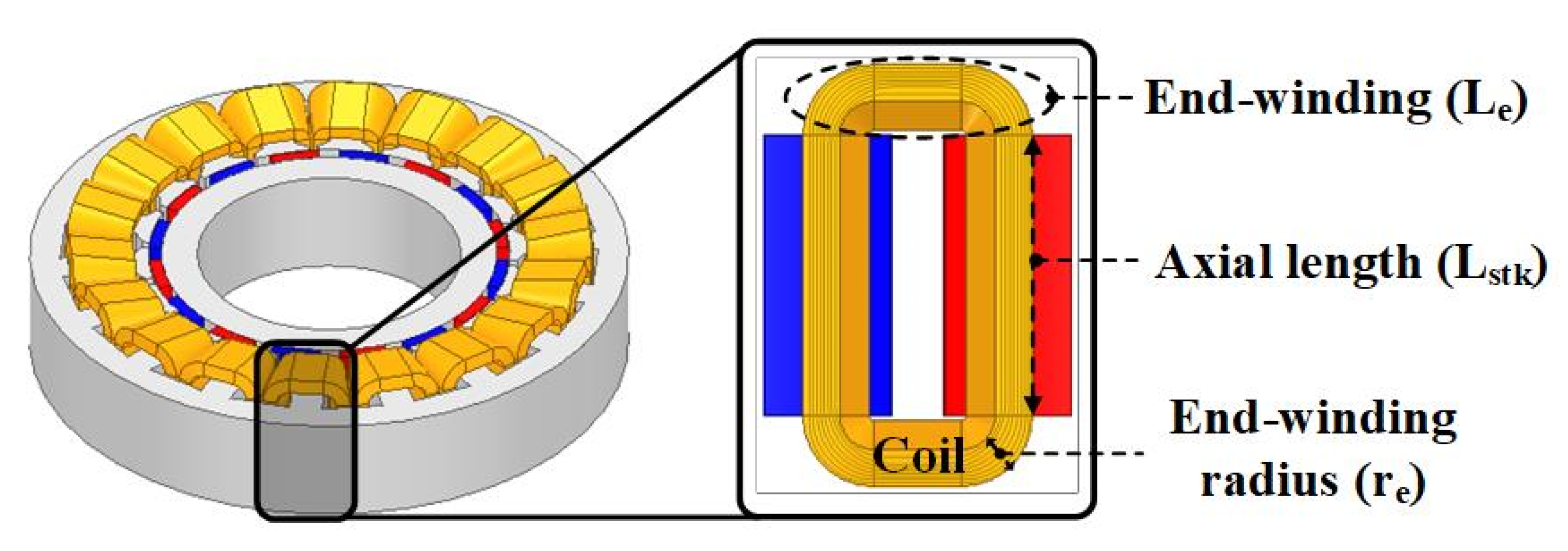
4.1.2. Inductance
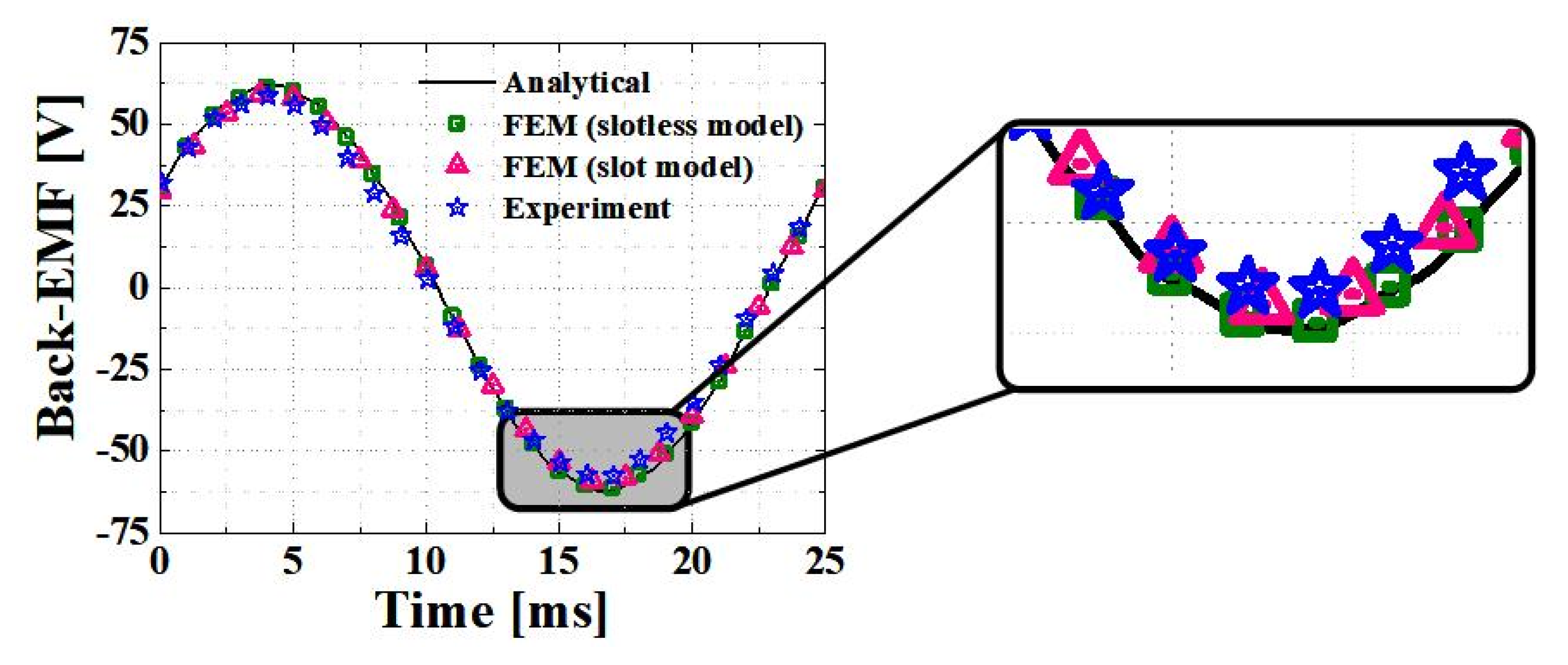
4.1.3. Back EMF
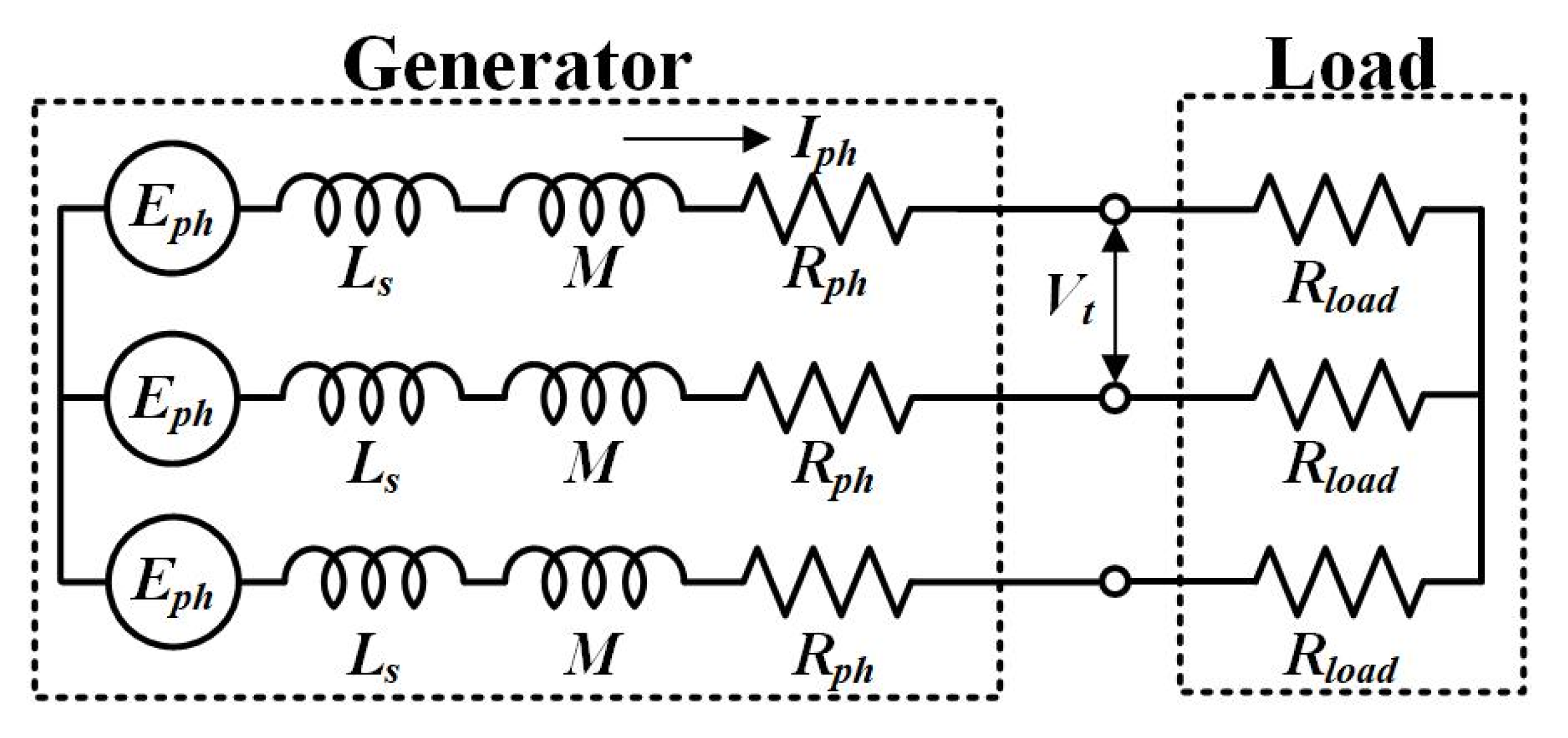
4.2. Composition of Equivalent Circuit
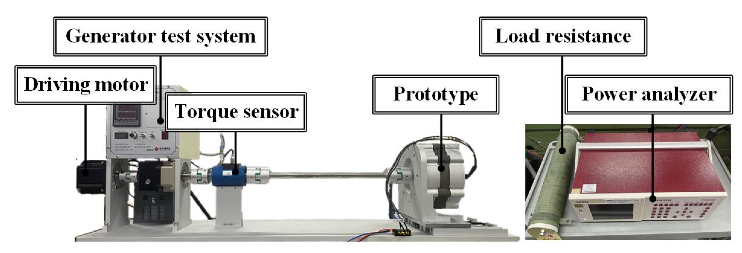
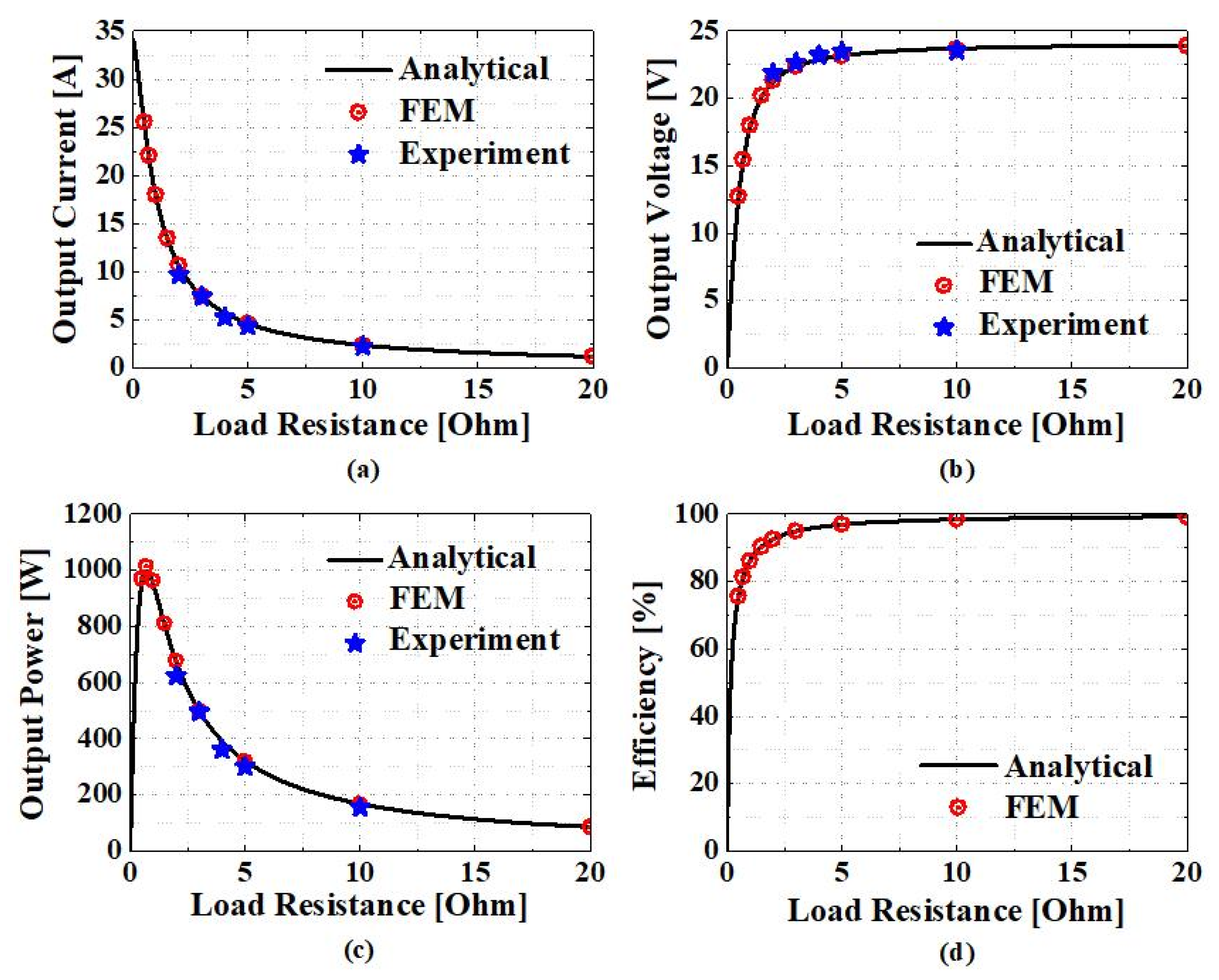
4.3. Comparison of Generating Characteristics Analysis Results
5. Conclusions
Author Contributions
Funding
Institutional Review Board Statement
Informed Consent Statement
Data Availability Statement
Conflicts of Interest
References
- He, C.; Wu, T. Analysis and design of surface permanent magnet synchronous motor and generator. CES Trans. Electr. Mach. Syst. 2019, 3, 94–100. [Google Scholar] [CrossRef]
- Kumar, R.R.; Devi, P.; Chetri, C.; Vardhan, A.S.S.; Elavarasan, R.M.; Mihet-Popa, L.; Saket, R.K. Design and Characteristics Investigation of Novel Dual Stator Pseudo-Pole Five-Phase Permanent Magnet Synchronous Generator for Wind Power Application. IEEE Access 2020, 8, 175788–175804. [Google Scholar] [CrossRef]
- Song, Z.; Liu, C.; Feng, K.; Zhao, H.; Yu, J. Field Prediction and Validation of a Slotless Segmented-Halbach Permanent Magnet Synchronous Machine for More Electric Aircraft. IEEE Trans. Transp. Electrif. 2020, 6, 1577–1591. [Google Scholar] [CrossRef]
- Shin, K.; Kim, K.; Hong, K.; Choi, J. Detent Force Minimization of Permanent Magnet Linear Synchronous Machines Using Subdomain Analytical Method Considering Auxiliary Teeth Configuration. IEEE Trans. Magn. 2017, 53, 8104504. [Google Scholar] [CrossRef]
- Hu, H.; Zhao, J.; Liu, X.; Guo, Y. Magnetic Field and Force Calculation in Linear Permanent-Magnet Synchronous Machines Accounting for Longitudinal End Effect. IEEE Trans. Ind. Electron. 2016, 63, 7632–7643. [Google Scholar] [CrossRef] [Green Version]
- Shin, K.; Cho, H.; Lee, S.; Choi, J. Armature Reaction Field and Inductance Calculations for a Permanent Magnet Linear Synchronous Machine Based on Subdomain Model. IEEE Trans. Magn. 2017, 53, 8105804. [Google Scholar] [CrossRef]
- Ullah, W.; Khan, F.; Sulaiman, E.; Sami, I.; Ro, J.-S. Analytical Sub-Domain Model for Magnetic Field Computation in Segmented Permanent Magnet Switched Flux Consequent Pole Machine. IEEE Access 2021, 9, 3774–3783. [Google Scholar] [CrossRef]
- Sung, S.; Jeong, J.; Park, Y.; Choi, J.; Jang, S. Improved Analytical Modeling of Axial Flux Machine With a Double-Sided Permanent Magnet Rotor and Slotless Stator Based on an Analytical Method. IEEE Trans. Magn. 2012, 48, 2945–2948. [Google Scholar] [CrossRef]
- Jang, G.; Kim, C.; Seo, S.; Shin, K.; Yoon, I.; Choi, J. Torque Characteristic Analysis and Measurement of Magnetic Rack–Pinion Gear Based on Analytical Method. IEEE Trans. Magn. 2019, 55, 1–5. [Google Scholar] [CrossRef]
- Jang, S.-M.; Choi, J.-Y.; Jeong, S.-S. Electromagnetic analysis and control parameter estimation of moving-coil linear oscillatory actuator. J. Appl. Phys. 2006, 99, 08R307. [Google Scholar] [CrossRef]
- Yeo, H.; Lim, D.; Jung, H. Magnetic Equivalent Circuit Model Considering the Overhang Structure of an Interior Permanent-Magnet Machine. IEEE Trans. Magn. 2019, 55, 1–4. [Google Scholar] [CrossRef]
- Forstner, G.; Kugi, A.; Kemmetmüller, W. A Magnetic Equivalent Circuit Based Modeling Framework for Electric Motors Applied to a PMSM with Winding Short Circuit. IEEE Trans. Power Electron. 2020, 35, 12285–12295. [Google Scholar] [CrossRef]
- Caruso, M.; di Tommaso, A.O.; Emma, S.; Miceli, R. Analysis, characterization and minimization of IPMSMs cogging torque with different rotor structures. In Proceedings of the 2015 Tenth International Conference on Ecological Vehicles and Renewable Energies (EVER), Monte-Carlo, Monaco, 31 March–2 April 2015; pp. 1–6. [Google Scholar]
- Gul, W.; Gao, Q.; Lenwari, W. Optimal Design of a 5-MW Double-Stator Single-Rotor PMSG for Offshore Direct Drive Wind Turbines. IEEE Trans. Ind. Appl. 2020, 56, 216–225. [Google Scholar] [CrossRef]
- Barmpatza, A.C.; Kappatou, J.C. Finite Element Method Investigation and Loss Estimation of a Permanent Magnet Synchronous Generator Feeding a Non-Linear Load. Energies 2018, 11, 3404. [Google Scholar] [CrossRef] [Green Version]
- Zhao, W.; Xing, F.; Wang, X.; Lipo, T.A.; Kwon, B. Design and Analysis of a Novel PM-Assisted Synchronous Reluctance Machine With Axially Integrated Magnets by the Finite-Element Method. IEEE Trans. Magn. 2017, 53, 1–4. [Google Scholar] [CrossRef]
- Kumar, R.R.; Singh, S.K.; Srivastava, R.K.; Vardhan, A.S.S.; Elavarasan, R.M.; Saket, R.K.; Hossain, E. Modeling of Airgap Fluxes and Performance Analysis of Five Phase Permanent Magnet Synchronous Generator for Wind Power Application. IEEE Access 2020, 8, 195472–195486. [Google Scholar] [CrossRef]
- Du, X.; Liu, G.; Chen, Q.; Xu, G.; Xu, M.; Fan, X. Optimal Design of an Inset PM Motor With Assisted Barriers and Magnet Shifting for Improvement of Torque Characteristics. IEEE Trans. Magn. 2017, 53, 1–4. [Google Scholar] [CrossRef]
- Artal-Sevil, J.S.; Dufo, R.; Domínguez, J.A.; Bernal-Agustín, J.L. Small wind turbines in smart grids. Transformation of electrical machines in permanent magnet synchronous generators. In Proceedings of the 2018 Thirteenth International Conference on Ecological Vehicles and Renewable Energies (EVER), Monte-Carlo, Monaco, 10–12 April 2018; pp. 1–8. [Google Scholar]
- Eklund, P.; Sjölund, J.; Berg, M.; Leijon, M.; Eriksson, S. Experimental Evaluation of a Rare Earth-Free Permanent Magnet Generator. IEEE Trans. Energy Convers. 2021, 36, 3–10. [Google Scholar] [CrossRef]
- Wu, L.; Yin, H.; Wang, D.; Fang, Y. On-Load Field Prediction in SPM Machines by a Subdomain and Magnetic Circuit Hybrid Model. IEEE Trans. Ind. Electron. 2020, 67, 7190–7201. [Google Scholar] [CrossRef]
- Dai, T.; Li, H.; Li, J.; Yuan, B.; Liu, X. A Hybrid Calculation Method of Radial Electromagnetic Force Based on Finite Element Method and Analytic Method in A Permanent Magnet Synchronous Machine. In Proceedings of the 2019 22nd International Conference on Electrical Machines and Systems (ICEMS), Harbin, China, 11–14 August 2019; pp. 1–4. [Google Scholar]
- Liu, X.; Hu, H.; Zhao, J.; Belahcen, A.; Tang, L.; Yang, L. Analytical Solution of the Magnetic Field and EMF Calculation in Ironless BLDC Motor. IEEE Trans. Magn. 2016, 52, 1–10. [Google Scholar] [CrossRef]
- Koo, M.; Choi, J.; Jeong, J.; Shin, H.; Hong, K. Characteristic Analysis of Permanent-Magnet Synchronous Generator With Slotless Stator Structure Considering Magnetic/Mechanical Air Gap Using Semi-3-D Analytical Method. IEEE Trans. Magn. 2015, 51, 1–4. [Google Scholar]
- Hendershot, J.R.; Miller, T.J.E. Design of Brushless Permanent Magnet Machines; Motor Design Books LLC: Venice, FL, USA, 2010. [Google Scholar]
- Choi, G.; Jahns, T.M. Reduction of Eddy-Current Losses in Fractional-Slot Concentrated-Winding Synchronous PM Machines. IEEE Trans. Magn. 2016, 52, 8105904. [Google Scholar] [CrossRef]
- Ahsanullah, K.; Dutta, R.; Rahman, M.F. Analysis of Low-Speed IPMMs with Distributed and Fractional Slot Concentrated Windings for Wind Energy Applications. IEEE Trans. Magn. 2017, 53, 1–10. [Google Scholar] [CrossRef]
- Du, Z.S.; Lipo, T.A. Cost-Effective High Torque Density Bi-Magnet Machines Utilizing Rare Earth and Ferrite Permanent Magnets. IEEE Trans. Energy Convers. 2020, 35, 1577–1584. [Google Scholar] [CrossRef]
- Kim, K.; Park, H.; Jang, S.; You, D.; Choi, J. Comparative Study of Electromagnetic Performance of High-Speed Synchronous Motors With Rare-Earth and Ferrite Permanent Magnets. IEEE Trans. Magn. 2016, 52, 8203404. [Google Scholar] [CrossRef]
- Li, J.; Wang, K. Analytical Determination of Optimal PM-Arc Ratio of Consequent-Pole Permanent Magnet Machines. IEEE/ASME Trans. Mechatron. 2018, 23, 2168–2177. [Google Scholar] [CrossRef]


| Parameter | Value | Unit |
|---|---|---|
| Rated power | 500 | W |
| Rated speed | 300 | rpm |
| Permanent magnet | N35SH | - |
| Efficiency | 90 | % |
| Residual magnetic flux density | 1.21 | T |
| Current density limit | 7 | A/mm2 |
| Parameter | Designation | Unit |
|---|---|---|
| Ra | Inner radius of stator | mm |
| Rp | Outer radius of PMs | mm |
| Rr | Inner radius of PMs | mm |
| αp | Pole-arc ratio | - |
| so | Width of slot opening | mm |
| lstk | Axial length | mm |
| Open Circuit | Armature Reaction | ||
|---|---|---|---|
| Parameter | Value | Unit |
|---|---|---|
| Pole/slot | 16/18 | - |
| Stator diameter | 250 | mm |
| Rotor diameter | 150 | mm |
| Axial length | 45 | mm |
| Magnet thickness | 5 | mm |
| Winding | Concentrated | - |
| Pole-arc ratio | 0.82 | - |
| Air gap length | 1 | mm |
| Coil diameter | 0.511 | mm |
| Number of strands | 17 | - |
| Number of turns | 25 | - |
| Analytical | FEM | Experiment | |
|---|---|---|---|
| Phase resistance | 0.16 | 0.16 | 0.16 |
| Back EMF constant | 1.38 | 1.33 | 1.32 |
Publisher’s Note: MDPI stays neutral with regard to jurisdictional claims in published maps and institutional affiliations. |
© 2022 by the authors. Licensee MDPI, Basel, Switzerland. This article is an open access article distributed under the terms and conditions of the Creative Commons Attribution (CC BY) license (https://creativecommons.org/licenses/by/4.0/).
Share and Cite
Lee, J.-H.; Lee, H.-K.; Lee, Y.-G.; Lee, J.-I.; Jo, S.-T.; Kim, K.-H.; Park, J.-Y.; Choi, J.-Y. Design and Analysis Considering Magnet Usage of Permanent Magnet Synchronous Generator Using Analytical Method. Electronics 2022, 11, 205. https://0-doi-org.brum.beds.ac.uk/10.3390/electronics11020205
Lee J-H, Lee H-K, Lee Y-G, Lee J-I, Jo S-T, Kim K-H, Park J-Y, Choi J-Y. Design and Analysis Considering Magnet Usage of Permanent Magnet Synchronous Generator Using Analytical Method. Electronics. 2022; 11(2):205. https://0-doi-org.brum.beds.ac.uk/10.3390/electronics11020205
Chicago/Turabian StyleLee, Ji-Hun, Hoon-Ki Lee, Young-Geun Lee, Jeong-In Lee, Seong-Tae Jo, Kyong-Hwan Kim, Ji-Yong Park, and Jang-Young Choi. 2022. "Design and Analysis Considering Magnet Usage of Permanent Magnet Synchronous Generator Using Analytical Method" Electronics 11, no. 2: 205. https://0-doi-org.brum.beds.ac.uk/10.3390/electronics11020205