1. Introduction
In the course of the last decade, real-time simulators (RTS) have been under the focus of important research in almost all areas of electrical engineering. On the one hand, they can be used in the context of hardware-in-the-loop (HIL) testing, being the intermediate between offline simulations and real experimentations [
1,
2,
3,
4,
5,
6]. On the other hand, recent application trends consist in deploying these RTS as digital twins that are embedded (embedded RTS—eRTS) within the control system to provide additional functionalities, such as estimations/observations, online diagnostics and health monitoring, or also to be used in fault-tolerant and sensorless control [
7,
8,
9,
10].
Based on these assets, a digital twin can be advantageously used in the area of power electronics and more specifically in the context of HVDC grids that integrate modular multilevel converters (MMC) [
11,
12,
13,
14,
15,
16,
17,
18]. Indeed, bearing in mind the industrial demands in terms of reliability, the potential interest of an eRTS is to contribute in predicting, detecting, and compensating any faults that may appear around the power converter.
Following this line, several fault-tolerant strategies have been proposed in the literature [
17]. These studies mainly consider power switches faults that lead to cell failures, thus, needing to bypass the cell. Redundancy with hot-reserved cells, cold-reserved cells or operation with an asymmetrical SM count were analyzed in [
18]. However, other types of failures, such as communication or measurement failures, have not been considered.
In the proposed work, these measurement failures are addressed through the application of an eRTS in the context of voltage–sensorless control of a dc–dc MMC converter. The faulty situation that is specifically targeted is the loss of one or several submodule (SM) capacitor voltages due to a failure of their corresponding sensors. Indeed, these voltages are used in the controller, and in the case of fault, the system switches from the measured quantities to those estimated by the eRTS, avoiding further damages to the MMC hardware. Furthermore, in case of an important failure of the measurement system, the MMC can be shut down safely. Additionally, if the MMC is used in HVDC grids, the proposed system can avoid a sudden disconnection of the MMC, thus avoiding an abrupt interruption of the power flow.
However, to achieve such reliability tasks, the main concern when implementing the eRTS is how to obtain the right balance between (i) the complexity of the choice mathematical model, (ii) the need of optimizing the digital realization by choosing a performant digital solver and ensuring very short simulation time steps, and (iii) the selection of the digital platform that ensures fast execution times as well as high integration capacity [
9,
10,
11,
12].
Now when focusing on the proposed application, the MMC eRTS imposes an important challenge due to its inherent structure, which contains a large number of power switch submodules. Hence, computing its model equations implies a large number of mathematical operations, parallel executions, and above all, a very short time step. This is the reason why additional efforts have to be conducted when selecting the appropriate eRTS modularity and granularity. In this work, to ensure a high execution rate, each submodule of the MMC is individually represented by a dedicated model, leading to a full parallel structure.
This algorithmic organization implies the use of a fast and a highly integrated digital device, where the overall sensorless controller is to be implemented. In the proposed work, the chosen solution is based on a SoC-FPGA device (system-on-chip field-programmable gate array). The latter integrates in the same device a processing system (PS) along with FPGA programmable logic (PL) resources and many other analog, memory and interfacing peripherals [
19,
20,
21]. This set of features combined in a single chip makes these devices very suitable for implementing the sensorless controller, and all the tasks can be divided between PS and the PL sides, depending on their timing sensitivity [
22,
23,
24]. Then, with the used Xilinx Zynq-7020 device, the controller is implemented in the processing side using the hardwired ARM Cortex-A9 processor. As for the time-sensitive blocks (PWM, eRTS and measurements filtering), a full hardware implementation is privileged, using the FPGA fabric, and regarding the eRTS, it is firstly coded in C/C++ and implemented in hardware using the high-level synthesis (HLS) tools [
25,
26,
27].
The paper is organized as follows. In
Section 2, the adopted double-Π MMC topology and its associated controller are discussed. In
Section 3, the developed eRTS and its estimation principle are presented.
Section 4 is devoted to the hardware/software co-design description. Finally, in
Section 5, the performance results of the developed eRTS in the context of voltage–sensorless control are outlined, and all the obtained estimations are compared with their measured counterparts and validated in faulty operating conditions. Conclusions, nomenclature and references are provided at the end of this paper.
2. Description of the MMC Topology and Its Control
Several MMC topologies, including ac–ac, dc–dc and ac–dc converters have been developed since it was first proposed in 2003. In this paper, the dc–dc converter topology shown in
Figure 1 is considered for the implementation of the eRTS [
28]. The converter has two halves, one for each pole, and each half consists of two branches made up of N cascaded half-bridge (HB) or full-bridge (FB) submodules (SMs). The use of HB or FB–SMs depends on the voltage transformation ratio and the inner converter ac voltage.
The converter works as a dc–dc transformer that steps up or down the input dc voltage (Vdci) to the output dc voltage (Vdco). The series branches insert the dc voltage drop between the input and output sides and the derivation branches force the current difference between the input and the output (Idci–Idco) to flow through them. The shunt branches, which consist of an LC filter tuned at the circulating current frequency, recirculate the circulating ac current needed for the branch energy control.
At the beginning, the series and derivation branches should only generate a dc voltage and force the dc current to flow through them to transfer power between the input and output. However, this would cause energy drifts in the energy stored in these branches, that is, sustained charge/discharge of the SM capacitors. Given that these energy drifts in the series and derivation branches are opposite, ac voltages and ac currents can be used in each branch to exchange energy between them (
Figure 2). In this way, the energy drift caused by the dc current is balanced with the power exchange carried out by the ac current.
The developed MMC control strategy is directly inspired from Ref. [
28]. As shown in
Figure 3, the controller can be divided into three parts: (i) the branch energy control (
Figure 3a), (ii) the branch current control, see
Figure 3b and (iii) the capacitor balancing control, see
Figure 3c. Given that both converter halves operate in a similar manner, only the upper part is analyzed hereinafter.
2.1. Branch Energy Control
This part controls the average energy inside the series (
se) and derivation (
de) branches generating the appropriate references for the amplitude of the ac circulating current (
) and for the dc component of the derivation branch current (
), according to the following mathematical formulations
Considering that the power flows from the input to the output side of the converter, the term is the power injected in the series branch, whereas is the power extracted by the ac current. In steady state, both terms have to be the same in order to keep the branch energy constant. Similarly, is the power extracted from the derivation branch (note that when and vice versa) and is the power injected in the derivation branch. Again, in steady state, both terms have to be the same. Note that the power extracted from the series branch is the same as the power injected in the derivation branch.
The circulating
iq current (see
Figure 2), which is used for the SM capacitor voltage balancing within each branch, is regulated to be out of phase (π/2) with the
vu voltage. Thus, it does not contribute to the energy transfer between the series and derivation branches, and it is not considered in the previous analysis. Adding and rearranging Equation (1a,b) yields the following total power
In Equation (1a),
Ise depends on the output load (
Idco) so it is considered a disturbance that can be compensated in the loop (
Figure 3a). Thus, the series energy is controlled by setting the amplitude (
Iu) of the circulating current. Note that the amplitude of the branch ac voltage (
Vu) is kept constant. On the other hand, according to Equation (2), the total energy of each converter half can be regulated by means of the dc current flowing through the derivation branch (
Ide).
2.2. Branch Current Control
According to
Figure 2, the branch currents, which consist of dc and ac components, are as follows
The second part of the developed MMC controller is then dedicated to the PI-resonant control of the
ide current, which generates the
reference voltage for each submodule before the capacitor voltage balancing control, as illustrated in
Figure 3b. The
and
references are provided by the energy control part. The
current, which is used in the capacitor balancing control, is kept constant. The current through the series branch
ise is already imposed by its
ide counterpart and the output dc current. Hence, this branch only needs to create the voltage drop
between the input and output sides (
Figure 3b).
2.3. Capacitor Balancing Control
A constant circulating current
iq, which is out of phase (π/2) with
vu redistributes the energy amongst the capacitors within a branch. Its value is
Additionally, each SM also creates an ac voltage, which is in phase or shifted 180° from the circulating current
iq to extract/inject power from/to each particular SM capacitor. The deviation of each capacitor voltage (
vc_x_j) with respect to the branch capacitor average voltage
is then fed to a PI regulator that minimizes it (see
Figure 3c) before generating the SM voltage references that are in turn fed to the PWM process.
3. eRTS for Cell Voltage Estimation
The developed SoC–FPGA-based eRTS estimates the capacitor voltages of the MMC submodules. Indeed, the previously discussed controller uses these voltages (in order to process the measured branch energies and for the capacitor balancing). Then, the targeted fault-tolerant application consists of compensating any fault that can appear in the MMC submodule voltage sensors. Hence, in the case of a fault in the SM voltage measurements, the system will swap immediately from reading the measured values to the estimated ones from the eRTS in order to continue operating the system.
Figure 4 highlights the internal diagram of a single capacitor voltage eRTS which is duplicated as many times as the number of submodules. It consists of two main blocks: (i) the current offset observer, which is in charge of estimating the current offset induced by errors in the measurements; and (ii) the capacitor voltage estimator, which estimates the SM voltage from the measured arm current and the current offset calculated by the observer.
In the upper part of this diagram, icaps is the current passing through the capacitor, which is calculated using icaps = Sn.iarm, where Sn is a logical function derived from the PWM signals and iarm is the current through the MMC arm. The voltages Vcaps and are the measured and estimated capacitor voltages (before current offset compensation), respectively.
The second block is based on Equation (5), which corresponds to the forward Euler based discrete-time version of the model figured out in the diagram (the sampling time Ts is set to 5 µs). It takes the current offset calculated by the observer, passes it through a low-pass filter (LPF) in order to mitigate the noise present in the measured signals, then subtracts it to the current flowing through the cell in order to compensate the voltage drift caused by measurement errors of the current sensors, and outputs the estimated capacitor voltage
.
This treatment is duplicated for each MMC submodule and coded as a single IP using Vivado HLS [
25]. In the case of failure in the SM voltage measurement,
Vcaps, it is possible to switch to fault mode, which causes the IP to freeze the current offset observer from integrating the current and the voltage error, keeping
ioffset steady. Hence, the zero-order hold (ZOH) maintains its last averaged value and continues estimating the capacitor voltages
based on the averaged
ioffset value and the new current measurements
icaps.
Figure 5 shows the measured and eRTS-estimated SM voltages of the series and derivation branches of the upper half of the MMC, respectively. The measured voltage presents the typical noise of sampled signals, whereas the eRTS-estimated voltage has a much smoother shape. The eRTS-estimated voltage follows very closely the 100 Hz ripple caused by the MMC circulating currents. Note that the absolute ripple is about 2 V around the 100 V of each cell (2%). The estimation error is much smaller, being consistently below 0.5 V as can be seen in the graphs. These results are obtained with a 5 µs time step. More details regarding the hardware/software implementation are discussed in the next section.
4. SoC-FPGA-Based Hardware/Software Co-Design
In the proposed application, a Xilinx Zynq SoC-FPGA device is used to ensure fast execution, thanks to the inherent PL resources, as well as a high level of integration, having in mind the hardwired ARM cortex-A9 processor, the distributed memory resources and also the analog-to-digital conversion (ADC) peripherals. The following subsections provide descriptions of the developed sensorless controller modules, but more details regarding the whole digital implementation can be found in [
29], including a dedicated design methodology. Furthermore, Refs. [
9,
30,
31,
32,
33] provide additional discussions related to the topic of the FPGA-based real-time simulation of power systems.
All the subsystems necessary to control the MMC are classified into two groups according to their requirements and characteristics, such as execution time, modifications to be performed during the development cycle, and complexity.
Figure 6 shows the complete designed architecture, which is visually alleviated by highlighting the main signals. These subsystems are implemented in either hardware (VHDL manually coded or generated from HLS) using the PL side, or in software using the PS side.
Figure 6 gives also an idea of the global resource consumption. The remaining elements of the system are composed of the Xilinx ADC, which samples the arm currents simultaneously and the on-chip memory (OCM), which is used as a shared memory interface between the PS and the PL sides. The design partitioning between the latter is done as follows:
Hardware FPGA PL side: concerns all the tasks that require the fastest execution time with considerable parallelization possibilities. These tasks include basic blocks manually coded in VHDL (namely the PWM generator and the CIC filter). As for higher complexity tasks, such as the proposed eRTS, the corresponding algorithm is firstly coded in C, and the corresponding architecture is generated using the Vivado HLS tool.
Software processor side: it concerns the lower dynamic tasks with very few parallelization chances that need fast and flexible modifications during the development. This concerns concretely the controller and the on-chip memory (OCM) memory management system, directly coded in C++ and executed in the bare-metal ARM processor.
The different execution rates are reported in the timing diagram provided in
Figure 6. The eRTS calculations and the ADC acquisitions are performed every 5 µs. An interruption is configured to halt every 5 µs to retrieve the current measurements and start the eRTS computations based on them, ensuring real-time operation. The rest of the IPs (the controller, the PWM generator, the CIC filter and its floating-point converter) are executed every 100 µs. This means that the capacitor voltage fluctuations below 100 µs cannot be physically measured. However, as highlighted in
Figure 4, the eRTS can estimate them by computing the equations based on the 5 µs measured current.
4.1. Capacitor Voltage eRTS
This block gathers all eRTS equations of the MMC submodules. As explained in the previous section, a forward Euler approximation is used, and a 32-bit fixed point format is adopted. Considering the versatility, scalability, and execution time, the best option is to implement this eRTS in the FPGA side. This block needs to read the PWM signals coming from the PWM generator as fast as possible to see if there is current flowing through the capacitor. Therefore, it has to be directly connected by hardware to this block to read its values with the smallest possible delay. Furthermore, the computations to be performed per SM are independent from others, so the parallelization degree is significant, reducing the total execution time. The amounts of resources used by this IP are 1 BRAM, 60 DSPs, 12,003 flip-flops, and 9454 look-up tables. Driving the block with a 100 MHz clock, the execution time needed to output a valid result is of 71 clock cycles, and hence 710 ns.
4.2. PWM Generator
This block compares the SM voltage references with a carrier signal in order to generate a binary signal that determines the state of each SM. The switching must be performed with enough resolution so that the control commands are applied at the right time. Hence, if the control is executed at 100 µs, the PWM internal clock has to run at least 100 times faster to have a minimum resolution of 1 µs.
4.3. Cascaded Integrator-Comb (CIC) Filter
This decimation filter is used in this work to convert the measured ΔΣ-frequency-modulated capacitor voltages coming from the SMs into 32-bit signals. The CIC is a finite impulse response filter whose main advantage is having no need for multipliers. Thus, it is solely composed of adders and registers, which implies an important benefit in terms of the FPGA area usage [
34]. This block uses 5957 flip-flops and 2782 look-up tables.
4.4. Uint32 to Float Converter
This block is in charge of reading the integer value produced by the CIC filter and converting it to a 32-bit floating-point value in order to avoid the PS from doing it, thus alleviating some computational burden. This kind of block is commonly known as a hardware accelerator. Regarding hardware resources, this IP needs 1 BRAM, 5 DSPs, 3.444 flip-flops, and 2.458 look-up tables. The execution time needed by this block to provide the results is 32 clock cycles when driving the IP using a 100 MHz oscillator, which corresponds to 320 ns.
4.5. On-Chip Memory (OCM)
As seen in
Figure 6, the OCM is used as an interface between PL and PS. The accelerator coherency port (ACP) is used so that the controller can access the data, achieving minimum latency and keeping coherency with the L1 caches [
35]. All the blocks are configured to store their results autonomously in fixed regions of the OCM and also into the DDR memory for data-logging purposes, this time using the high performance (HP) port. The latter is not included in the diagram for simplicity. Once the test is finished, the data stored in the DDR are transferred into a SD card for further study and verification of the results.
4.6. The Controller
The controller function (
Figure 3) is executed every 100 µs by the ARM processor, which is synchronized by a 667 MHz clock. It takes as inputs the capacitor voltages stored in the OCM, that is, the measured capacitor voltages during the normal operation or the eRTS estimated capacitor voltages during faulty operating mode. These voltages are stored in real time by the eRTS on the one hand and by the acquisition chain on the other hand. Depending on these voltages and the measured arm currents, this controller outputs the reference voltages to be generated by each SM (
Figure 3).
5. Experimental Validation of the eRTS
As explained before, the developed eRTS estimates all the capacitor voltages of the MMC and ensures a digital redundancy when any fault appears in the corresponding voltage sensors. Then, in the event of a faulty voltage measurement, the controller switches from reading the values written in the OCM by the acquisition chain (ΔΣ-measurements, CIC filter and UInt32-to-float converter) to those written by the capacitor voltage eRTS. In the proposed work, this faulty scenario is experimentally tested, assuming the worst case, namely that all the sensors are faulty. For example, such a worst-case scenario could arise if the power supply of the acquisition board is lost.
Figure 7 gives an overview of the experimental test bench. The developed MMC topology is composed of 12 HB submodules mounted in a 3D-printed structure, forming a rack. Each submodule integrates two Toshiba TK62N60W MOSFETs and a 940 µF total capacitor. The electronic interfacing is made up of optical fiber transceivers, and the capacitor voltage measurement is performed using the ACPL-7970 optically isolated ΣΔ modulator. The digital implementation is achieved using an Avnet MicroZed board, including a Xilinx Zynq-7020 SoC FPGA. This target is privileged for its high level of integration. Indeed, it includes all the needed digital peripherals in addition to the ADC block. Regarding the power chain, the MMC parameters and the voltage supply conditions are summarized in
Table 1.
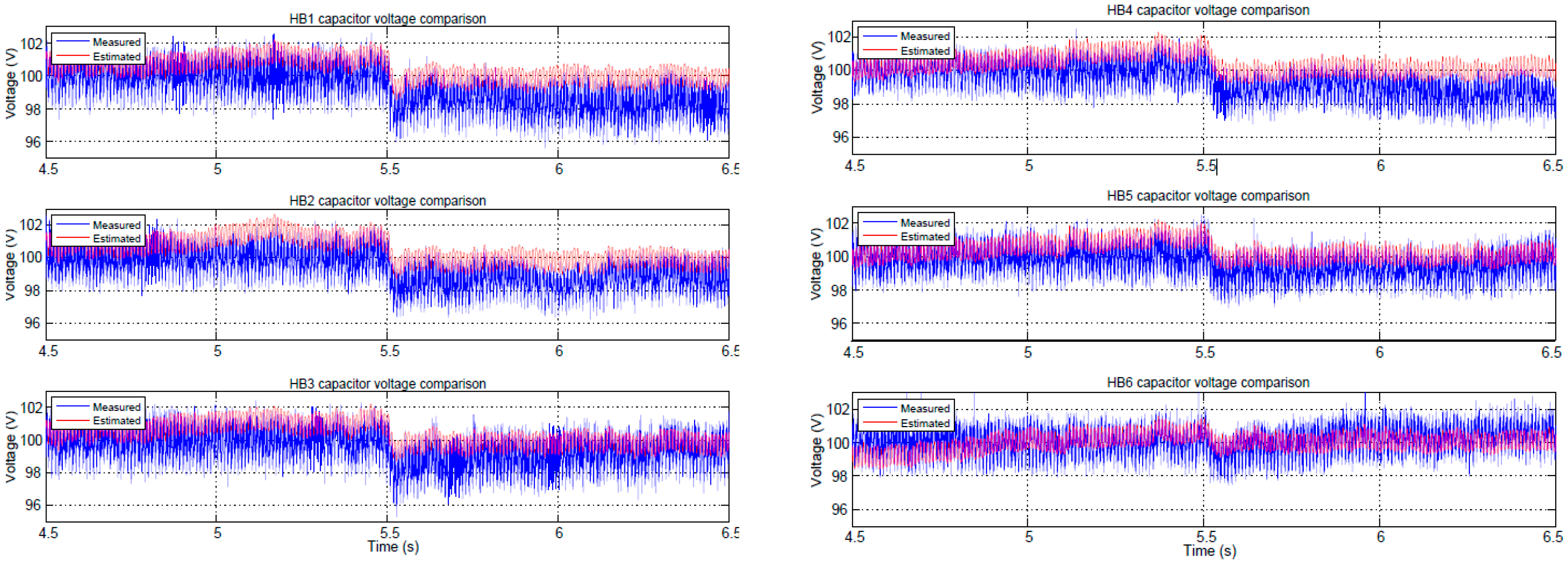
Figure 8 shows the capacitor voltages of all the MMC submodules before and after a failure occurring at the instant 5.5 s. This is an extreme case to show the performance of the eRTS estimate in such an unlikely situation. The fault in all voltage sensors is emulated by just switching the control feedback signals from those actually measured by the CIC filter to those provided by the eRTS at 5.5 s. In a real system, a fault detection algorithm would be used; however, as a proof of concept, here, the feedback signals are just switched by a software command.
One can notice from these results and from the error evolution in
Figure 9 that the system operates reliably after the fault. However, there is a slight drift in the actual voltage caused by a set of effects that were not considered in this work (nominal parameters instead of actual values, converter non-linearities, interlock delays and PWM resolution). However, it is clearly seen that the controller drives properly the eRTS voltage estimate to their 100 V reference. Additionally, according to
Figure 9, the estimation error is always kept under 10% of the nominal SM voltage for the whole test, which is acceptable with regards to the previous hypotheses. These results demonstrate that the eRTS can be used in the case of an extreme fault scenario, allowing the system to be shut down safely without compromising the converter integrity.
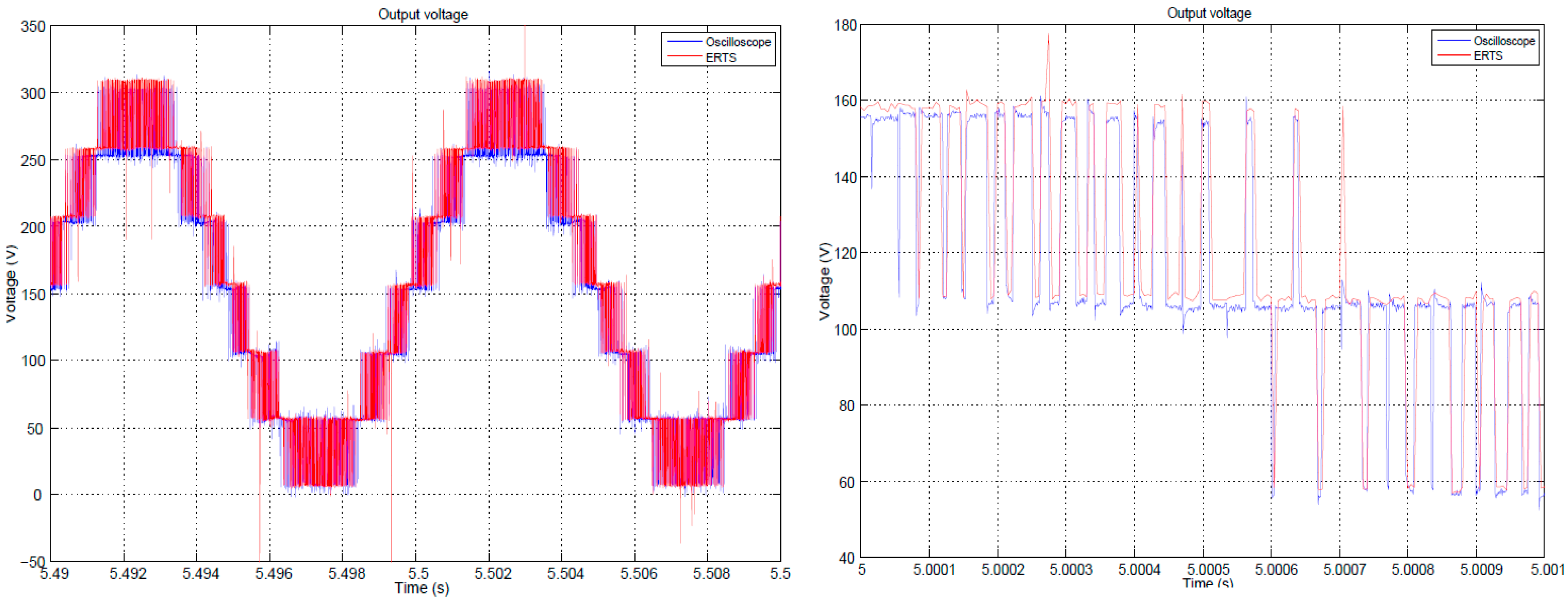
Figure 10 shows a comparison between the measured derivation branch voltage and the estimated one, which is obtained by using the eRTS-estimated capacitor voltages and the measured branch current. The captured data are obtained using a Yokogawa DL850 ScopeCorder oscilloscope sampling the signals at 1 µs, and the estimated output voltage is derived from the capacitor voltage eRTS and re-conditioned using MATLAB as a proof of concept. The shape of the signal is perfectly tracked, even when the eRTS is switched in at 5.5 s, with only a slight voltage difference when reaching the highest voltage magnitude. In the right side of the same figure, small differences are observed when the pulses are too short. This might be caused for two reasons: (i) the eRTS had insufficient time resolution (5 µs) to capture them; and/or (ii) the dead times introduced on each SM. Nevertheless, the reconstruction of the signal is good enough to be exploited, which might have interesting applications if the output voltage measurement fails.
6. Conclusions
This paper presented the development of a voltage sensorless controller of an MMC power converter. This controller integrates an eRTS that acts as a redundant block that estimates all the capacitor voltages of the MMC submodules. Hence, in the case of a faulty situation that occurs among the voltage sensors, the controller switches from the measured to the estimated quantities, which allows the overall system to continue operating.
After having detailed the used MMC topology, its associated control algorithm and the principle of the developed eRTS, authors presented the hardware/software implementation on the Xilinx Zynq-7020 SoC-FPGA. Indeed, having in mind the total algorithm complexity, the use of such a fully integrated technology was the best option, with a processing system where controller is coded, and a FPGA fabric where the eRTS, the PWM and the measurement chain are implemented.
The developed proof of concept was tested and validated in an experimental prototype in both healthy and faulty situations. The obtained results confirmed the level of estimation quality of the eRTS when compared to the measurements. Additionally, this eRTS operates properly when switching from the healthy to faulty case, which makes the overall voltage–sensorless control system work reliably.
These promising results encouraged the authors in conducting additional studies regarding the application of digital twins in the area of power electronics. One of the promising orientations of this work is the implementation of eRTS in the context of prognostics and health management of a power converter. In such a case, the eRTS capabilities must be enlarged in order to simulate the whole topology of the power converter and especially at the power switches level. However, the digital implementation challenges are strengthened since the fast transients occurring during a commutation must be finely approximated. Following these orientations, the first proof-of-concepts were developed and proposed in Ref. [
9].


 and
and 


