
Throughput Maximization for the Full-Duplex Two-Way Relay System with Energy Harvesting


School of Informatics, Xiamen University, Xiamen 361005, China
*
Author to whom correspondence should be addressed.
Electronics 2023, 12(1), 16; https://0-doi-org.brum.beds.ac.uk/10.3390/electronics12010016
Submission received: 2 November 2022
/
Revised: 18 November 2022
/
Accepted: 24 November 2022
/
Published: 21 December 2022
(This article belongs to the Special Issue Energy Harvesting and Energy Storage Systems, Volume II)
Abstract
:The full-duplex technique can improve the transmission capacity of the communication systems, and energy harvesting (EH) is a promising operation to prolong the lifespan of a wireless node by utilizing the radio-frequency signals. In this paper, the throughput performance of a full-duplex two-way energy EH capable relay system is investigated. In particular, a practical EH protocol, named the time-switching-based relaying (TSR) protocol, is used for EH and the decode-and-forward (DF) policy for information transmission. The outage probability is successfully obtained, and the corresponding system throughput for TSR protocol can be derived by it. The derived throughput is a function of different system parameters, including the time-switching (TS) ratio, power allocation ratio, and the length of the communication time slot. Meanwhile, the throughput is used to characterize a joint time and power allocation scheme for the system, and we aim to find the optimal time and power allocation to achieve the optimal throughput. Due to the existence of three variables and the integral form of throughput expression, an optimization for the throughput is difficult. However, a modified simulated annealing-based search (SABS) algorithm can be used to optimize the throughput. The modified SABS algorithm overcomes being highly impacted by the initial point, and derives the optimal solution fast. Simulation results show that the analytical throughput expression is related with the TS ratio, power allocation ratio, and the length of the communication time slot. The analytical curve of the throughput matches with the simulated one well, which shows that the obtained analytical system throughput for the TSR protocol is valid. Meanwhile, the proposed modified SABS algorithm could be used to derive accurate throughput when SNR is higher than 10 dB.
1. Introduction
Energy harvesting (EH), which enables network nodes to obtain energy from the controllable radio-frequency (RF) signal, is a promising technology that could significantly extend the lifespans of wireless networks [1]. Considering EH, although it has been shown that simultaneous energy and information transmission is optimal for using the RF energy in wireless systems [2], it is difficult to be implemented due to the limitation of current circuits. Therefore, a practical receiver protocol, named the time switching-based relaying (TSR) protocol is introduced [3,4,5,6]. The TSR protocol allows the relay node to switch either the information processing or the EH for the received RF signals at a time, which can be implemented easier [4].
On the other hand, the full-duplex technique could improve the throughput of communication systems by simultaneously transmitting and receiving signals in the same frequency band [7]. In the two-way relay system, the relay node is key to receive and forward the signal to the destination. If the relay node operates with a full-duplex, the system throughput will be enhanced [8,9]. Therefore, it is of great significance to investigate the full-duplex two-way relay system, where the relay node can perform both EH and full-duplex transmissions.
In this paper, we are interested in the throughput performance of the full-duplex (FD) two-way relay system, where the relay node can use RF signals to harvest energy. The relay node needs to simultaneously perform both full-duplex operation and energy harvesting, and it adopts the TSR protocol and the decode-and-forward (DF) policy for EH and full-duplex transmissions, respectively [10].
2. Related Works
There are a number of works that have considered the relay system and its performance analysis. In [11], though the relay node worked with a half-duplex, the authors presented a generalized approach to the performance analysis of relay-aided communication systems, and an expression of the outage probability that is valid for all fading scenarios. In fact, the outage probability is key to derive the system throughput [3,4,12]. Furthermore, a number of works have considered the full-duplex relay system design without energy harvesting [13,14]. In [13], the outage performance of the full-duplex relay system was investigated. In [14], the full-duplex cooperative cognitive radio network with multiple full-duplex secondary users was analyzed, and the optimal system throughput was derived. Since the EH technique was not used in these works, the system does not need to consider time or power allocation.
With energy harvesting, Refs. [15,16,17] further investigated the full-duplex relay system with the TSR protocol (TS-FDR-I protocol). In these papers, the system adopted the TSR protocol (TS-FDR-I protocol) so that it could optimize the time allocation to improve its own performance [15,16,17], and the system also optimized the power allocation for improving system performance [15,17]. In particular, with the TS-FDR-I protocol, the authors in [15] derived the optimal ergodic outage probability by considering different TS ratio, and the authors in [16] derived the optimal system throughput by optimizing the TS ratio. On the other hand, Refs. [15,17] considered the effect of power allocation, and the optimal ergodic outage probability was derived by optimizing the power allocation ratio.
2.1. Motivation
The aforementioned literature focused on the one-way relaying system, and only considered time allocation or power allocation. Compared with the FD one-way relay system, the outage probability and throughput calculation of the FD two-way relay system is more complicated, as we need to consider both destination nodes simultaneously [18,19]. In [18], the authors showed that the outage probability of FD two-way relay system consists of two complicated integral analytic expressions. Furthermore, a joint optimal transmission and power allocation scheme was proposed to improve the throughput of the relay networks [20], but it is difficult to be applied to the FD two-way relay system. Similarly, the authors in [21] used an alternating optimization method to optimize the outage and throughput performance of the full-duplex cooperative relaying system with EH. Its joint time and power allocation scheme is also difficult to be applied to our system. To the best of our knowledge, for the FD two-way relay system, Ref. [22] considered the system average rate analysis with power allocation, and Ref. [23] considered a joint transmit power and relay two-way beamforming optimization method to derive the system sum rate. Therefore, the throughput performance of the FD two-way EH capable relay system with joint time allocation and power allocation scheme is still to be solved, and we aim to propose a useful method to optimize the system throughput.
2.2. Contributions
In this paper, we give a comprehensive study on the throughput performance of the two-way energy harvesting relay system with full-duplex operation. In particular, we consider the joint time allocation and power allocation to maximize the network throughput of the two-way energy harvesting relay system. A new analytical method to obtain the outage probability is adopted, then the corresponding achievable system throughput is derived to characterize the joint time and power allocation scheme for the system. Based on the analytical expression, it is difficult to determine the optimal power allocation ratio and time allocation ratio because the complicated analytical expression contains three variables (TS ratio, power allocation ratio, and the length of communication time slot) and is in the integral form. For multiple variables optimization, the traditional exhaustive search method has high time complexity. To optimize the system throughput more efficiently, we further propose a simulated annealing based search (SABS) algorithm, and show that the close-to-optimal time and power allocation ratio that controls the trade-off between the energy and the information transmission can be efficiently obtained. The main contributions of this paper are summarized as follows:
- Using the DF policy, the signal-to-interference-plus-noise ratio (SINR) of the two-way system is derived. Therefore, the non-outage probability of the system can be calculated by these SINRs with a new analytical method.
- Using the derived non-outage probability, the system throughput expression is derived, which is further formulated as an optimization problem with three variables.
- A modified SABS algorithm is used to solve the throughput optimization problem. The algorithm is not dependent on the selection of the initial point.
- Simulation results show that the analytical throughput matches well with the simulated throughput, and the biggest gap between the analytical throughput with the simulated throughput is . Furthermore, the results derived by the modified SABS algorithm is accurate when the SNR varies from 10 dB to 40 dB.
The remainder of this paper is organized as follows: Section 2 introduces the full-duplex system model. Section 3 presents the system throughput and proposes the modified simulated annealing based search algorithm. In Section 4, we present the simulation results. Finally, Section 5 concludes the paper.
3. System Model
A full-duplex two-way EH relaying system is considered, which consists of two terminal nodes S and D, and one relay node R, as shown in Figure 1. The direct path between S and D is ignored. Thus, S and D exchange information with the help of the relay node, which is energy-constrained. The relay node R adopts decode and forward (DF) in the full-duplex transmission. With the energy harvesting technique, node R can harvest energy by the RF signals transmitted from S and D for forwarding information. We assume that the information processing energy consumed by R is negligible, compared with the transmit energy. With the FD technique, the information exchange between S and D can be completed in two time slots.
Let denote the channel gains of the links in the FD two-way relay system, and denote the channel gains of the self-interference link. A reasonable assumption is that all the channel gains do not change during the transmission block time T, which are independent and identically distributed from one block to the next. Furthermore, we assume that follow Rayleigh distribution and follow Gaussian distribution.
In this paper, we focus on the TS-FDR-I protocol [17], which can be implemented easily in practice. In the TS-FDR-I protocol, the information exchange is completed with two phases. In the first phase, S and D transmit to R for energy harvesting. In the second phase, it is further divided into two slots for information transmission of S-D and D-S, respectively. Let and denote the time allocation factor for energy harvesting and the time allocation factor between the two link information transmission, respectively. Thus, the time allocation of TS-FDR-I protocol is given as follows:
where and denote the two full-duplex information transmission processes. For finding notations of this paper more conveniently, the key notations are listed in Table 1.
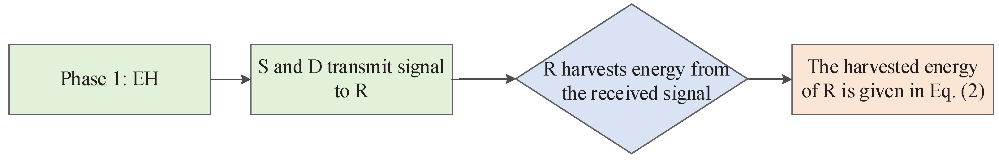
3.1. Phase 1 (Energy Harvesting)
In the first phase, S and D transmit normalized signals and to R with powers and , respectively. Without loss of generality, suppose that . The received signal at R is
where is the additive Gaussian noise at the relay node. In Phase 1, the time duration for EH is . Thus, the harvested energy at node R is given by
where is the energy conversion efficiency, which depends on the EH technology. Figure 2 shows a intuitive energy-harvesting process.
3.2. Phase 2 (Information Processing)
In this phase, S and D exchange their own information by R. Therefore, relay node R allocates a part of its harvested energy (in phase 1) to help S transmit the signal to D, and the remaining harvested energy of R is used to finish transmitting the signal from D to S. The intuitive information process is showed in Figure 3.
3.2.1. S Transmits Signal to D
In the second phase, S first continues to transmit signal , and R transmits to D with the harvested energy in the previous phase. Notice that the received signal at R not only includes the signal from S, but also includes the self-interference by R. Thus, the received signal at R is given by
where is the additive Gaussian noise, and is the relay transmit signal satisfying . Since the time duration for information transmission from R to D is , if part of the harvested energy is allocated to this link (the allocated factor is ), the transmission power of R can be computed as follows [15]:
In the full-duplex relaying system, the relay node usually applies the self-interference cancellation technology to reduce the loop-back interference [24,25]. Therefore, after the interference cancellation and sampling, the post-cancellation sampled signal is given by
where is the residual loop-back interference channel coefficient caused by imperfect cancellation. Because the relay node uses the DF policy for information transmission, it will first decode the original source signal and then regenerate the signal. Hence, the relay transmit signal can be expressed as , where is the processing delay at the relay [26]. Furthermore, let denote with a noise power of .
The final received signal at D is
where is the noise introduced at D. The power of noise is denoted by .
3.2.2. D Transmits Signal to S
Since the time duration for D to S link is and all the remaining harvested energy is used by R, the transmission power of R is given by
Following a similar analysis of , we can show that the received signal at R is given by
where is the residual loop-back interference channel coefficient, and () is the relay transmit signal. In particular, with a noise power of .
After information processing, R forwards the signal to S and the final received signal at S is
where is the noise introduced at S. The power of noise is denoted by .
We assume that . Therefore, the signal-to-interference-plus-noise ratio (SINR) at S, R and D is given by
4. Throughput Analysis
In this section, we derive the analytical achievable throughput of the FD two-way system with EH. For the full-duplex system with the DF policy, we first need to derive the expression of outage probability, and then compute the achievable throughput.
4.1. Achievable Throughput
Let denote the required SINR threshold for correct reception with transmission rate U, i.e., . Since the relay uses the DF relaying policy, the outage probability is given by
The above equation shows that the outage probability of the full-duplex system in the DF relaying scheme consists of four components. Next, we will show how to compute each component in (14).
The non-outage probability is given by
Since and follow Rayleigh distribution, and are exponential random variables with mean values of and , respectively. Thus, we have
Similarly, the non-outage probability is given by
When R forwards signal to D, the non-outage probability at D is given by
and its analytical expression could be derived by the following proposition.
Proposition 1.
If , the non-outage probability , defined in (18), is given by
where the notation denotes the nth order modified Bessel function of the second kind.
If , the non-outage probability at D is given by
Proof.
See Appendix A. □
Similarly, the expression of the non-outage probability at S is shown as follows: If ,
If ,
Finally, the achievable system throughput is given by
4.2. System Throughput Optimization
In the energy harvesting FD two-way relay system, we aim to optimize the time and power allocation to maximize the system throughput. In particular, it can be formulated as the following optimization problem:
However, problem (24) contains three variables and is in the integral form which make problem (24) difficult to solve. The exhaustive search method for all three variables has high time complexity, and this motivates us to propose a simulated annealing based search (SABS) algorithm to obtain the optimal system configuration parameters that maximize system throughput. Note that the SABS algorithm is very dependent on the selection of the initial point. To overcome this problem, we improve its performance using the principle of alternating optimization, i.e, deriving and by exhaustive search and SABS, respectively.
Solving problem (24) by the modified SABS algorithm, we first set initial value of and randomly, and obtain the optimal value of by exhaustive search (see the step 1 of Algorithm 1). Then we construct the vector solution , where is the solution space consisting of , and . In step 3 of Algorithm 1, we design an accept probability which could help select the alternative point as the next iteration point. The accepted probability is given by
where is a sequence of positive numbers, i.e., is cooling schedule [27]. From the accepted probability, we could observe that if , the value of is equal to 1, which means . Furthermore, although , the probability that is . Generally, cooling schedule monotonically decreases to 0, and this denotes the cooling process. In Algorithm 1, is given by
where denotes the initial temperature.
| Algorithm 1 The modified simulated annealing based search algorithm |
Input:, , , , , J and K Output:the optimal , , 1Derive the value of by exhaustive search with β and θ; 2Initialize value ; 3Select an alternative point at random from Ω; 4Design a random event, and the probability of the event happening is ; 5Perform the event. If the event occurred, let ; Otherwise, let ; 6If and , ; 7Let and return to step 3; 8If , return to step 1; otherwise, the algorithm terminates; |
In Algorithm 1, it is worth noting that the larger the gap between and , the more impossible is selected as the next iteration point. Similarly, the smaller is, the less likely is to be selected as an iteration point. In other words, Algorithm 1 first searches the optimal solution from the overall solution space . As k increases, the search scope will concentrate to the vicinity of the global optimal point. Meanwhile, the computational complexity of the Algorithm 1 in terms of the number of variables and the loops is . Deriving the and , Algorithm 1 returns to step 1 and repeats the above process. Compared with the exhaustive search and the classical SABS algorithm, Algorithm 1 not only improves the search efficiency significantly, but also no longer depends on the selection of the initial point.
5. Numerical Results and Simulation
In this section, the throughput of this system is investigated. Furthermore, we compare the analytical results with simulated results for proving the analytical framework. Unless otherwise specified, the parameters in the simulation are set as follows: W, 3 bits/s/Hz, , [12], , W.
5.1. Model Validation
Figure 4 shows the analytical throughput and the simulated throughput of the full-duplex system. We find that the analytical throughput matches well with the simulated throughput. Furthermore, we can find that the system throughput varies with different parameters, including , and .
5.1.1. The Effect of
Figure 4a shows the system throughput as a function of when the other two parameters are set as and . For the analytical results of , we set W, W. We can observe that the biggest gap between the analytical throughput and the simulated throughput is when . For the analytical results of , we set W. The biggest gap between the analytical throughput and the simulated throughput is when . These results show that the analytical throughput reflects the practical throughput well. On the other hand, the system throughput first increases and then decreases as increases. This is because that when is too small, the harvested energy at R is not enough, so the transmitted energy for R is also not enough. When is close to 1, the harvested energy at R is large. However, the time for information transmission is reduced, which leads to a decrease in the system throughput, too.
5.1.2. The Effect of
Figure 4b shows the system throughput as a function of when the other two parameters are set as and . The analytical results are also close to the simulated throughput. When is very small, the energy for the link S-D is small, and this will make the transmission from S to D fail, and thus, the throughput will become small; otherwise, when is very large, the energy for the link D-S is small, and this will make the transmission from D to S fail. Thus, the throughput will also become small.
5.1.3. The Effect of
5.2. The Non-Outage Probability
In fact, the non-outage probability is the key to obtain the system throughput. Figure 5 shows that the non-outage probability is related with SNR, and its value ranges from 0 to 1. The effect of noise power variation is equivalent to the effect of the transmission power variation, and it could be observed that the non-outage probability increases with the increases in SNR, i.e., the larger transmission power brings a larger non-outage probability. Meanwhile, Figure 5 shows that there is little gap between optimal non-outage probability and non-outage probability with fixed system parameters. Thus, we cannot optimize the non-outage probability alone, but should further consider optimizing the system throughput.
5.3. The Optimal Throughput
We further investigate the optimal throughput of the full-duplex system. From Figure 6a, we find that the system throughput of fixed parameters is smaller than the practical optimal throughput. In Figure 6b, we give the comparison of practical throughput with the throughput derived by different methods, and we set the search step length for the exhaustive search method. We can observe that the throughput of these two methods is relatively accurate when SNR varies from 10 dB to 40 dB. The throughput derived by the exhaustive search method or Algorithm 1 has the biggest gap between the practical throughput when SNR is 10 dB.
6. Conclusions
In this paper, a joint time and power allocation scheme for the FD two-way EH-capable relay system from the perspective of system throughput is investigated. Considering the system using DF policy to transmit information, the SINRs at S, R and D are first derived. Thus, the non-outage probability of the system can be obtained by these SINRs. Furthermore, a new analytical method is used to obtain the non-outage probability so that the corresponding system throughput can be derived. We find that the system throughput contained three variables, i.e., time switching ratio, power allocation ratio, and the length of communication time slot, and is in the integral form. To achieve the optimal system throughput, these three variables need to be optimized simultaneously. Since the traditional exhaustive search method has high time complexity for solving the problem with multiple variables, we propose a modified SABS algorithm that could efficiently find the close-to-optimal time and power allocation to maximize throughput. Numerical results are provided to demonstrate the accuracy and the effectiveness of our new analytical framework, and they show that the SABS algorithm can derive accurate throughput results.
Author Contributions
Writing—original draft preparation, K.Z.; writing—review, L.F. All authors have read and agreed to the published version of the manuscript.
Funding
This research received no external funding.
Data Availability Statement
The raw data supporting the conclusion of this article will be made available by the authors without undue reservation.
Conflicts of Interest
The authors declare no conflict of interest.
Appendix A
Proof of Proposition 1.
. Let , and we can derive the probability distribution function (PDF) of Z:
Thus, the non-outage probability at D is given by
where denotes the nth order modified Bessel function of the second kind. Meanwhile, equation is used.
. Let , and the PDF of Z could be given by
Thus, the non-outage probability at node D is given by
where the equation is used. □
References
- Hu, S.; Chen, X.; Ni, W.; Wang, X.; Hossain, E. Modeling and analysis of energy harvesting and smart grid-powered wireless communication networks: A contemporary survey. IEEE Trans. Green Commun. Netw. 2020, 4, 461–496. [Google Scholar] [CrossRef] [Green Version]
- Zhong, C.; Suraweera, H.A.; Zheng, G.; Krikidis, I.; Zhang, Z. Improving the throughput of wireless powered dual-hop systems with Full Duplex relaying. In Proceedings of the 2015 IEEE International Conference on Communications (ICC), London, UK, 8–12 June 2015. [Google Scholar]
- Atapattu, S.; Evans, J. Optimal energy harvesting protocols for wireless relay networks. IEEE Trans. Wirel. Commun. 2016, 15, 5789–5803. [Google Scholar] [CrossRef]
- Nasir, A.A.; Zhou, X.; Durrani, S.; Kennedy, R.A. Relaying protocols for wireless energy harvesting and information processing. IEEE Trans. Wirel. Commun. 2013, 12, 3622–3636. [Google Scholar] [CrossRef] [Green Version]
- Xun, Z.; Rui, Z.; Ho, C.K. Wireless information and power transfer: Architecture design and rate-energy tradeoff. IEEE Trans. Commun. 2013, 61, 4754–4767. [Google Scholar]
- Singh, D.; Ouamri, M.A.; Alzaidi, M.S.; Alharbi, T.E.A.; Ghoneim, S.S.M. Performance analysis of wireless power transfer enabled dual hop relay system under generalised fading scenarios. IEEE Access 2022, 10, 114364–114373. [Google Scholar] [CrossRef]
- Kolodziej, K.E.; Perry, B.T.; Herd, J.S. In-band full-duplex technology: Techniques and systems survey. IEEE Trans. Microw. Theory Tech. 2020, 67, 3025–3041. [Google Scholar] [CrossRef]
- Wang, D.; Zhang, R.; Cheng, X.; Yang, L.; Chen, C. Relay selection in full-duplex energy-harvesting two-way relay networks. IEEE Trans. Green Commun. Netw. 2017, 1, 182–191. [Google Scholar] [CrossRef]
- Nguyen, B.C.; Tran, X.N.; Tran, D.T. Performance analysis of full-duplex decode-and-forward two-way relay networks with transceiver impairments. Ann. Telecommun. 2022, 77, 187–200. [Google Scholar] [CrossRef]
- Gu, Y.; Aïssa, S. RF-based energy harvesting in Decode-and-Forward relaying systems: Ergodic and outage capacities. IEEE Trans. Wirel. Commun. 2018, 14, 6425–6434. [Google Scholar] [CrossRef] [Green Version]
- Singh, D.; Ouamri, M.A.; Muthanna, M.S.A.; Adam, A.B.M.; Muthanna, A.; Koucheryavy, A.; El-Latif, A.A.A. A generalized approach on outage performance analysis of dual-hop decode and forward relaying for 5G and beyond scenarios. Sustainability 2022, 14, 12870. [Google Scholar] [CrossRef]
- Cao, H.; Fu, L.; Dai, H. Throughput analysis of the two-way relay system with network coding and energy harvesting. In Proceedings of the 2017 IEEE International Conference on Communications (ICC), Paris, France, 21–25 May 2017. [Google Scholar]
- Khafagy, M.; Ismail, A.; Alouini, M.; Aissa, S. On the outage performance of full-duplex selective decode-and-forward relaying. IEEE Commun. Lett. 2013, 17, 1180–1183. [Google Scholar] [CrossRef]
- Ozfatura, M.E.; Elazzouni, S.; Ercetin, O.; Elbatt, T. Optimal throughput performance in full-duplex relay assisted cognitive networks. Wirel. Netw. 2018, 25, 1931–1947. [Google Scholar] [CrossRef]
- Rabie, K.M.; Adebisi, B.; Alouini, M.S. Half-Duplex and Full-Duplex AF and DF relaying with Energy-Harvesting in Log-Normal fading. IEEE Trans. Green Commun. Netw. 2017, 1, 468–480. [Google Scholar] [CrossRef] [Green Version]
- Zhong, K.; Fu, L. Optimal throughput of the full-duplex two-way relay system with energy harvesting. In Proceedings of the 2021 IEEE 94th Vehicular Technology Conference (VTC2021-Fall), Norman, OK, USA, 27–30 September 2021. [Google Scholar]
- Wang, D.; Zhang, R.; Xiang, C.; Yang, L. Capacity-enhancing Full-Duplex relay networks based on power splitting (PS-)SWIPT. IEEE Trans. Veh. Technol. 2017, 66, 5445–5450. [Google Scholar] [CrossRef]
- Hu, R.; Hu, C.; Jiang, J.; Xie, X.; Song, L. Full-Duplex mode in Amplify-and-Forward relay channels: Outage probability and ergodic capacity. Int. J. Antennas Propag. 2014, 2014, 347540. [Google Scholar] [CrossRef] [Green Version]
- Zhang, Z.; Ma, Z.; Ding, Z.; Xiao, M.; Karagiannidis, G.K. Full-duplex two-way and one-way relaying: Average rate, outage probability, and tradeoffs. IEEE Trans. Wirel. Commun. 2016, 15, 3920–3933. [Google Scholar] [CrossRef]
- Lin, J.-Y.; Chang, R.Y.; Tsao, H.-W.; Su, H.-J. Energy harvesting-enabled full-duplex DF relay systems with improper gaussian signaling. In Proceedings of the 2020 IEEE Wireless Communications and Networking Conference (WCNC), Seoul, Republic of Korea, 25–28 May 2020. [Google Scholar]
- Aswathi, V.; Babu, A.V. Outage and throughput analysis of full-duplex cooperative NOMA system with energy harvesting. IEEE Trans. Veh. Technol. 2021, 70, 11648–11664. [Google Scholar] [CrossRef]
- Cheng, X.; Yu, B.; Cheng, X.; Yang, L. Two-Way Full-Duplex Amplify-and-Forward relaying. In Proceedings of the MILCOM 2013–2013 IEEE Military Communications Conference, San Diego, CA, USA, 18–20 November 2013. [Google Scholar]
- Okandeji, A.; Khandaker, M.; Wong, K.-K.; Zheng, Z. Joint transmit power and relay two-way beamforming optimization for energy-harvesting full-duplex communications. In Proceedings of the 2016 IEEE Globecom Workshops (GC Wkshps), Washington, DC, USA, 4–8 December 2016. [Google Scholar]
- Bharadia, D.; Mcmilin, E.; Katti, S. Full Duplex radios. In Proceedings of the ACM SIGCOMM 2013 Conference, Hong Kong, China, 12–16 August 2013. [Google Scholar]
- He, Y.; Zhao, H.; Guo, W.; Shao, S.; Tang, Y. Frequency-domain successive cancellation of nonlinear self-interference with reduced complexity for full-duplex radios. IEEE Trans. Commun. 2022, 70, 2678–2690. [Google Scholar] [CrossRef]
- Liu, H.; Kim, K.J.; Kwak, K.S.; Vincent Poor, H. Power splitting-based SWIPT with Decode-and-Forward Full-Duplex relaying. IEEE Trans. Wirel. Commun. 2016, 15, 7561–7577. [Google Scholar] [CrossRef]
- Hajek, B. Cooling schedules for optimal annealing. Math. Oper. Res. 1987, 13, 311–329. [Google Scholar] [CrossRef]
Figure 1.
Full-duplex two-way relay system.

Figure 2.
The flow chart of EH.

Figure 3.
The flow chart of information processing.

Figure 4.
The system throughput as a function of , , and . Other parameter . (a) Throughput as a function of . (b) Throughput as a function of . (c) Throughput as a function of .
Figure 4.
The system throughput as a function of , , and . Other parameter . (a) Throughput as a function of . (b) Throughput as a function of . (c) Throughput as a function of .

Figure 5.
The non-outage probability as a function of noise power.

Figure 6.
Optimal throughput as a function of noise power. (a) Optimal throughput vs. throughput with fixed system parameters. (b) The throughput obtained by different methods.
Figure 6.
Optimal throughput as a function of noise power. (a) Optimal throughput vs. throughput with fixed system parameters. (b) The throughput obtained by different methods.


Table 1.
Notation setting.
| Notation | Physical Meaning |
|---|---|
| channel gains of the two-way links (Rayleigh distribution) | |
| channel gains of the self-interference channel (Gaussian distribution) | |
| the residual loop-back interference channel coefficient | |
| time-switching ratio | |
| power allocation ratio | |
| deciding the length of communication time slot for per phase | |
| T | the total communication time |
| , | normalized signals transmitted by S and D |
| , | transmission power of S and D |
| the energy conversion efficiency | |
| , | signals transmitted by R |
| , | transmission power of R in phase 1 and phase 2 |
| noise symbol | |
| noise power | |
| the derived SINR | |
| the required SINR threshold | |
| U | signal transmission rate |
| the non-outage probability | |
| the outage probability of the system | |
| the achievable system throughput | |
| mean values of the exponential random variables |
Disclaimer/Publisher’s Note: The statements, opinions and data contained in all publications are solely those of the individual author(s) and contributor(s) and not of MDPI and/or the editor(s). MDPI and/or the editor(s) disclaim responsibility for any injury to people or property resulting from any ideas, methods, instructions or products referred to in the content. |
© 2022 by the authors. Licensee MDPI, Basel, Switzerland. This article is an open access article distributed under the terms and conditions of the Creative Commons Attribution (CC BY) license (https://creativecommons.org/licenses/by/4.0/).
Share and Cite
MDPI and ACS Style
Zhong, K.; Fu, L. Throughput Maximization for the Full-Duplex Two-Way Relay System with Energy Harvesting. Electronics 2023, 12, 16. https://0-doi-org.brum.beds.ac.uk/10.3390/electronics12010016
AMA Style
Zhong K, Fu L. Throughput Maximization for the Full-Duplex Two-Way Relay System with Energy Harvesting. Electronics. 2023; 12(1):16. https://0-doi-org.brum.beds.ac.uk/10.3390/electronics12010016
Chicago/Turabian StyleZhong, Kaiqi, and Liqun Fu. 2023. "Throughput Maximization for the Full-Duplex Two-Way Relay System with Energy Harvesting" Electronics 12, no. 1: 16. https://0-doi-org.brum.beds.ac.uk/10.3390/electronics12010016
Note that from the first issue of 2016, this journal uses article numbers instead of page numbers. See further details here.