Article

A Two-Degree-of-Freedom PID Integral Super-Twisting Controller Based on Atom Search Optimizer Applied to DC-DC Interleaved Converters for Fuel Cell Applications

by
Ramzi Saadi
1,2,*,
Mohamed Yacine Hammoudi
1,2,
Okba Salah
1,2,
Khaled Laadjal
2,* and
Antonio J. Marques Cardoso
2
1
MSE Laboratory, Department of Electrical Engineering, Mohamed Khider University, Biskra 7000, Algeria
2
CISE—Electromechatronic Systems Research Centre, University of Beira Interior, Calçada Fonte do Lameiro, P-6201-001 Covilhã, Portugal
*
Authors to whom correspondence should be addressed.
Submission received: 18 August 2023 / Revised: 26 September 2023 / Accepted: 27 September 2023 / Published: 1 October 2023

Abstract

:
This paper focuses on the real-time implementation of an optimal high-performance control applied to an interleaved nonisolated DC/DC converter designed for fuel cell applications. Three-phase interleaved boost converters are utilized to minimize input current undulation, increase efficiency, and provide a high output voltage in order to ensure the performance of the FC stack. The proposed control strategy contains an outer loop that generates the reference current based on a two-degree-of-freedom PID controller. This controller provides a robust setpoint tracking and disturbance rejection, which improves the system’s response and efficiency. A fast inner regulation loop based on a super-twisting integral sliding mode (STISM) algorithm is developed to achieve a fixed converter output voltage, equitable phase current sharing, and fast regulation against load disturbances in failure operation. The STISM algorithm exhibits a rapid convergence property of the sliding mode and effectively avoids the chattering phenomena frequently observed in conventional sliding modes. The proposed controller’s gains are determined using the atom search optimization algorithm, which ensures exceptional reliability and a high degree of robustness and stability of the controllers under a variety of operational conditions. This method is inspired from the behavior of atoms and their electrons during the excitation process leading to a one-of-a-kind optimization technique which contributes to the controller’s reliability. Using Matlab-Simulink simulation tools, the efficacy and performance of the designed control have first been evaluated and assessed and compared with other optimization algorithms, and then with a dual loop based on a PID controller. Then, they have been verified by real-time hardware implementation on a 1.2 KW prototype FC converter driven by the dSPACE-1104 card under a variety of tests. The suggested approach offers impressive experimental results in dynamic and steady states.

1. Introduction

Fuel cells (FCs) are one of the promising potential alternatives to cope with the problem of air pollution and the decrease in fossil fuel reserves, since they offer a clean and effective power generation source. Such technology provides several applications, including, but not limited to stationary power generation, transportation, and backup power systems. Fuel cells are electrochemical systems that efficiently convert chemical energy (from hydrogen-rich fuel gas) directly into electrical energy [1]. The only by-products of the conversion process are water and heat. FCs provide various advantages compared with conventional fuel sources, including enhanced effectiveness, quiet operation, a low heating rate, high energy density, and reduced emissions [2,3].
From the various existing FC types, the proton exchange membrane fuel cells (PEMFCs) are presented as the most appropriate candidate for electric vehicles and stationary applications since they provide numerous benefits [4,5], including solid electrolyte, an adequate compactness, minimal corrosion, and the outflow of water liquid at the output, which all contribute to environmental sustainability [6].
FCs are described as low voltage–high current energy sources, and typically produce a very low output voltage of around 1 volt. As a consequence, single cells must be connected in series to build an FC stack. Nevertheless, the number of cells stacked in series should be restricted, since stacking more cells in series reduces FC efficiency and lifetime. As a result, voltage-controlled conditioning systems such DC/DC converters are essential for fuel cell applications. It is necessary to raise the low voltage generated by PEMFCs to a high and regular operating voltage [7]. In addition, these DC/DC converters are employed to obtain a constant DC bus despite the PEMFC output voltage, which is heavily affected due to load variation.
The main challenge of a DC-DC converter designed for FC application is to ensure a high output voltage and low input current undulation, while excessive current undulation reduces the PEMFC lifespan. Another property of a current ripple is that it impacts not only the lifetime, but also the volume and fuel economy. It has been presented in the literature that current undulation must be minimized to less than 10% of the average FC current [8,9,10]. Moreover, the size, mass, cost, power density, and effectiveness of a DC-DC converter are critical performance parameters for the design of an FC DC-DC converter [11]. Earlier studies examining DC-DC converter topologies for FC applications [12,13] noted that conventional boost converters have significant drawbacks and fail to match the requirements of DC-DC converters for PEMFC applications [14]. Hence, the use of the interleaved converter (IBC) may provide improved efficiency, enhanced reliability, and PEMFC lifespan extension through a low input current ripple in both normal and degraded operation conditions, compactness, and minimal electromagnetic disruption. Hence, a number of published studies on IBC for PEMFC applications have emerged [15,16,17].
However, the design of controller for an IBC suitable for FC applications is more challenging from the standpoint of robustness and stability. There are several issues to consider, which include load disturbance rejection, limiting FC current undulation, overshoots, and settling time. This would impose additional performance constraints on the controller. The nonlinearity of the FC stack and the double pole and right half plane (RHP) zero, which is incorporated in the converter transfer function from the duty cycle to the output voltage, increase the complexity of the controller design [18]. On this topic, numerous studies on DC/DC converter control schemes for PEMFC power systems have been conducted. Ref [19] introduced a dual loop proportional–integral controller (PI) to regulate the DC bus voltage of the interleaved converter and demonstrated that the effectiveness of the PI control developed on the basis of the nominal condition ensures stability around a specific steady operating point. In [20], a linear quadratic regulator (LQR) based on the state-space averaged model for FC IBC converters is developed; however, this approach suffers from restricted and inefficient effectiveness across a wide load range. In [21], a control based on the Hamiltonian control is formed for an IBC PEMFC converter. The proposed controller needs reliable information about the converter model. The authors of [22] presented the application of a multi-loop controller which contains an active disturbance rejection control (ADRC) voltage loop and a sliding super-twisting (STSM) inner current loop. The suggested controller’s reliability was examined and confirmed by both experimental and simulation tests, and the ADRC outer loop ensured the entire system’s insensitivity and robustness. The main disadvantage was that the current loop using conventional STSM control might raise the FC current ripple, which could lead to a high-frequency system disturbance. W. Thammasiriroj et al., in [23], designed a nonlinear closed-loop control based on the flatness theory, which provides an alternative option for reference tracking without employing a complex algorithm. The lack of an inner current regulation loop renders it hard to reach the current limitation that is required for PEMFC applications. It signifies that the current is monitored, but not regulated, which decreases FC cell lifetime. In [24], a model for predictive control is developed for an IBC converter, which was validated via simulation results only. The effectiveness of model predictive control techniques is strongly influenced when there are unknown changes in the system parameters or when the system model is not fully developed. Furthermore, the main weakness of the approach is that the computational burden might present significant limitations on the practical implementation. Even though numerous controllers based on various approaches have been proposed and verified in the literature, including robust adaptive ADRC control [25], adaptive feedback control [26,27], model-free control [28], and other techniques for an FC system converter, there is still potential for enhancement. Nevertheless, the optimal design of FC IBC controllers in terms of robustness and optimal performance was not examined among the presented state-of-the-art control strategies, whose sole objective is to ensure system stability.
In this article, an innovative and effective cascade-loop voltage current controller is developed for IBC FC conversion. The proposed controller architecture is composed of two loops: an outer voltage control loop and an inner current loop. The voltage loop is controlled by using the two-degree-of-freedom proportional-integral derivative (2DOFPID) control [29,30] to improve the system robustness, disturbance rejection, and insensitivity. The 2DOFPID controller is utilized due to its aptitude for simultaneously handling the set point tracking and disturbance rejection. Several researchers have evaluated this control scheme in different fields of engineering [31,32,33,34]. For the inner current loop, a nonlinear higher-order super-twisting integral sliding controller (STISM) [35] is adopted to achieve a robust and fast reference current regulation. The designed STISM inner loop, which is based on the high-order sliding mode technique, is very robust against external disturbances that change over time. It also overcomes the chattering phenomena and ensures fast convergence with improved tracking performance.
The major contributions of this study can be defined as follows:
  • The use of an improved topology utilizing a three-phase DC-DC converter, instead of the conventional boost converter, has been proposed for the purpose of enhancing fuel cell output regulation.
  • The design and implementation of a new robust dual-loop controller based on 2DOFPID for the voltage loop and STISM for the current loop was developed for DC bus voltage regulation of a PEMFC IBC converter.
  • The tuning of optimal parameters of the suggested dual-loop controller are identified through atom search (ASO)-based optimal design. The ASO tuning optimizer was compared with two other optimization approaches that have been recently reported in the literature.
  • A comparison is made between the proposed ASO-2DOFPID- STISM controller and the ASO-based PID controller.
  • A 1.2 k watt test bench has been developed to carry out the performance evaluation of the suggested dual-loop controller.
The subsequent sections of the paper are structured as follows: In Section 2, a brief presentation of the PEMFC three-phase IBC converter is provided. The modelling of the PEMFC-IBC system is introduced in Section 3. In the next section, the proposed optimal cascade loop is designed. Section 5 illustrates the performance validation and simulation results, while Section 6 presents the experimental results. Finally, the conclusion is the last part of the paper.

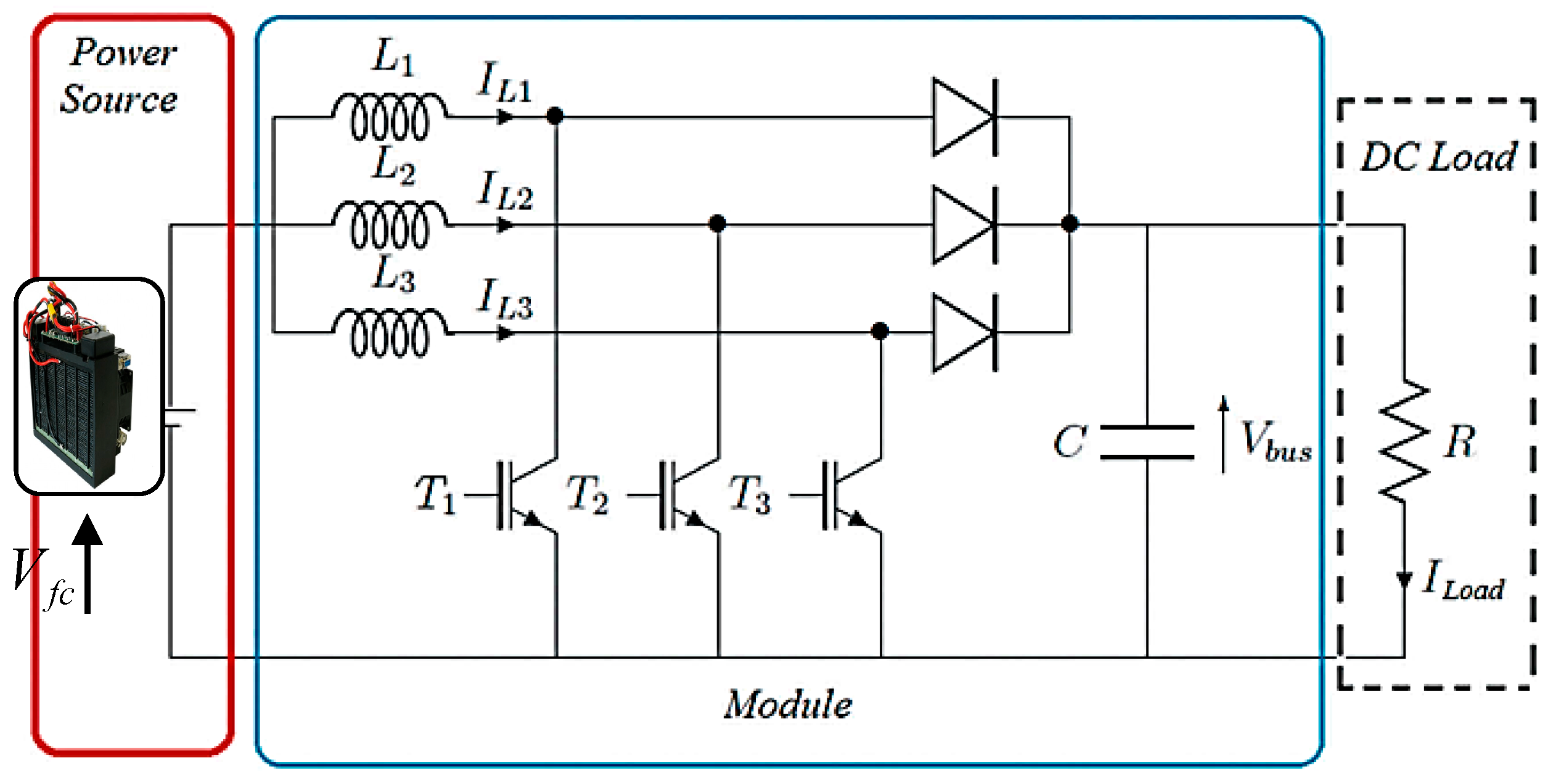
2. Presentation of the PEMFC Three-Phase IBC Converter

In order to fulfil the specifications of the PEMFC, three-phase IBC architecture [36,37] has been employed in the current research. Figure 1 illustrates the circuit schematic of the IBC converter, which is powered using a proton exchange membrane fuel cell (pEMFC). The interleaved boost converter (IBC) is composed of up to N-interleaved boost converters that are connected in parallel and share a single DC bus. The adoption of the interleaving method can be achieved through the parallel interconnection of the converter legs at the input. This technique provides multiple benefits, including a reduced ripple rate in the input current, increased effectiveness, reliability, compactness, and lowered current stress on the electronic device [38]. The number of legs are determined by a balanced evaluation considering current undulation, inductor size, and effectiveness.
Figure 2 illustrates the fluctuation of the value of the input current ripple ( Δ i f c / Δ i L ) as a function of the duty cycle.
Here, Δ i f c   indicates the fuel cell current ripple and Δ i L   indicates the inductor current ripple.
From this figure, the choice of this specific architecture is further justified according to its ability to eliminate ripple currents during particular duty cycles. The three-phase IBC exhibits two duty cycle values at which the input current ripple is eliminated, compared with two-phase IBC and conventional boost converters.
Figure 3 illustrates the efficiency of the three-phase IBC converter in relation to the current of the PEMFC. Analyzing Figure 3, one can observe that a three-phase FIBC preserves excellent efficiency throughout a wide range of power demands compared with a conventional boost converter.

3. Modelling of the PEMFC-IBC System

3.1. Mathematical Model of the PEMFC

The model under consideration in this study was presented in [39], which is frequently referenced in academic research, is founded on the formulas by Nernst and Tafel. As a result, the voltage of a single cell is expressed as follows [39]:
E c e l l = E 0 η a c t η o h m η c o n c
where E0 is the thermodynamic potential of the cell and is defined as [33]:
E 0 = 1.229 0.58 × 1 0 3 T c e l l 298.15 + 4.3085 × l n ( P H 2 ) + 1 2 l n ( P O 2 )
where Tcell indicates the temperature of the cell and is approximately 328 K. PH2 is the relative pressure of hydrogen, and PO2 is the relative pressure of oxygen.
The simple equation that has been used to describe the activation voltage is written as [40]
η a c t = ζ 1 + ζ 2 T c e l l + ζ 3 T c e l l l n C a 2 + ζ 4 T c e l l l n I c e l l
The abbreviation I c e l l refers to the fuel cell stack current. ζ 1 , ζ 2 , ζ 3 ,   a n d   ζ 4 are constants defined as [40]:
ζ 1 = 0.948 ζ 2 = k f c c e l l + 0.197 × 1 0 3 l n ( A a ) + 4.3 × 1 0 5 l n ( C H ) ζ 3 = 6.3 × 1 0 5 ζ 4 = 0.72 × 1 0 4
where A a indicates the active area, C a 2 the oxygen concentration, and CH represents the hydrogen concentration. C a 2 and CH can both be identified via Henry’s law, as described in [39].
Ohmic losses are caused due to electrical resistance losses within the cell, and are given by:
η o h m = I c e l l R p + R E
where R E denotes the resistance of the electron flow, which should be roughly constant over the relatively limited temperature operating range of PEM fuel cells. R p is the equivalent resistance to proton flow, determined according to a specific formula [40]:
R p = r p · I / A a
in which I is the polymer membrane’s thickness and r p is the membrane’s characteristic resistivity.
As an outcome of the concentration of reactants utilized over the process of reaction, a voltage known as concentration losses is defined and calculated:
η c o n = B 1 J F C / J M A X
where B is a numerical constant that varies according to the model of FC. J F C is the real current density, while J M A X is the maximal current density.
The fuel cell stack is composed of multiple (N) identical, series-connected individual cells. As a result, the overall stack voltage is determined as follows:
V f c = N · E c e l l
To evaluate the efficacy of the PEMFC mathematical model, a comparison is made between the simulation model and real current voltage data obtained from a 1.2 KW PEMFC. Figure 4 demonstrates that the characteristic curve obtained from the simulation using the mathematical equations precisely reflects the real current voltage curve.

3.2. Modelling of the Three-Phase IBC Converter

In order to develop a controller for a desired level of performance, specific and suitable mathematical models are needed. Therefore, the average switching PWM method is adopted to model the converter architecture to take into consideration the nonlinear impact caused by converter components such as inductors and electrical switches. The averaged signal model has been assessed by formulating the equations of the three-phase IBC converter depicted in Figure 1 during the operational period of D·Ts and (1 − D)·Ts.
For the operating sequence (0 < t < DTs), the equations are given below:
L 1 d i L 1 t d t = V f c L 2 d i L 2 t d t = V f c L 3 d i L 3 t d t = V f c C b u s d V b u s t d t = i l o a d
For the operating sequence (DTs < t < Ts), the equations are given below:
L 1 d i L 1 t d t = V f c V b u s L 2 d i L 2 t d t = V f c V b u s L 3 d i L 3 t d t = V f c V b u s C b u s d V b u s t d t = i L 1 + i L 2 + i L 3 i l o a d
Subsequently, using Equations (9) and (10), the averaged signal model of the three-phase IBC converter is given as follows:
L 1 d i L 1 t d t = V f c 1 u V b u s L 2 d i L 2 t d t = V f c 1 u V b u s L 3 d i L 3 t d t = V f c 1 u V b u s C b u s d V b u s t d t = 1 u i L 1 + 1 u i L 2 + 1 u i L 3 i l o a d
where Vbus is the output voltage, VFC the FC voltage, u the duty cycle, and Ts the switching period.
Using Laplace transformation, the transfer function of the DC bus voltage into the inductor current and the inductor current into the duty cycle of the three-phase IBC converter are given below:
G v s = v ~ s i L X ~ = R 1 u 2 1 L R 1 u 2 s 1 + R C 2 s
G i s = i ~ L x u ~ = 2 V b u s R 1 u 2 1 + R C 2 s 1 + L R 1 u 2 s + L C 1 u 2 s 2
where v ~ s , i ~ L x are the average values of the output voltage and inductors current, respectively.

4. Proposed Dual-Loop Control Architecture

To ensure a proper design of the control applied to IBC for fuel cell applications, the proposed controller must fulfil the following control requirements:
(1)
Instantaneous equal current distribution across all phases in the IBC.
(2)
Fixed DC bus output voltage against load disturbances and potential failure modes.
(3)
Guaranteed high performance in all operation conditions.
In this study, the three-phase IBC converter control strategy is carried out using a dual-loop control (or cascade loop) architecture. A voltage loop based on 2DOFPID is designed to maintain a high degree of accuracy in tracking the output voltage, improve the potency of the disturbance rejection, and instantaneously generate the desired reference current. For current regulation, a fast nonlinear inner loop is used to generate the switch control signals (D1, D2, and D3) based on a super-twisting integral sliding mode controller. The current loop ensures that the measured inductor current tracks the reference current ILref perfectly. The cascade loop scheme of the proposed controller, piloted for the presented converter, is presented in Figure 5.

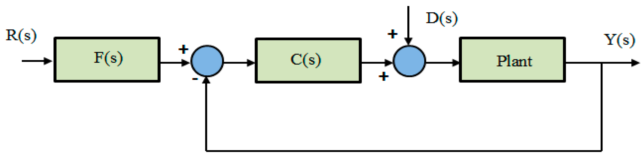
4.1. Two-Degree-of-Freedom PID Voltage Loop

In order to achieve the desired high performance of the voltage outer closed loop in terms of settling time, overshoot, disturbance rejection, and set point tracking, a two-degree-of-freedom PID controller is used [41]. This controller deals with the reference and the feedback signals separately. Also, 2DOFPID regulators are additionally effective for limiting the impact of reference signal variations regarding the control signal. The 2DOFPID controllers include specified set point weights for the proportional, integral, and derivative actions to guarantee that the influence of the disturbance is rapidly mitigated, while eliminating overshoot when controlling the desired value [42]. The main structure of the controller is depicted in Figure 6, which illustrates two distinct loops. R(s) and Y(s) are the two input signals of the controllers, which indicate the reference input and the output of the measured system, respectively. KP, KI, and KD represent the proportional, integral, and derivative parameters, while Br and Cr are set point weights related to proportional and derivative actions, and N is the coefficient of the filter associated with derivative action. The filter is used to avoid noise affected by derivative actions. The mathematical equation for 2DOFPID is given as [43]:
u = k p   ( B r R Y ) + k i / s ( R Y ) + ( k d s ) / ( N s + 1 ) ( C r ) Y )
A two-degree-of-freedom control scheme is presented in Figure 7. C(s) provides the one-degree-of-freedom regulator in this structure, D(s) represents the load disturbance, and F(s) functions as a preliminary filter on the reference input. The transfer functions of C(s) and F(s) in the two-degree-of-freedom PID controller are provided as:
F s = B r k p + C r k d s 2 + B r k p N + k i s + k i N k p + N k d s 2 + k p N + k i s + k i N
C s = k p + N k d s 2 + k p N + k i s + k i N s + N s

4.2. Super-Twisting Integral Sliding Controller Current Loop

The primary purpose of the current inner loop regulation is to guarantee that the actual measuring inductor current tracks the reference current created by the voltage outer loop. To ensure the robustness and effectiveness of the studied IBC system, a fast nonlinear higher-order super-twisting integral sliding mode controller is designed to regulate the inductor current loop. Therefore, its stability is not limited to the operating point. The principal benefits of STISM [44] involve (1) the robustness in the presence of resembled external perturbations as well as random changes in parameters; (2) that only having information regarding the sliding surface S is sufficient; (3) that it eliminates the chattering phenomena; and (4) the elimination of the reaching phase to improve the whole system response by using a integral sliding surface [45].
The current tracking error, IL, is given as:
e i = I L i I L r e f
where i = 1 to 3.
According to the concept of integral sliding mode control, the sliding surface is given as follows:
S i = e i + K 0 t e i d t
where K represents a positive control gain. It should be mentioned that the low gain values will result in a slow system convergence, which reduces the performance of the entire system, however, the very high values of K can imply very fast system convergence with significant perturbation and lead to system instability.
By using Equations (11), (17), and (18), the derivative of the proposed sliding surface can be given by Equation (18):
S ˙ i = 1 L ( V f c ( 1 u ) V b u s ) + K e i
The equivalent control law Ue can be obtained by equated the sliding surface derivative with zero, illustrated in Equation (20):
U e i = 1 V b u s ( V b u s V f c K L e i )
Based on the super twisting law given by Levant in [46], the control term comprises two laws; the first law, specified in (22), enables the sliding surface S i to converge towards zero, while the second law, presented in (23), permits achieving a smooth response by resulting in S ˙ i = 0.
U S T W = U 1 ( t ) + U 2 ( t )
where
U ˙ 1 = α   s i g n ( S )
U 2 = λ S 0.5   s i g n ( S )
By substituting (22) and (23) in Equation (21), the super twisting law is given as:
U S T W = λ S 0.5   s i g n ( S ) α   s i g n ( S )   d t
The global command law contains the sum of the equivalent control law and the super-twisting control term. Using Equations (20) and (24), the global command law can be written as (25).
U i = 1 V b u s ( V b u s V f c K L e i ) λ S 0.5   s i g n ( S ) α   s i g n ( S )   d t
The parameters of the super-twisting controller λ and α are positive to fulfill system convergence and must be determined as [46].
α > Φ M Γ M
λ > 4 · Φ · Γ M α + Φ M Γ m 3 ( α Φ M )
in which Γ M and Γ m represent the minimum and maximum limits of the uncertain function Γ, and Φ M is the highest limit of the perturbation Φ. These quantities are defined as positive terms and determined through the second derivative of the sliding surface:
S ¨ i = Φ x , t + Γ x , t · u ˙
where u ˙ represents the control derivative and the functions Γ and Φ are determined using the second derivative of the sliding surface which is obtained via (19) as
S ˙ i = 1 L ( V ˙ f c V ˙ b u s ) + K e ˙ i + 1 L u V ˙ b u s Φ + 1 L V b u s Γ u ˙
To prove the system stability, a positive adequate Lyapunov candidate function should be selected and its negative should be negative. Consider the Lyapunov function presented below:
V = 1 2 · S 2
Therefore, the derivation of the Lyapunov candidate function V is calculated as follows:
V = S · S ˙ = S 1 L ( V f c ( 1 u ) V b u s + K e i = S 1 L V f c 1 L V b u s + K e i + 1 L u V b u s = S 1 L V f c 1 L V b u s + K e i + 1 L 1 V b u s ( V b u s V f c K L e i ) V b u s + 1 L U S T W V b u s = S 1 L V f c 1 L V b u s + K e i + 1 L V b u s 1 L V f c K e i + 1 L U S T W V b u s = S 1 L U S T W V b u s = 1 L V b u s λ S 3 2   s i g n ( S ) 1 L S V b u s α   s i g n ( S )   d t
It can be observed that that the two parts of Equation (31) are negative, while λ and α are positive, and the derivation of Lyapunov candidate function is negative. Thus, the stability condition was effectively ensured.

4.3. Optimal Tuning of Controller Parameters

For the majority of control strategies, the selection of controller gain is not a simple task. The process of selecting these parameters to ensure the desired controller performance is defined as the tuning method. An optimization algorithm is a suitable solution for controller tuning parameters to select the optimal gains that guarantee a high performance of the system. In this paper, the atom search optimization algorithm (ASO) is employed to determine the best parameters of the proposed dual-loop control [47]. In the optimization process, the fitness/objective function is initially determined dependent on the desired performances. The objective function should be reduced as much as possible during the execution of the algorithm, and the minimum value of this function leads us to obtain the optimal gains of the controller. In general, numerous objective criterions are often mentioned in published research, such as the proposed functions of the integral of time-weighted absolute error (ITAE) which exhibits improved performances as compared with other objective criterions [48]. This function is designed to enhance the system robustness in the presence of load variations, uncertainties, and faulty operations. The fitness function Fit is given as:
F i t = C 1 0 t e 1 ( t ) t d t + C 2 0 t e 2 ( t ) t d t
where e 1 represents the error between the reference voltage and the output voltage, e 2 is the difference between the reference current and the measured inductor current, and C1 and C2 represent the weighting parameters.
Figure 8 illustrates the whole block architecture of the proposed ASO dual-loop 2DOFPID-STISM controller approach applied to the control three-phase IBC converter.

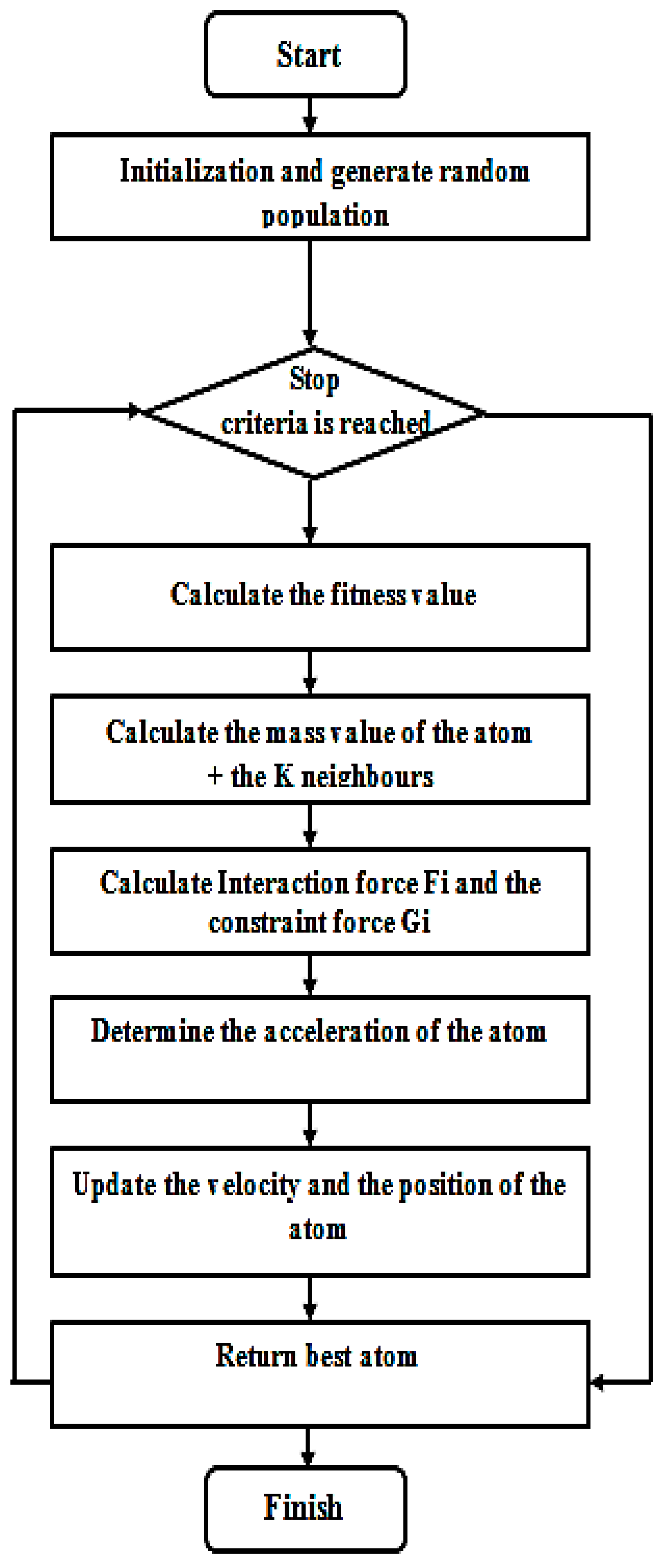
4.4. Atom Search Algorithm

The atom search algorithm, ASO, is a new, physics-inspired heuristic optimization algorithm proposed in [47] based on the principles of molecular dynamics. The approach imitates the atomic dynamics model in nature and the mechanics of atomic interactions from a microscopic viewpoint. The ASO algorithm formulation begins with the generation of a set of potential samples for optimization. After each iteration, the atoms’ locations and velocities are adjusted and the location of the best atom discovered is also updated [49]. Additionally, the atoms’ acceleration is determined via two factors: the interaction force from the L-J potential represented by a combination of attraction and repulsion from other atoms and the constraint force caused by the bond length potential, which is the weighted difference in position between each atom and the best atom. Finally, the algorithm updates the position and the velocity and returns the fitness value of the best atom, providing the optimum solution. The main step formulations of the ASO algorithm [50] are presented in Figure 9 and demonstrated as follows:
Step 1: Initialization and generation of random population.
Generate a random new population with a set of atoms x (solutions) and their velocity v, and set FitBest = Inf.
x i = x i 1 , x i 2 , . . . . . . . . . . . . . . . . . . . . . . , x i t h
v i = v i 1 , v i 2 , . . . . . . . . . . . . . . . . . . . . . . , v i t h
where i = [1, ..............., N]
Step 2: Calculate the fitness value.
The fitness function F i t i t is employed to find the optimal parameters to provide the best results.
Here, if F i t i t < F i t b e s t , then F i t b e s t = F i t i t and X B e s t = X i .
Step 3: Calculate the mass value of the atom.
The mass of the ith atom at the th iteration is calculated and linked to the fitness value of the atom function as
M i t = e F i t i t F i t B e s t t F i t w o r s t t F i t B e s t t
m i = M i t j = 1 N M j t
where m i represents the mass of the ith atom at the tth iteration.
Here, fitworst(t) and Fitbest(t) represent the highest and the lowest fitness values at the th iteration.
f i t b e s t t = m i n i 1,2 , , N F i t i t f i t w o r s t t = m a x i 1,2 , , N F i t i t
Step 4: Calculate the K neighbors for each atom.
In order to improve the exploration process in the ASO algorithm at the primary iterations, each atom must react with numerous atoms’ k neighbors who possess better fitness scores, and to ameliorate the algorithm exploitation stage at the final iterations, every atom needs to react with atoms providing slightly better fitness scores. The K neighbors can be calculated as
K t = N N 2 × t T
where t and T represent the current and highest numbers of iteration, respectively, and N is the total number of the atom population.
Step 5: Interaction force Fi and the constraint force Gi calculation.
The total force is calculated by the sum of parts with random weights operating on the ith atom and the other atoms, which is denoted by the following:
F i d t = j K b e s t r a n d j F i j d t , r a n d j 0,1
The constraint force G can be computed using Equation (40)
G i d t = λ t θ i d t = 2 λ t ( x i d t x b e s t d t
where θ i t is the geometric constraint related to the ith atom and given by
θ i t = x i t x b e s t t 2 b i , b e s t 2
where b i , b e s t refers to the length of the bond between the tth atom and the best atom.
λ(t) represents the Lagrangian factor and is written as
λ t = β e 20 t T
Step 6: Calculate the acceleration.
The acceleration a of the ith atom at time t is defined in the following way:
a i d t = F i d t m i d t + G i d t m i d t
Step 7: Update the velocity and the position process.
The position and velocity of the ith atom at the (t + 1)th iteration can be represented through the following equations:
x i d t + 1 = x i d t + v i d t + 1
v i d t + 1 = r a n d i d v i d t + a i d t

5. Performance Validation and Simulation Results

The effectiveness and the robustness of the proposed optimized controller are evaluated using the MATLAB/Simulink environment. The main goal of the controller is to ensure that the inductor current and output voltage pursue its reference perfectly, even in failure operations affected by one or two phases of the controlled IBC converter. The proposed dual-loop 2DOFPID- STISM-controller-based ASO algorithm is compared with two other optimization approaches that have been recently reported in the literature. Indeed, the proposed controller is compared with the dual-loop PID controller with the same ASO optimization method to ensure a fair comparison. The simulation parameters for the three-phase IBC converter are listed in Table 1.

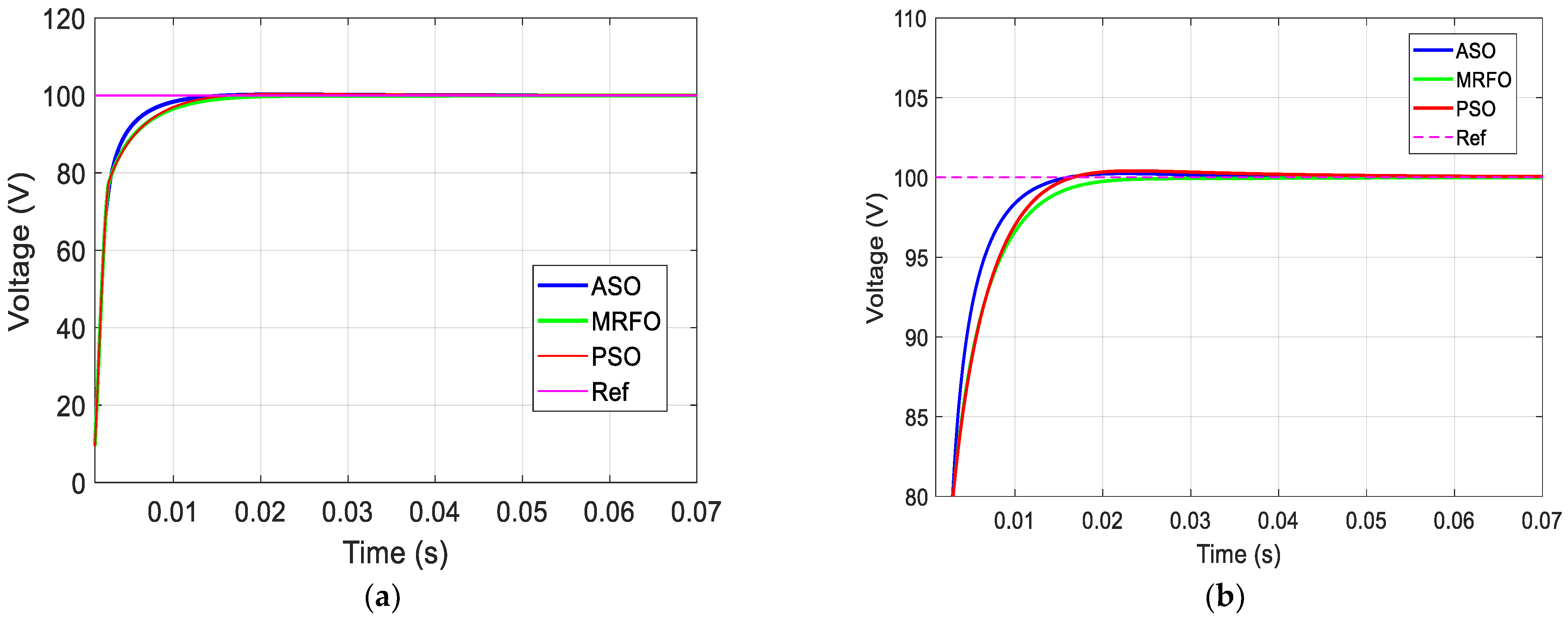
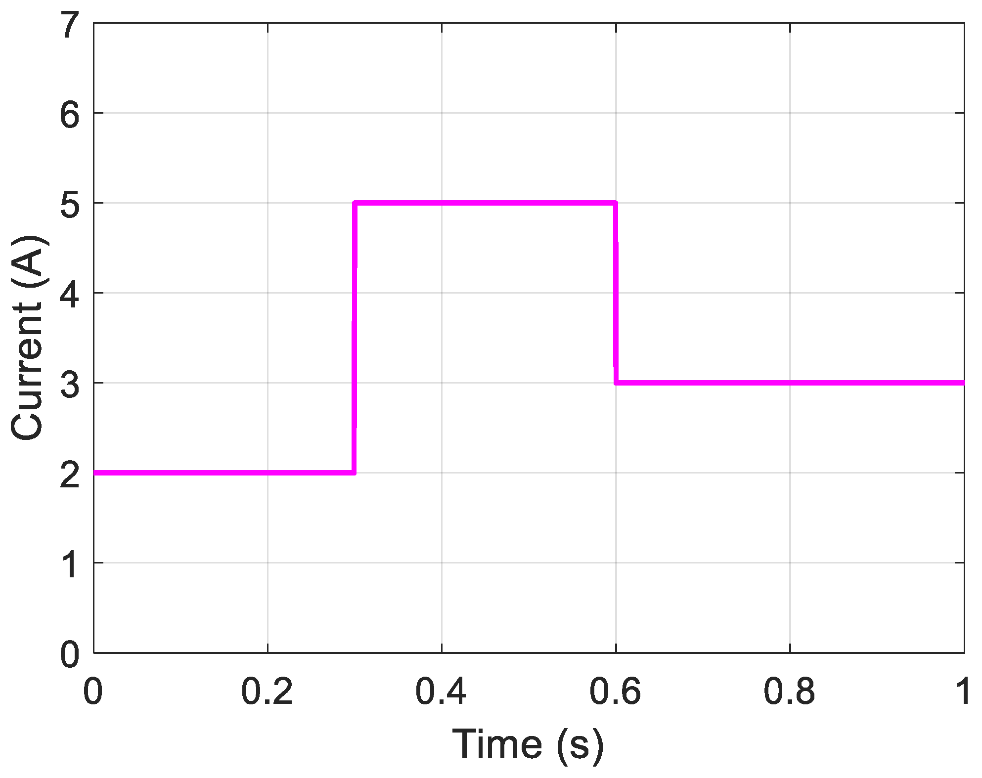
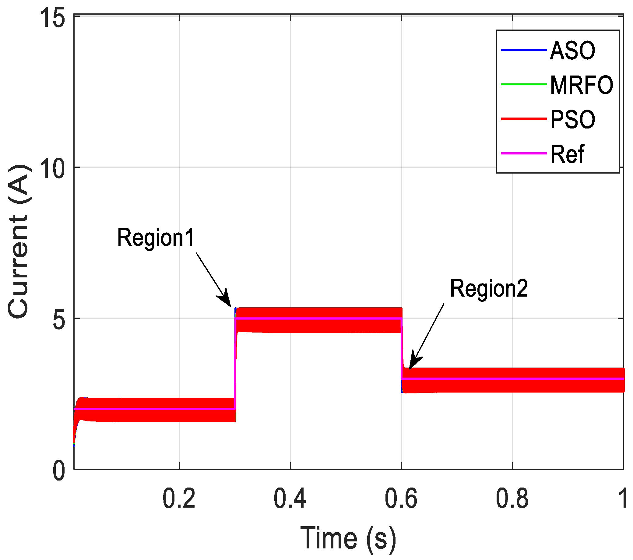
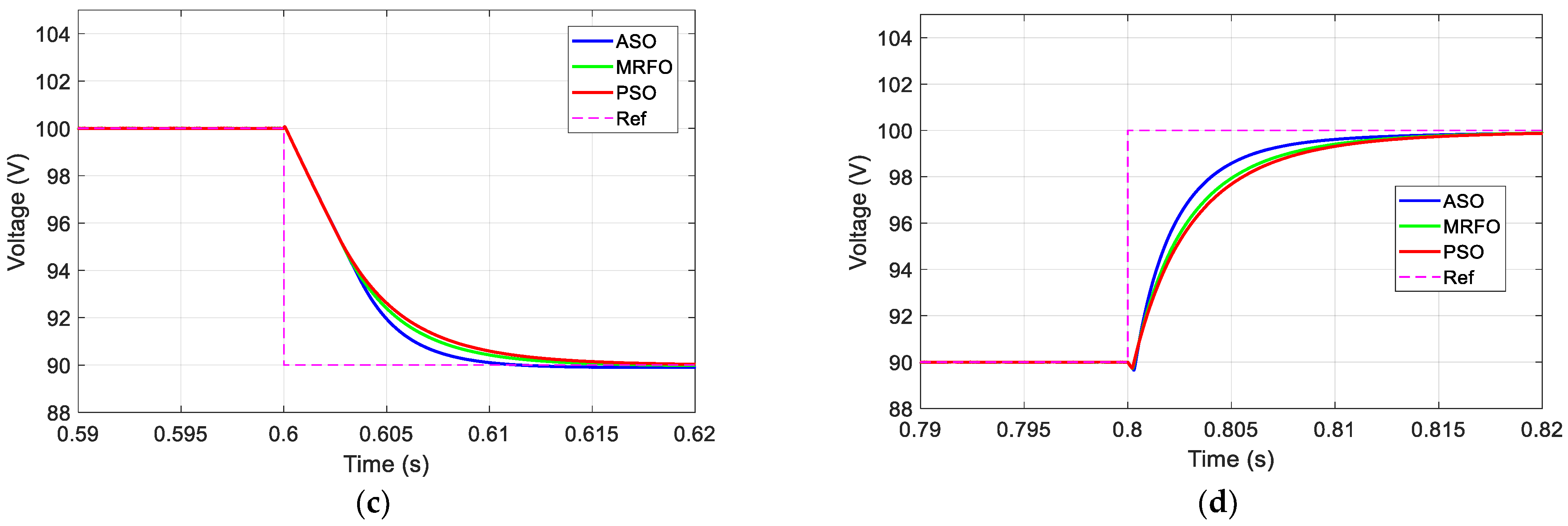
5.1. Examination of the Proposed Controller Compared with Other Optimization Techniques

The proposed ASO-tuned 2DOFPID- STISM controller is compared with two different algorithms presented in the literature with the same parameters for the converter (manta ray foraging algorithm, MRFO [51] and particle swarm approach [52,53]). Various simulation tests are performed to prove the effectiveness of the proposed controller. The main results are presented in the following subsections. Figure 10 depicts the convergence curves of the three tuning methods. The convergence curves indicate that the ASO presents the smallest objective function (fit = 0.0042) and quickly converges compared with the other algorithms (after seven iterations).
The obtained optimal parameters of the controller using the three optimization algorithms after 50 iterations are reported in Table 2.
The transient and steady responses of the IBC converter for the ASO, MRFO, and PSO tuning methods for the proposed controllers are presented in Figure 11.
In Table 3, the performance analysis of the three tuning methods applied to the proposed controller is illustrated in terms of the performance criteria.
By analyzing Figure 11 and Table 3, one can observe that the ASO tuning method for the proposed 2DOFPID-STISM controller exhibits better performance criteria with faster response compared with the MRFO and PSO tuning algorithms.
To examine the proposed controller response tuned using the ASO, MRFO, and PSO optimization algorithms under various operating modes, three robustness tests are performed. Firstly, the proposed current loop performance against a reference change was evaluated. The value of the reference current was adjusted from 2A to 5A and from 2A to 5A (Figure 12) to analyze the response of inductive currents.
Figure 13 and Figure 14 show the tracking behavior of the inductor current after reference variation. A fast analysis of the comparison proves that the ASO-tuned inner current loop demonstrates a higher performance than the other algorithms with the lowest ITAE = 0.0077 (as depicted in Table 3) and fastest settling time, which confirms the significant effectiveness of the proposed ASO-STISM current loop.
In the second robustness test, the load distribution rejection ability of the examined controllers is evaluated. For this reason, a twice-loaded current variation is carried out: first, the load is decreased from 2A to 0.5 A at t = 0.2s and 0.4s and then, the second load is increased from 2A to 4 A at t = 0.6s and 0.8s, respectively, as presented in Figure 15.
Figure 16 illustrates the output voltage waveform after the series of load current variations and Figure 17 shows the details of the tracking behavior of the output voltage after each variation. Table 4 represents two performance criteria evaluating the compared tuning method in each region of load variation. It can be observed from the table analysis and the two figures that the ASO-tuned proposed controller always provided the lowest level of overshoot and the fastest response time compared with the other algorithms.
The third robustness test involves a variable reference voltage; in this test, a variable reference voltage is adjusted from 100 to 110 v and from 100 to 90 v via a defined profile with a constant load, which is displayed in Figure 18.
Figure 19 shows a detailed image of the output voltage simulation response with a variable reference voltage in each region of variation. As can be observed from these figures, the ASO tuning method applied to the proposed controller provides a higher performance in terms of settling time (0.01 s) and without overshoot compared with the MRFO and PSO tuning approaches.

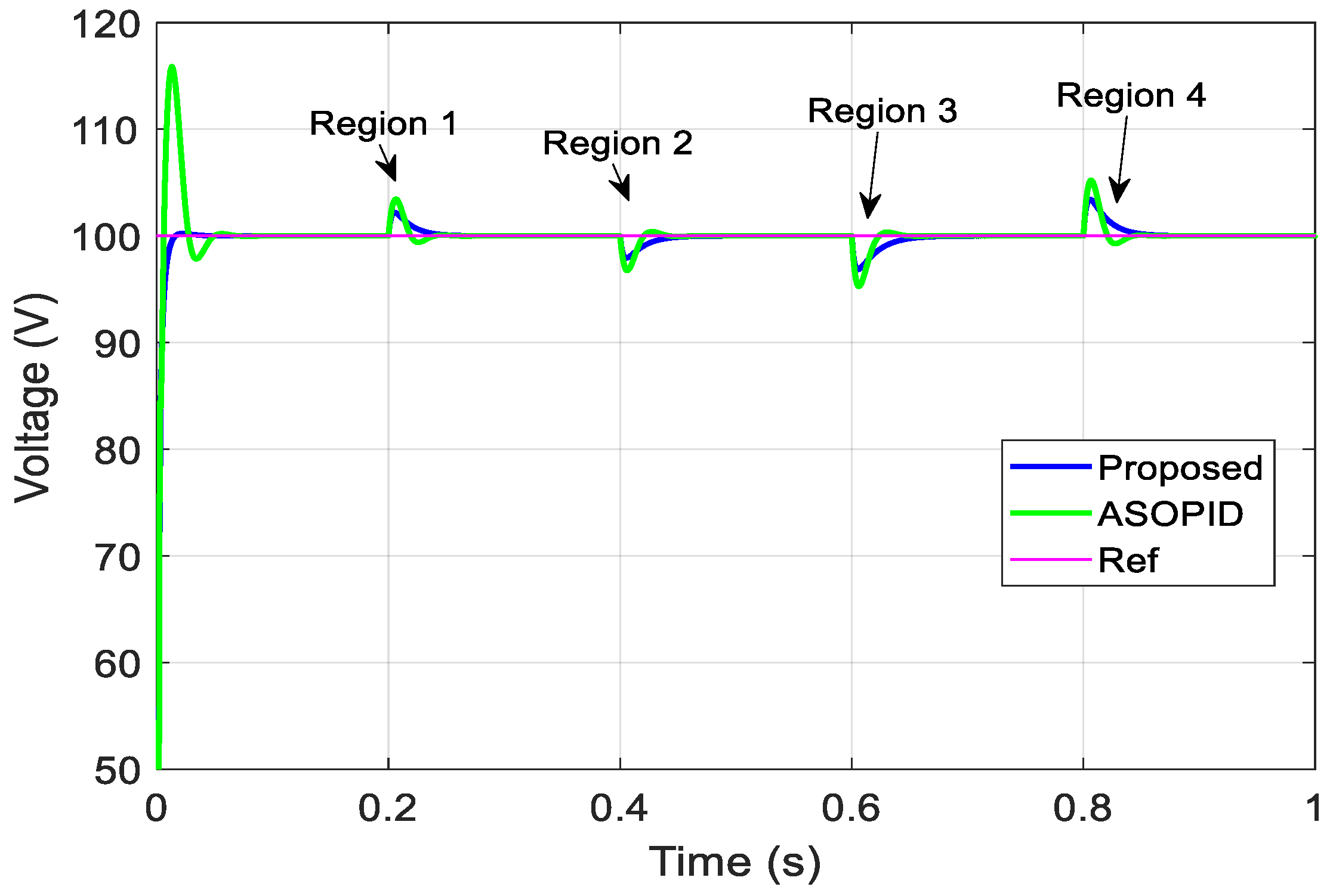
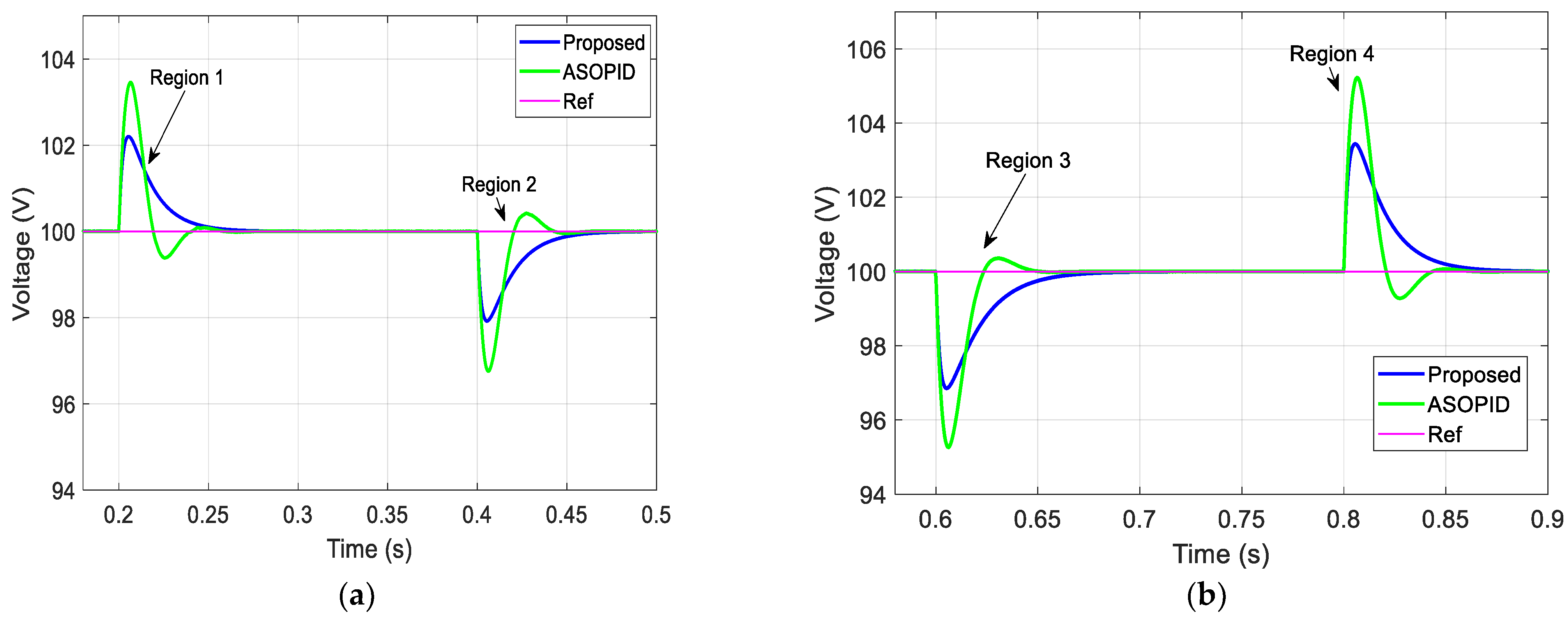
5.2. Examination of the ASO-Tuned Proposed Controller Compared with the ASO-PID Controller

For closer examination, the proposed ASO-tuned 2DOFPID- STISM controller is compared with the PID dual-loop controller tuned by the ASO algorithm; for fair comparison between the two controllers, the comparison is made with the same parameter, listed in Table 1, and the same examination of the robustness test as in the previous section. The advantages of the controller tuned by the ASO algorithm are presented in Table 5.
Figure 20 depicts the transient and steady output voltage waveforms of the IBC converter controlled with the two controllers. Through a brief examination of the comparison presented in Table 6, the effectiveness of the ASO-based proposed controller is confirmed, with improved performance compared against the ASO-PID technique; additionally, the rates of settling time and overshoot reinforce the notable contribution of the proposed control structure.
Figure 21 and Figure 22 show the tracking response comparison of the two controllers of the current loop after the variation of the reference profile presented in the previous section. The better performance of the suggested controller can be seen from the fact that the response utilizing the ASO-PID current loop exhibits an overshoot of 1A, whereas the response using the ASO-tuned 2DOFPID-STISM controller is without overshoot.
Figure 23 and Figure 24 illustrate the load variation test performed for the ASO-PID controller and the proposed controller. The output voltage response comparison of the two controllers is presented in each region of variation. From the results, the proposed controller preserves a steady output voltage with lower overshoot and undershoot in case of load variation compared with the ASO-PID dual-loop.
Figure 25 exhibits the output voltage simulation results under an adjustable voltage reference. As a result, the suggested controller provides an improved settling time without any overshoot in each region of the step voltage reference, whereas the ASO-PID controller provides a low settling time with a significant overshoot. It is noticeable from the previous simulation tests that the system’s dynamic performance is enhanced using the proposed controller tuned by the ASO algorithm.

5.3. Robustness Examination of the ASO-Tuned Proposed Controller against Uncertainty

To test the robustness of the proposed ASO-tuned 2DOFPID-STISM controller against uncertainty, two varieties of uncertainty tests are taken into account.
The first uncertainty test is created by a variation in a converter component, such as the output capacitor, which is produced by the degradation of the component. For that reason, the capacitor value was changed from 1100 μF to 400 μF during the simulation test. Figure 26 represents the output voltage of the converter under capacitor variation in 0.2 s. By analyzing this figure, one can see that the proposed controller ensures an improved fixed output voltage in the presence of degradation or deviations of converter components, which improves the robustness of the controller.
The second uncertainty test is introduced through variations in fuel cell operation, such as sudden input voltage reductions. Figure 27 depicts the output voltage waveform of the IBC converter piloted under the proposed controller after a sudden fuel cell input voltage change from 37 v to 30 v at t = 0.2 s.
It is noticeable that the proposed approach clearly exhibits a high output performance under variations in fuel cell operation with negligible overshoot and a very low settling time.

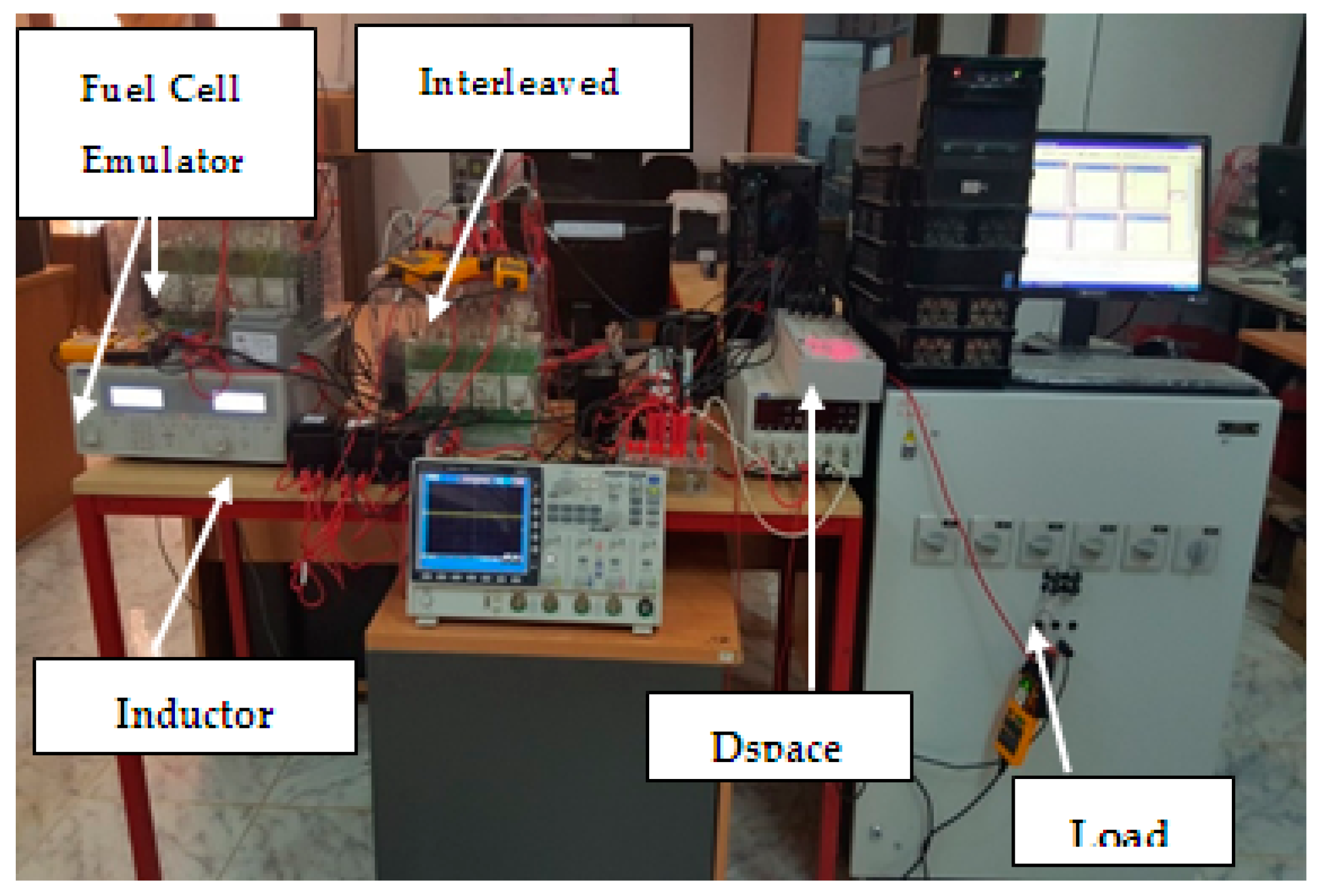
6. Experimental Validation of the Proposed Controller

In order to evaluate the ASO dual-loop 2DOFPID-STISM control approach proposed in this study in real-time validation, an experimental test prototype (1.2 kw) is built in the Energy Systems Modelling Laboratory LMSE Laboratory. Figure 28 displays a representation of the real-time test bench for the three-phase IBC converter coupled with adjustable resistive load. A PEMFC-realized emulator is designed to mimic the electrical characteristic of an actual Ballard PEMFC (1.2 KW), which comprises a Buck converter alimented with a DC programmable source controlled via voltage loop to emulate the I–V curve of a real PEMFC. The system architecture of the FC emulator is depicted in Figure 29. The three-phase IBC converter is built with IGBT SEMIKRON SKM50GB123 modules at 10 kHz switched frequency. The designed control algorithms are implemented via DSPACE-1104 R&D Controller Board and MATLAB-Simulink RTW package. The adapting of control signal levels between the DSPACE-1104 board and power switch driver are carried out by means of a developed adaptation card. Measurements are performed through LA25NP and LV25P hall current and voltage sensors. Table 7 represents the experimental parameters of the test bench
To validate in real time the implementation of the proposed controller with the same operating modes as presented in the simulation section, firstly, the inner current loop of the controller was examined, and the reference current was changed to evaluate the behavior of each phase current.
Figure 30 and Figure 31 present the experimental results of the inductor current waveform under step load variation. The experimental results confirm the high tracking performance of the inner loop in terms of settling time and overshoot.
Figure 32 shows the input current of the PEMFC emulator; the present results illustrate that the designed current loop provides a robust capability for limiting PEMFC current overshoot, which allows for protection and enhances the average lifespan of the FC.
Figure 33, Figure 34, Figure 35, Figure 36 and Figure 37 present the evolution of the system, including for load current disturbances, varied at t = 0.5 s, t = 1.9 s, t = 4 s, and t = 5.2 s. One can see that in the controller, in order to maintain steady output voltage, the inductor currents of each leg track the reference generated perfectly via the outer voltage loop with negligible overshoots and improved response time.
Figure 38 depicts a practical tracking test under a variable reference voltage. The desired reference voltage variations are carried out at two voltage levels. This result demonstrates a high tracking efficiency of the designed controller which allows it to maintain the output voltage at a stable level to meet the load requirements.
To prove the high efficiency and robustness of the proposed optimal dual-loop control under failure mode, two open-circuit faults (OCF) have been created in the power transistor device. The first OCF occurs at 0.6s and the second one at t = 2.7 s. However, Figure 39, Figure 40 and Figure 41 demonstrate the controller response and the waveform of inductor currents, output voltage, and PEMFC simulator currents and voltages under failure mode.
By analyzing the experimental results depicted in Figure 39 and Figure 40, one can observe that the proposed optimal controller ensures a stable output voltage and inhibits overshoot within a short time, even in failure mode. The first OCF has been created during phase 2 and the second during phase 3 of the IBC converter.
Figure 41 shows the PEMFC emulator current voltage in the presence of a failure condition; the introduced results prove that the proposed controller preserves PEMFC requirements (without unacceptable overshoot or ripple). From these results, the proposed controller can compensate for the impact of failure operations with high practical performance.

7. Real-Time Hardware Implementation Challenges

Real-time validation of the simulation results of the proposed controller applied to the three-phase IBC converter presented a number of challenges in this study. In order to provide valuable guidance for researchers and engineers seeking to apply similar control strategies in practical systems, this section demonstrates these issues and proposes some solutions used to solve the presented challenges.
  • Equal current sharing and synchronous phase control of the interleaved converters: Ensuring equitable current sharing and phase control of the interleaved converters was a crucial issue. A dedicated effort was made to optimize the control sequence, which minimizes ripple effects and achieves efficient power transfer.
  • Precision of the sensor and signal filtering: The analogue sensors used in the prototype may produce noisy data. This can degrade the quality of the feedback signal and destabilize the control loop. To address this issue, a numeric low-pass filter is added to the measured voltages and currents to smooth the data and ensure a reliable measured signal.
  • Handling of the computational overloads on DSpace 1104: Complex control algorithms and simultaneous tasks may lead to reaching the DS1104’s computational limits, which can lead to possible overloads. For that reason, the Simulink control algorithms must be optimized, and nonessential tasks are offloaded to reduce computational strain on the DS1104.

8. Conclusions

This work presents an improved optimal dual-loop control applied to a three-phase interleaved BOOST DC/DC converter for fuel cell applications. The proposed controller is composed of a dual-loop control structure, which involves a voltage loop based on a two-degree-of-freedom PID controller and a fast current loop design based on a super-twisting integral sliding mode (STISM) algorithm. This controller is applied to achieve regulated output voltage and equal current distribution across all phases of the IBC converter in the presence of load variations and failure operations. The proposed 2DOF-PID-STISM controller parameter selection is designed and successfully optimized using the atom search optimization algorithm. The optimization design process of the suggested controller has been described in depth. For comparison, the proposed control has been examined and its performance compared with two other optimization algorithms (PSO and MRFO) as well as with a dual-loop ASO-based PID controller, taking into account different operation modes. The simulation results demonstrate the superiority and robustness of the proposed control scheme in terms of overshoot and settling time in transient and steady response.
Finally, the controller has been verified and implemented in real time using an experimental test bench, proving a high performance under various operating modes.

Author Contributions

Conceptualization, R.S. and M.Y.H.; methodology, R.S., M.Y.H. and O.S.; software, R.S., M.Y.H. and O.S.; validation, R.S., M.Y.H. and O.S.; formal analysis, R.S., M.Y.H., K.L. and O.S. investigation, R.S.; resources, R.S.; data curation, R.S.; writing—original draft preparation, R.S.; writing—review and editing, R.S., M.Y.H., K.L. and A.J.M.C.; visualization, R.S., M.Y.H. and K.L.; supervision, A.J.M.C.; project administration, A.J.M.C.; funding acquisition, A.J.M.C. All authors have read and agreed to the published version of the manuscript.

Funding

This work was supported by National Funds through the FCT-Portuguese Foundation for Science and Technology, under Projects UIDB/04131/2020, UIDP/04131/2020.

Conflicts of Interest

The authors declare no conflict of interest.

References

  1. Olabi, A.G.; Wilberforce, T.; Abdelkareem, M.A. Fuel cell application in the automotive industry and future perspective. Energy 2021, 214, 118955. [Google Scholar] [CrossRef]
  2. Ayad, M.; Becherif, M.; Henni, A. Vehicle hybridization with fuel cell, supercapacitors and batteries by sliding mode control. Renew. Energy 2011, 36, 2627–2634. [Google Scholar] [CrossRef]
  3. Wang, Y.; Yue, L.; Wang, S. New design of a cathode flow-field with a sub-channel to improve the polymer electrolyte membrane fuel cell performance. J. Power Sources 2017, 344, 32–38. [Google Scholar] [CrossRef]
  4. Hu, K.; Zhao, P.; Wang, S.; Wang, Y. Three-dimensional multiphase simulation of a partially narrowed flow field configuration for a high-performance polymer electrolyte membrane fuel cell. Appl. Therm. Eng. 2023, 223, 119986. [Google Scholar] [CrossRef]
  5. Wang, Y.; Xu, H.; Wang, X.; Gao, Y.; Su, X.; Qin, Y.; Xing, L. Multi-sub-inlets at cathode flow-field plate for current density homogenization and enhancement of PEM fuel cells in low relative humidity. Energy Convers. Manag. 2022, 252, 115069. [Google Scholar] [CrossRef]
  6. Alavi, O.; Rajabloo, T.; De Ceuninck, W.; Daenen, M. Non-isolated DC-DC converters in fuel cell applications: Thermal analysis and reliability comparison. Appl. Sci. 2022, 12, 5026. [Google Scholar] [CrossRef]
  7. Guilbert, D.; N’Diaye, A.; Gaillard, A.; Djerdir, A. Fuel cell systems reliability and availability enhancement by developing a fast and efficient power switch open-circuit fault detection algorithm in interleaved DC/DC boost converter topologies. Int. J. Hydrogen Energy 2016, 41, 15505–15517. [Google Scholar] [CrossRef]
  8. Thounthong, P.; Davat, B.; Rael, S.; Sethakul, P. Fuel cell high-power applications. IEEE Ind. Electron. Mag. 2009, 3, 32–46. [Google Scholar]
  9. Liu, C.; Lai, J.-S. Low frequency current ripple reduction technique with active control in a fuel cell power system with inverter load. IEEE Trans. Power Electron. 2007, 22, 1429–1436. [Google Scholar] [CrossRef]
  10. Zhan, Y.; Guo, Y.; Zhu, J.; Liang, B.; Yang, B. Comprehensive influences measurement and analysis of power converter low frequency current ripple on PEM fuel cell. Int. J. Hydrogen Energy 2019, 44, 31352–31359. [Google Scholar] [CrossRef]
  11. Kabalo, M.; Paire, D.; Blunier, B.; Bouquain, D.; Godoy Simões, M.; Miraoui, A. Experimental evaluation of four-phase floating interleaved boost converter design and control for fuel cell applications. IET Power Electron. 2013, 6, 215–226. [Google Scholar] [CrossRef]
  12. Wang, H.; Gaillard, A.; Hissel, D. A review of DC/DC converter-based electrochemical impedance spectroscopy for fuel cell electric vehicles. Renew. Energy 2019, 141, 124–138. [Google Scholar] [CrossRef]
  13. Kolli, A.; Gaillard, A.; De Bernardinis, A.; Bethoux, O.; Hissel, D.; Khatir, Z. A review on DC/DC converter architectures for power fuel cell applications. Energy Convers. Manag. 2015, 105, 716–730. [Google Scholar] [CrossRef]
  14. Thounthong, P.; Mungporn, P.; Guilbert, D.; Takorabet, N.; Pierfederici, S.; Nahid-Mobarakeh, B.; Hu, Y.; Bizon, N.; Huangfu, Y.; Kumam, P. Design and control of multiphase interleaved boost converters-based on differential flatness theory for PEM fuel cell multi-stack applications. Int. J. Electr. Power Energy Syst. 2021, 124, 106346. [Google Scholar] [CrossRef]
  15. Arunkumari, T.; Indragandhi, V. An overview of high voltage conversion ratio DC-DC converter configurations used in DC micro-grid architectures. Renew. Sustain. Energy Rev. 2017, 77, 670–687. [Google Scholar] [CrossRef]
  16. Farhani, S.; N’Diaye, A.; Djerdir, A.; Bacha, F. Design and practical study of three phase interleaved boost converter for fuel cell electric vehicle. J. Power Sources 2020, 479, 228815. [Google Scholar] [CrossRef]
  17. Yao, Y.; Gao, S.; Wang, Y.; Liu, X.; Zhang, X.; Xu, D. Design and optimization of an electric vehicle wireless charging system using interleaved boost converter and flat solenoid coupler. IEEE Trans. Power Electron. 2020, 36, 3894–3908. [Google Scholar] [CrossRef]
  18. Hao, X.; Salhi, I.; Laghrouche, S.; Ait-Amirat, Y.; Djerdir, A. Backstepping supertwisting control of four-phase interleaved boost converter for PEM fuel cell. IEEE Trans. Power Electron. 2022, 37, 7858–7870. [Google Scholar] [CrossRef]
  19. Somkun, S.; Sirisamphanwong, C.; Sukchai, S. A DSP-based interleaved boost DC–DC converter for fuel cell applications. Int. J. Hydrogen Energy 2015, 40, 6391–6404. [Google Scholar] [CrossRef]
  20. Arango, E.; Ramos-Paja, C.; Calvente, J.; Giral, R.; Romero, A.; Martinez-Salamero, L. Fuel cell power output using a LQR controlled AIDB converter. In Proceedings of the 2007 International Conference on Clean Electrical Power, Capri, Italy, 21–23 May 2007; pp. 492–499. [Google Scholar]
  21. Mungporn, P.; Thounthong, P.; Yodwong, B.; Ekkaravarodome, C.; Bilsalam, A.; Pierfederici, S.; Guilbert, D.; Nahid-Mobarakeh, B.; Bizon, N.; Shah, Z. Modeling and control of multiphase interleaved fuel-cell boost converter based on Hamiltonian control theory for transportation applications. IEEE Trans. Transp. Electrif. 2020, 6, 519–529. [Google Scholar] [CrossRef]
  22. Huangfu, Y.; Zhuo, S.; Chen, F.; Pang, S.; Zhao, D.; Gao, F. Robust voltage control of floating interleaved boost converter for fuel cell systems. IEEE Trans. Ind. Appl. 2017, 54, 665–674. [Google Scholar] [CrossRef]
  23. Thammasiriroj, W.; Chunkag, V.; Phattanasak, M.; Pierfederici, S.; Davat, B.; Thounthong, P. Nonlinear single-loop control of the parallel converters for a fuel cell power source used in DC grid applications. Int. J. Electr. Power Energy Syst. 2015, 65, 41–48. [Google Scholar] [CrossRef]
  24. Long, R.; Quan, S.; Zhang, L.; Chen, Q.; Zeng, C.; Ma, L. Current sharing in parallel fuel cell generation system based on model predictive control. Int. J. Hydrogen Energy 2015, 40, 11587–11594. [Google Scholar] [CrossRef]
  25. Zhuo, S.; Xu, L.; Huangfu, Y.; Gaillard, A.; Paire, D.; Gao, F. Robust adaptive control of interleaved boost converter for fuel cell application. IEEE Trans. Ind. Appl. 2021, 57, 6603–6610. [Google Scholar] [CrossRef]
  26. Salhi, B.; El Fadil, H.; Ahmed Ali, T.; Magarotto, E.; Giri, F. Adaptive output feedback control of interleaved parallel boost converters associated with fuel cell. Electr. Power Compon. Syst. 2015, 43, 1141–1158. [Google Scholar] [CrossRef]
  27. Belhaj, F.; El Idrissi, Z.; El Fadil, H.; Lassioui, A.; Gaouzi, K.; Koundi, M.; Giri, F.; El Fakir, C. Output-feedback control of interleaved Buck-Boost DC-DC power converter with continuous input current for fuel cell energy sources. In Proceedings of the 2022 IEEE 3rd International Conference on Electronics, Control, Optimization and Computer Science (ICECOCS), Fez, Morocco, 1–2 December 2022; pp. 1–6. [Google Scholar]
  28. Mungporn, P.; Yodwong, B.; Thounthong, P.; Nahid-Mobarakeh, B.; Takorabet, N.; Guilbert, D.; Kumam, P.; Bizon, N.; Kaewprapha, C. Model-free control of multiphase interleaved boost converter for fuel cell/reformer power generation. In Proceedings of the 2019 Research, Invention, and Innovation Congress (RI2C), Bangkok, Thailand, 11–13 December 2019; pp. 1–6. [Google Scholar]
  29. Araki, M.; Taguchi, H. Two-degree-of-freedom PID controllers. Int. J. Control Autom. Syst. 2003, 1, 401–411. [Google Scholar]
  30. Pan, Z.; Dong, F.; Zhao, J.; Wang, L.; Wang, H.; Feng, Y. Combined resonant controller and two-degree-of-freedom PID controller for PMSLM current harmonics suppression. IEEE Trans. Ind. Electron. 2018, 65, 7558–7568. [Google Scholar] [CrossRef]
  31. Jain, M.; Rani, A.; Pachauri, N.; Singh, V.; Mittal, A.P. Design of fractional order 2-DOF PI controller for real-time control of heat flow experiment. Eng. Sci. Technol. Int. J. 2019, 22, 215–228. [Google Scholar] [CrossRef]
  32. Hussain, I.; Das, D.C.; Latif, A.; Sinha, N.; Hussain, S.S.; Ustun, T.S. Active power control of autonomous hybrid power system using two degree of freedom PID controller. Energy Rep. 2022, 8, 973–981. [Google Scholar] [CrossRef]
  33. Mandala, I.I.; Nazaruddin, Y.Y. Optimization of two degree of freedom PID controller for quadrotor with stochastic fractal search algorithm. In Proceedings of the 2019 IEEE Conference on Control Technology and Applications (CCTA), Hong Kong, China, 19–21 August 2019; pp. 1062–1067. [Google Scholar]
  34. Karanam, A.N.; Shaw, B. A new two-degree of freedom combined PID controller for automatic generation control of a wind integrated interconnected power system. Prot. Control Mod. Power Syst. 2022, 7, 20. [Google Scholar] [CrossRef]
  35. Labbadi, M.; Cherkaoui, M. Novel robust super twisting integral sliding mode controller for a quadrotor under external disturbances. Int. J. Dyn. Control 2020, 8, 805–815. [Google Scholar] [CrossRef]
  36. Dali, A.; Abdelmalek, S.; Bakdi, A.; Bettayeb, M. A novel effective nonlinear state observer based robust nonlinear sliding mode controller for a 6 kW Proton Exchange Membrane Fuel Cell voltage regulation. Sustain. Energy Technol. Assess. 2021, 44, 100996. [Google Scholar] [CrossRef]
  37. Banerjee, S.; Ghosh, A.; Rana, N. An improved interleaved boost converter with PSO-based optimal type-III controller. IEEE J. Emerg. Sel. Top. Power Electron. 2016, 5, 323–337. [Google Scholar] [CrossRef]
  38. Guilbert, D.; Gaillard, A.; N’Diaye, A.; Djerdir, A. Energy efficiency and fault tolerance comparison of DC/DC converters topologies for fuel cell electric vehicles. In Proceedings of the 2013 IEEE Transportation Electrification Conference and Expo (ITEC), Detroit, MI, USA, 16–19 June 2013; pp. 1–7. [Google Scholar]
  39. Amphlett, J.C.; Baumert, R.M.; Mann, R.F.; Peppley, B.A.; Roberge, P.R.; Harris, T.J. Performance modeling of the Ballard Mark IV solid polymer electrolyte fuel cell: I. Mechanistic model development. J. Electrochem. Soc. 1995, 142, 1. [Google Scholar] [CrossRef]
  40. Mann, R.F.; Amphlett, J.C.; Hooper, M.A.; Jensen, H.M.; Peppley, B.A.; Roberge, P.R. Development and application of a generalised steady-state electrochemical model for a PEM fuel cell. J. Power Sources 2000, 86, 173–180. [Google Scholar] [CrossRef]
  41. Taguchi, H.; Araki, M. Two-degree-of-freedom PID controllers—Their functions and optimal tuning. IFAC Proc. Vol. 2000, 33, 91–96. [Google Scholar] [CrossRef]
  42. Guras, R.; Strambersky, R.; Mahdal, M. The PID and 2DOF control of the integral system-influence of the 2DOF parameters and practical implementation. Meas. Control 2022, 55, 94–101. [Google Scholar] [CrossRef]
  43. Gupta, N.K.; Kar, M.K.; Singh, A.K. Design of a 2-DOF-PID controller using an improved sine–cosine algorithm for load frequency control of a three-area system with nonlinearities. Prot. Control Mod. Power Syst. 2022, 7, 33. [Google Scholar] [CrossRef]
  44. Sami, I.; Ullah, S.; Basit, A.; Ullah, N.; Ro, J.-S. Integral super twisting sliding mode based sensorless predictive torque control of induction motor. IEEE Access 2020, 8, 186740–186755. [Google Scholar] [CrossRef]
  45. Utkin, V.; Shi, J. Integral sliding mode in systems operating under uncertainty conditions. In Proceedings of the 35th IEEE Conference on Decision and Control, Kobe, Japan, 13 December 1996; pp. 4591–4596. [Google Scholar]
  46. Levant, A. Higher-order sliding modes, differentiation and output-feedback control. Int. J. Control 2003, 76, 924–941. [Google Scholar] [CrossRef]
  47. Zhao, W.; Wang, L.; Zhang, Z. Atom search optimization and its application to solve a hydrogeologic parameter estimation problem. Knowl.-Based Syst. 2019, 163, 283–304. [Google Scholar] [CrossRef]
  48. Sahu, R.K.; Panda, S.; Rout, U.K. DE optimized parallel 2-DOF PID controller for load frequency control of power system with governor dead-band nonlinearity. Int. J. Electr. Power Energy Syst. 2013, 49, 19–33. [Google Scholar] [CrossRef]
  49. Zhao, W.; Shi, T.; Wang, L.; Cao, Q.; Zhang, H. An adaptive hybrid atom search optimization with particle swarm optimization and its application to optimal no-load PID design of hydro-turbine governor. J. Comput. Des. Eng. 2021, 8, 1204–1233. [Google Scholar] [CrossRef]
  50. Reddy, C.R.; Goud, B.S.; Aymen, F.; Rao, G.S.; Bortoni, E.C. Power quality improvement in HRES grid connected system with FOPID based atom search optimization technique. Energies 2021, 14, 5812. [Google Scholar] [CrossRef]
  51. Zhao, W.; Zhang, Z.; Wang, L. Manta ray foraging optimization: An effective bio-inspired optimizer for engineering applications. Eng. Appl. Artif. Intell. 2020, 87, 103300. [Google Scholar] [CrossRef]
  52. Eberhart, R.; Kennedy, J. A new optimizer using particle swarm theory. In Proceedings of the MHS’95. Proceedings of the Sixth International Symposium on Micro Machine and Human Science, Nagoya, Japan, 4–6 October 1995; pp. 39–43. [Google Scholar]
  53. Ghamari, S.M.; Narm, H.G.; Mollaee, H. Fractional-order fuzzy PID controller design on buck converter with antlion optimization algorithm. IET Control Theory Appl. 2022, 16, 340–352. [Google Scholar] [CrossRef]
Figure 1. Three-phase IBC converter.
Electronics 12 04113 g001
Figure 2. The impact of duty cycle on input ripples for different interleaved phases.
Electronics 12 04113 g002
Figure 3. Efficiency of IBC converter.
Electronics 12 04113 g003
Figure 4. Real characteristic curve compared with simulation model.
Electronics 12 04113 g004
Figure 5. Proposed control scheme.
Electronics 12 04113 g005
Figure 6. Main structure of the controller.
Electronics 12 04113 g006
Figure 7. Two-degree-of-freedom control scheme.
Electronics 12 04113 g007
Figure 8. Three-phase IBC converter with ASO dual-loop 2DOFPID-STISM controller.
Electronics 12 04113 g008
Figure 9. Flow chart of ASO optimization algorithm.
Electronics 12 04113 g009
Figure 10. Convergence curves for the proposed fitness functions.
Electronics 12 04113 g010
Figure 11. IBC output voltage: (a) transient and steady response; (b) detailed image of the transient response.
Electronics 12 04113 g011
Figure 12. Convergence curves for the proposed fitness functions.
Electronics 12 04113 g012
Figure 13. Convergence curves for the proposed fitness functions.
Electronics 12 04113 g013
Figure 14. Detailed image of inductor current response: (a) detailed image of region 1; (b) detailed image of region 2.
Electronics 12 04113 g014
Figure 15. Load current variation.
Electronics 12 04113 g015
Figure 16. IBC output voltage after load variation.
Electronics 12 04113 g016
Figure 17. Detailed image of IBC output voltage after load variation: (a) Region 1; (b) Region 2; (c) Region 3; (d) Region 4.
Electronics 12 04113 g017
Figure 18. IBC output voltage after variable reference voltage.
Electronics 12 04113 g018
Figure 19. Detailed image of IBC output voltage after variable reference voltage: (a) Region 1; (b) Region 2; (c) Region 3; (d) Region 4.
Electronics 12 04113 g019aElectronics 12 04113 g019b
Figure 20. Output voltage response: comparison between proposed controller and ASO-PID.
Electronics 12 04113 g020
Figure 21. Inductor current waveform after reference variation comparison between ASO proposed controller and ASO-based PID.
Electronics 12 04113 g021
Figure 22. Detailed image of inductor current response: (a) detailed image of region 1. (b) detailed image of region 2.
Electronics 12 04113 g022
Figure 23. IBC output voltage after load variation comparison between ASO proposed controller and ASO-based PID.
Electronics 12 04113 g023
Figure 24. Detailed image of output voltage response after load variation: (a) regions 1 and 2; (b) regions 3 and 4.
Electronics 12 04113 g024
Figure 25. IBC output voltage after reference voltage series step: comparison between ASO proposed controller and ASO-based PID.
Electronics 12 04113 g025
Figure 26. IBC output voltage after capacitor parameters were changed from 1100 μF to 400 μF.
Electronics 12 04113 g026
Figure 27. IBC output voltage after sudden input voltage change from 37 v to 30 v at t = 0.2 s.
Electronics 12 04113 g027
Figure 28. Experimental test bench.
Electronics 12 04113 g028
Figure 29. Block diagram of PEMFC emulator.
Electronics 12 04113 g029
Figure 30. Reference current variations.
Electronics 12 04113 g030
Figure 31. (a) IBC phase currents; (b) Detailed image.
Electronics 12 04113 g031
Figure 32. PEMFC emulator current.
Electronics 12 04113 g032
Figure 33. Load variation profile.
Electronics 12 04113 g033
Figure 34. Reference current generated by the outer loop after load variation.
Electronics 12 04113 g034
Figure 35. IBC inductors current response after load variation.
Electronics 12 04113 g035
Figure 36. DC bus voltage load variation.
Electronics 12 04113 g036
Figure 37. FC emulator voltage and current.
Electronics 12 04113 g037
Figure 38. DC bus voltage and its reference.
Electronics 12 04113 g038
Figure 39. IBC inductor current after two OCF.
Electronics 12 04113 g039
Figure 40. DC bus output voltage after two OCF.
Electronics 12 04113 g040
Figure 41. PEMFC emulator current and voltage after two OCF.
Electronics 12 04113 g041
Table 1. Simulation parameters.
ParametersValue
PEMFC-rated power, Pfc1200 [W]
PEMFC output voltage range, Vfc24–38 [V]
Stack-rated current, Ifc46 [A]
DC bus voltage, Vs100 [V]
Inductance value, L1 mH
Capacitance value, C1100 μF
Frequency, Fs10 [kHz]
Sample time, Ts1 μs
Table 2. Controller parameters using optimization algorithm.
ParametersASOMRFOPSO
Kp1.36171.08030.9435
Ki88.129767.770644.0171
Kd8.5610 × 10−61.0447 × 10−59.2468 × 10−6
B0.88900.884710.94416
C1.71453.52800.0924
K200222.3244232.7287
α127.51200.1200232.7287
λ1.98011.79001.6223
Table 3. Performance comparison of different tuning methods.
Optimization AlgorithmOvershoot (100%)Settling Time (s)Rise Time (s)ITAE 1 (Voltage Loop)ITAE 2 (Current Loop)Fitness Function
ASO0.15740.00940.00356.5283 × 10−40.00770.0042
MRFO0.00570.01210.00458.4780 × 10−40.00800.0044
PSO0.43310.01130.00460.00110.00840.0048
Table 4. Performance comparison of output voltage after load variation.
PerformanceTuning AlgorithmRegion 1Region 2Region 3Region 3
Overshoot (100%)ASO2.20//3.44
MRFO2.7//4.14
PSO3.13//4.80
Undershoot (100%)ASO/2.203.44/
MRFO/2.74.14/
PSO/3.134.80/
Response time (s)ASO0.0500.0500.0700.070
MRFO0.0550.0550.0720.072
PSO0.090.090.100.10
Table 5. ASO-PID controller parameters.
ParametersASO-PID
Kp (voltage loop)0.4894
Ki119.5418
Kd9.6826 × 10−6
Kp (Current loop)0.11
Ki200
Kd9.4868 × 10−8
Table 6. Performance comparison between ASO-based proposed controller and ASO-PID.
Optimization AlgorithmOvershoot (100%)Settling Time (s)Rise Time (s)ITAE 1 (Voltage Loop)ITAE 2 (Current Loop)Fitness Function
ASO-proposed0.15740.00940.00356.5283 × 10−40.00770.0042
ASO-PID15.87070.03660.00350.00460.01170.0088
Table 7. Experimental parameters.
ParametersValue
PEMFC-rated power, Pfc1.2 [KW]
PEMFC nominal voltage, Vfc26 [V]
Output voltage Vs100 [V]
Inductor L1 mH
Output capacitor C1100 μF
Switching frequency, Fs10 [kHz]
Sample time Ts10 μs
Disclaimer/Publisher’s Note: The statements, opinions and data contained in all publications are solely those of the individual author(s) and contributor(s) and not of MDPI and/or the editor(s). MDPI and/or the editor(s) disclaim responsibility for any injury to people or property resulting from any ideas, methods, instructions or products referred to in the content.

