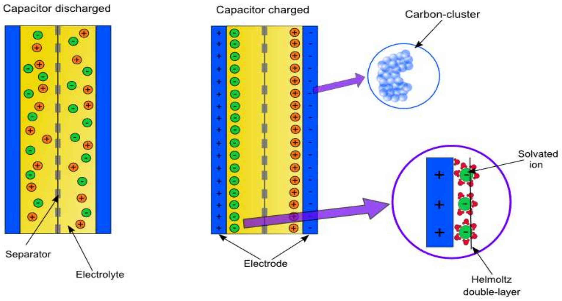
Figure 1.
Supercapacitor physical composition and internal work mode.
Figure 1.
Supercapacitor physical composition and internal work mode.
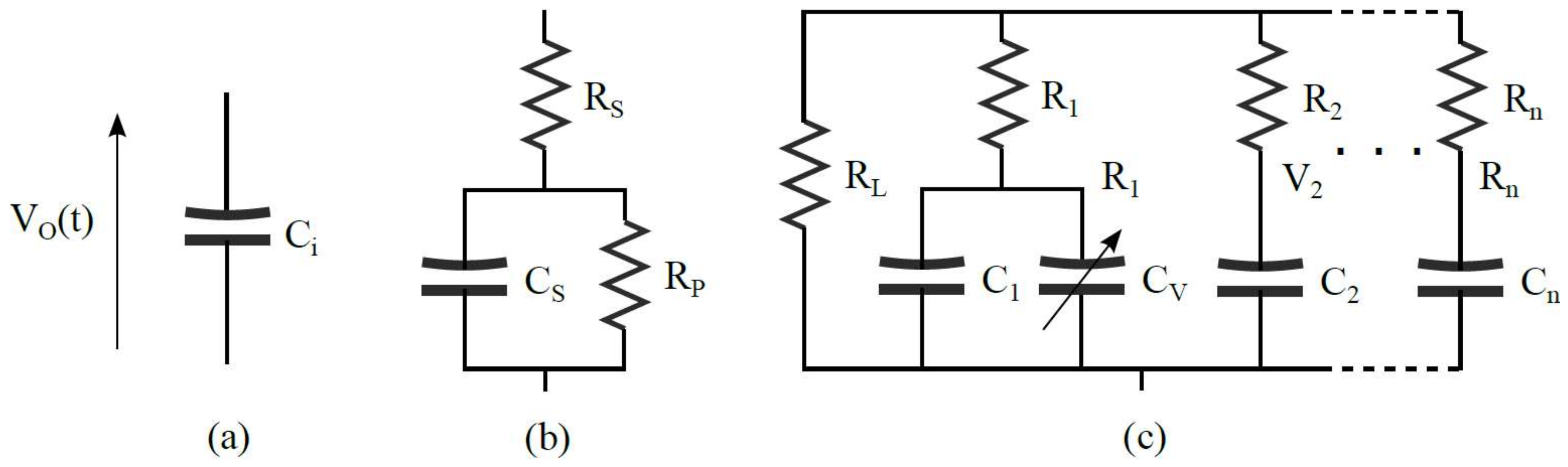
Figure 2.
Circuit-based supercapacitor models: (a) an ideal capacitor. (b) Simplified model including a series and parallel resistance. (c) RC ladder circuit with a voltage-dependent capacitance in its first branch, which may be extended to n branches.
Figure 2.
Circuit-based supercapacitor models: (a) an ideal capacitor. (b) Simplified model including a series and parallel resistance. (c) RC ladder circuit with a voltage-dependent capacitance in its first branch, which may be extended to n branches.
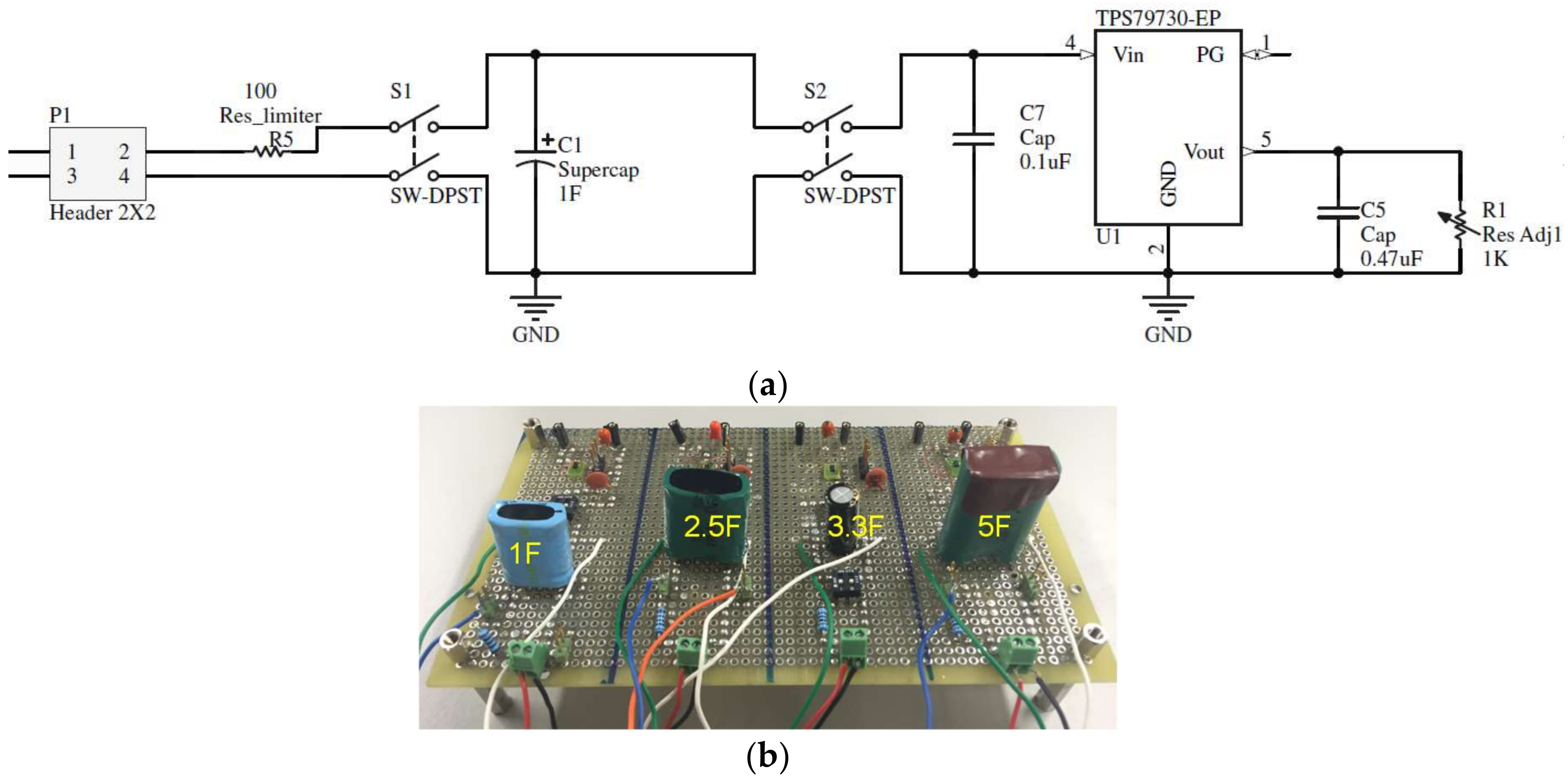
Figure 3.
Evaluation board set-up. (a) Schematic of a single capacitor test fixture. (b) Complete test evaluation board.
Figure 3.
Evaluation board set-up. (a) Schematic of a single capacitor test fixture. (b) Complete test evaluation board.
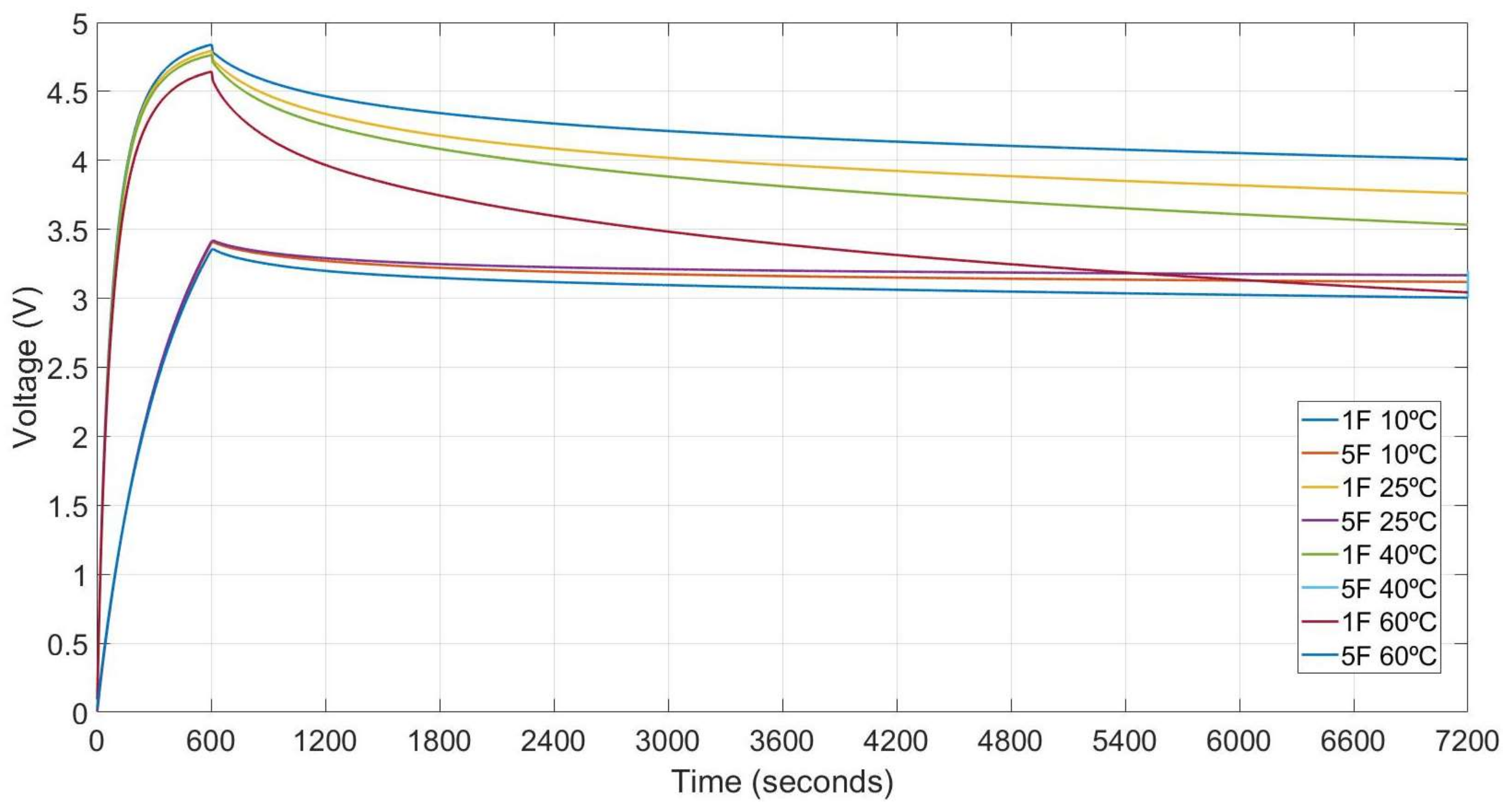
Figure 4.
Charge and discharge profiles at 10, 25, 40 and 60 °C for supercapacitors of 1 and 5 F.
Figure 4.
Charge and discharge profiles at 10, 25, 40 and 60 °C for supercapacitors of 1 and 5 F.
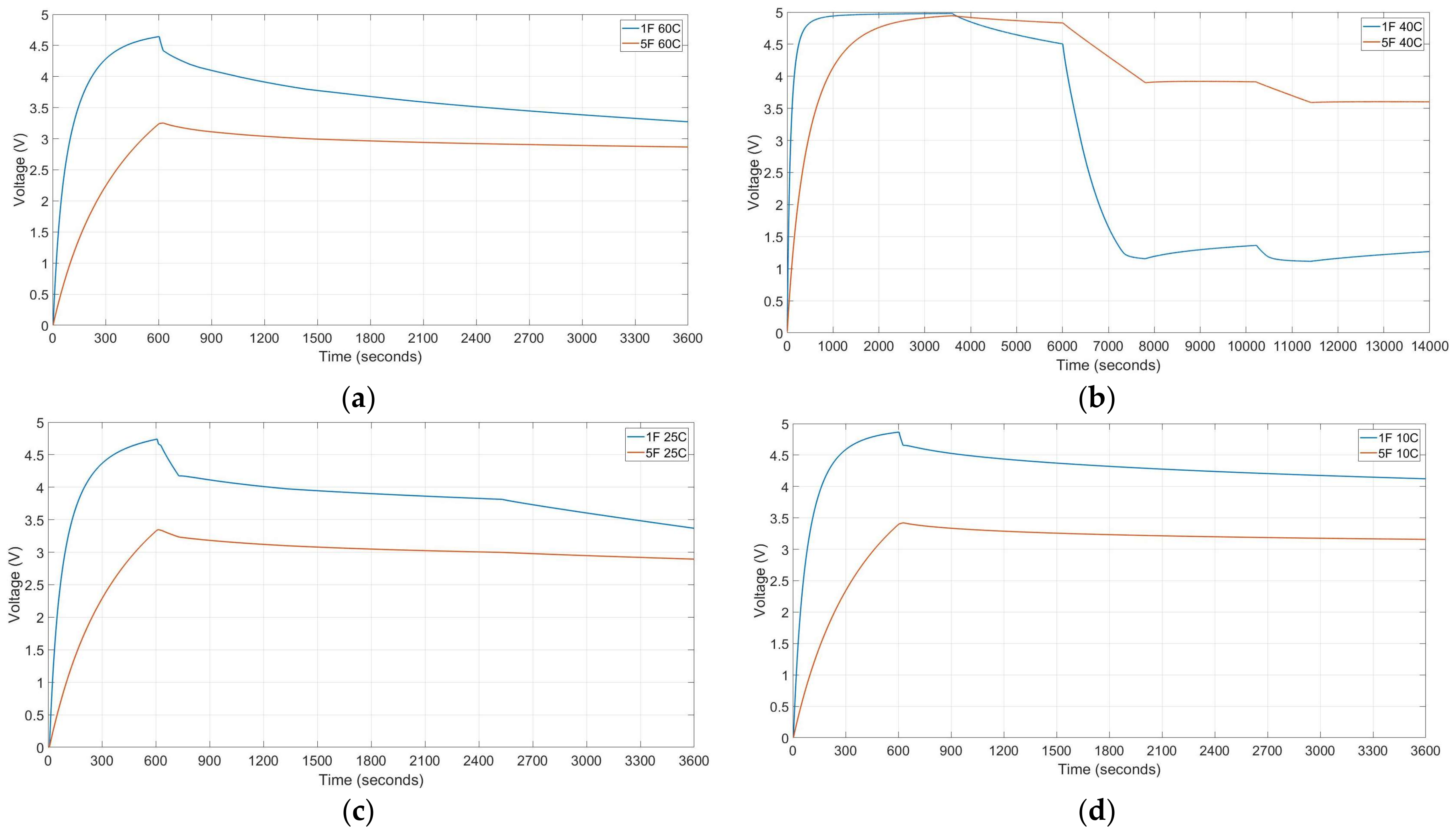
Figure 5.
Charge and discharge profiles of 1 and 5 F supercapacitor at different test conditions. (a) T = 25 °C, tcharge = 600 s, Vcharge = 5 V, discharge profile (5 steps of Ileak 30 s, 3 mA 90 s, 0.058 mA 600 s, Ileak 1200 s and 0.3 mA until discharge). (b) T = 40 °C, tcharge = 3600 s, Vcharge = 5 V, discharge profile (five steps: Ileak 2400 s, 3 mA 1800 s, 0.025 mA 2400 s, 1.5 mA 1200 s, Ileak until discharge). (c) T = 60 °C, tcharge = 600 s, Vcharge = 5 V, discharge profile (3 steps: 0.3 mA 180 s, 0.1 mA 600 s, 0.058 mA until discharge). (d) T = 10 °C, tcharge = 600 s, Vcharge = 5 V, discharge profile (single step: 0.02 mA until discharge).
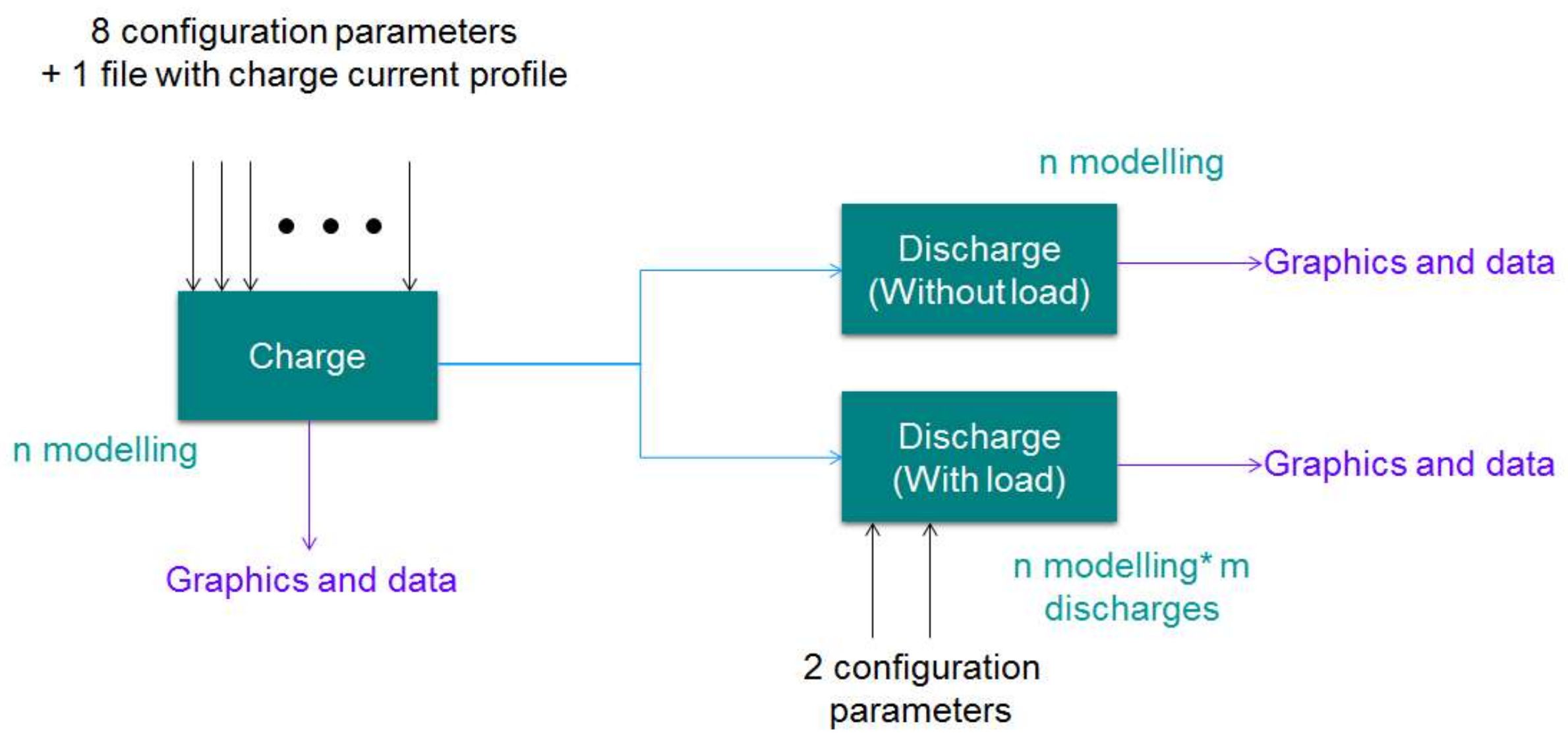
Figure 6.
Model architecture represented as a block diagram, including the program inputs and outputs.
Figure 6.
Model architecture represented as a block diagram, including the program inputs and outputs.
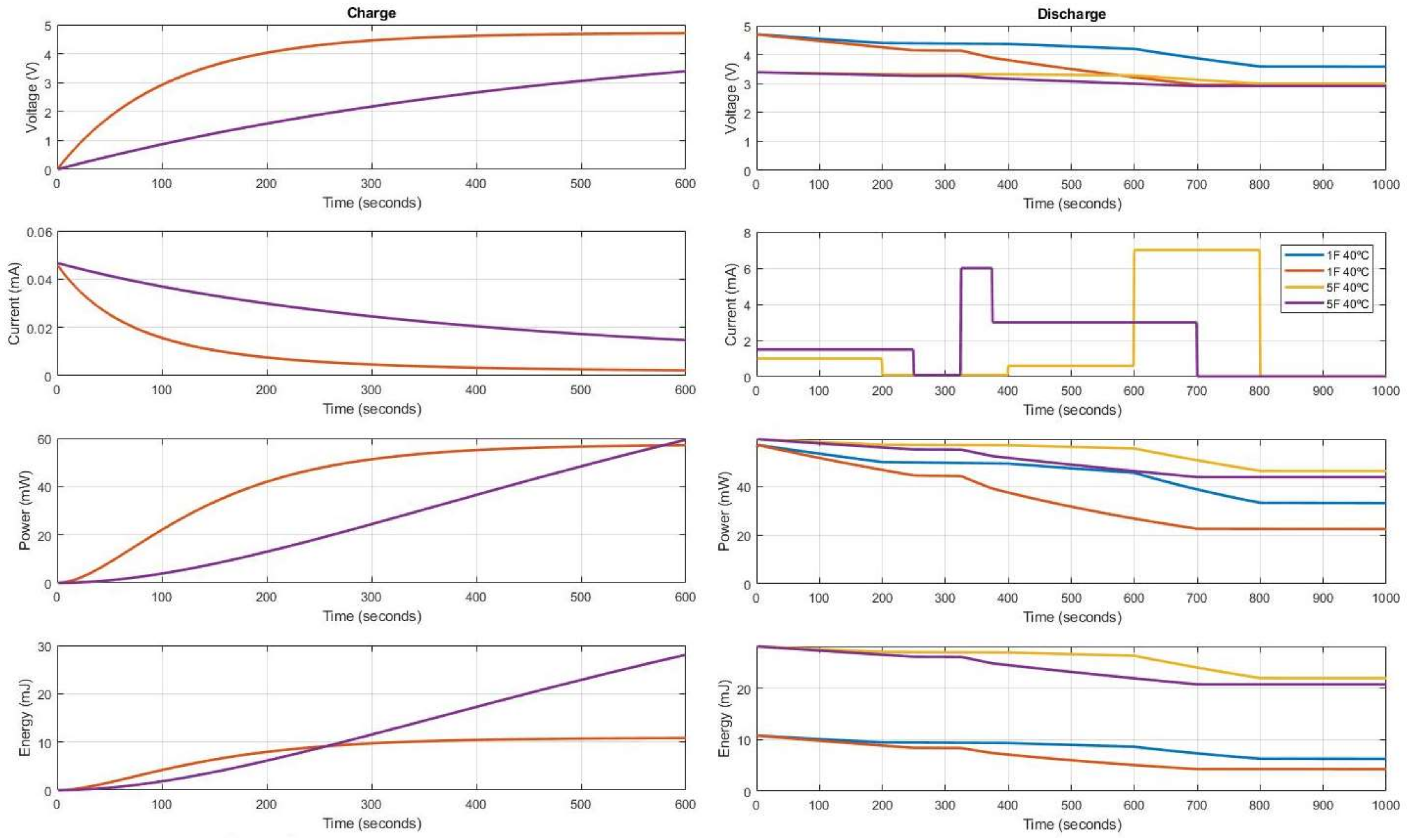
Figure 7.
Mathematical model results with 1 F and 5 F supercapacitors, 600 s charge with 5 V at 40 °C temperature and different profiles of discharge. Yellow discharge profile has five steps all with 200 s of duration; First 1 mA, second self-discharge, third 0.5 mA, fourth 7 mA and fifth self-discharge. Purple discharge profile has also 5 steps; First 1.5 mA for 250 s, second self-discharge for 75 s, third 6 mA for 50 s, fourth 3.5 mA for 325 s and fifth self-discharge for 300 s.
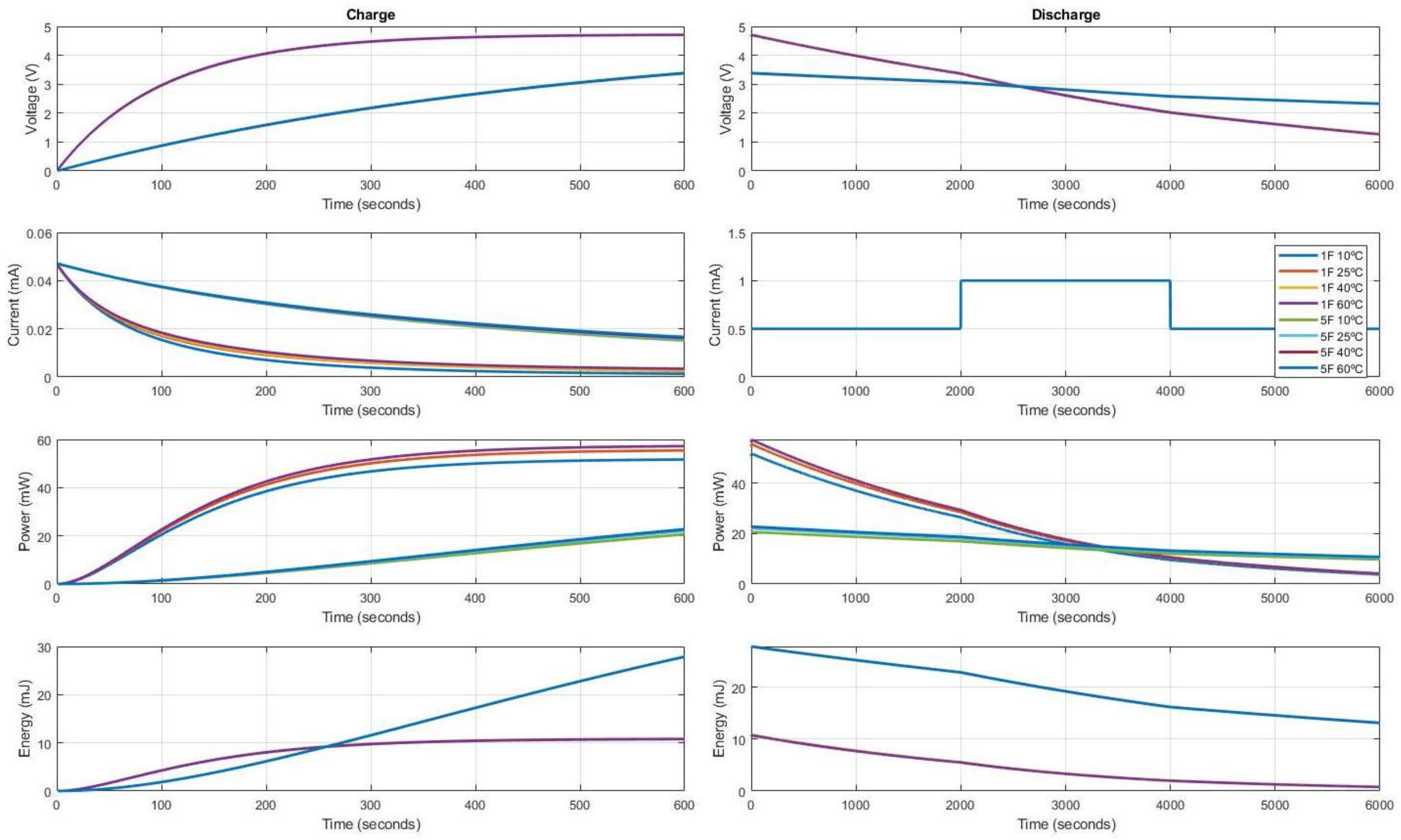
Figure 8.
Charge and discharge results obtained with the mathematical model for 1 F and 5 F supercapacitor values at different temperatures (10, 25, 40 and 60 °C), 600 s charge with 5 V and same outer profile consumption composed by three steps; First step 0.5 mA for 2000 s, second step 1 mA during also 2000 s and third step as first one.
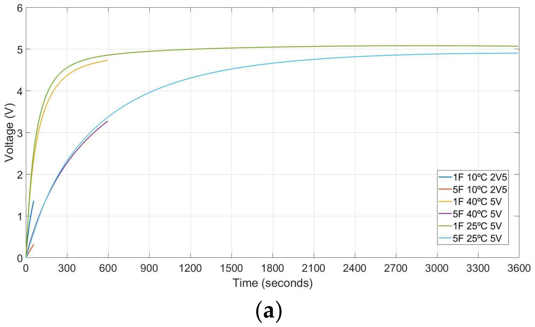
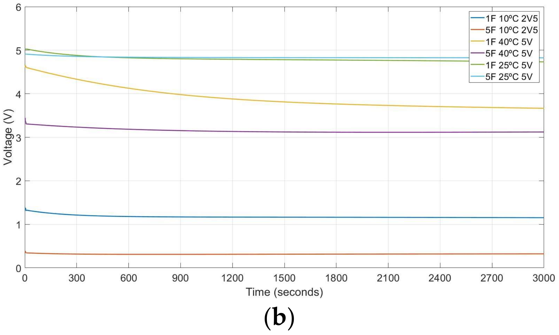
Figure 9.
Obtained results with 3rd approach. (a) Charge curves at different conditions and their (b) self-discharge profiles.
Figure 9.
Obtained results with 3rd approach. (a) Charge curves at different conditions and their (b) self-discharge profiles.
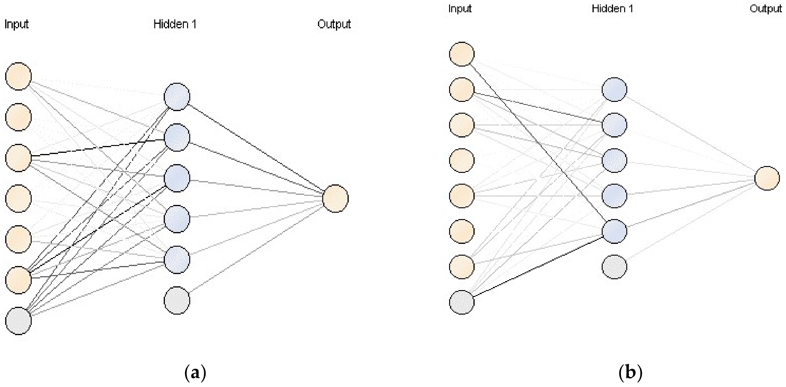
Figure 10.
Neuronal networks topologies generated during the experimental analysis. (a) Charge neuronal network topology for all conditions. (b) Discharge neuronal network topology when charge time is 60 s.
Figure 10.
Neuronal networks topologies generated during the experimental analysis. (a) Charge neuronal network topology for all conditions. (b) Discharge neuronal network topology when charge time is 60 s.
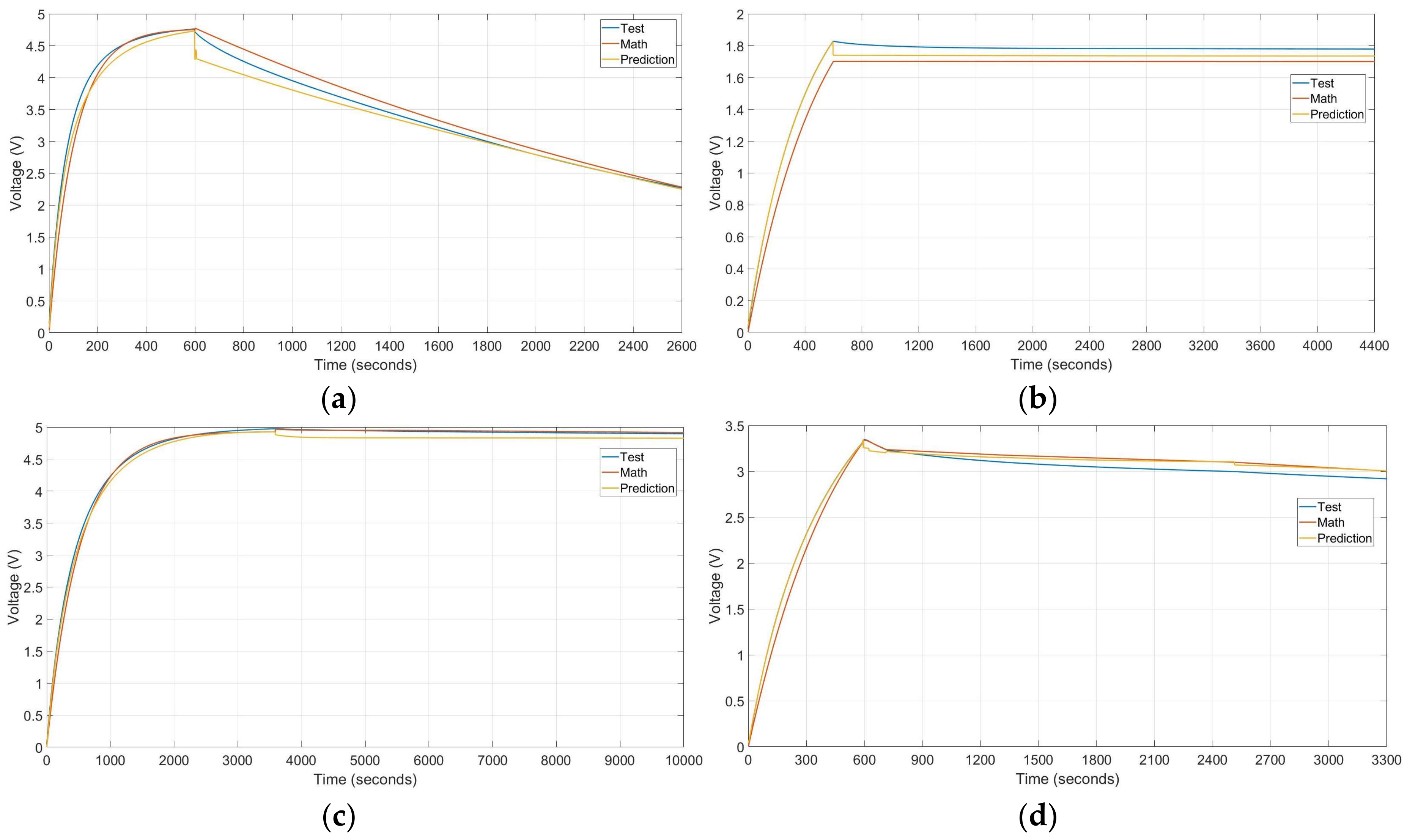
Figure 11.
Graphic results and comparisons of described -four different tests. (a) 1 Farad supercapacitor charged through 10 min with 5 V at 40 °C and 1 mA consumption discharge, (b) 5 Farad supercapacitor charged for 10 min with 2.5 V at 25 °C and self-discharge procedure, (c) 1 Farad supercapacitor charge during 1 h with 5 Volt at 10 °C and self-discharge procedure, (d) 5-Farad supercapacitor charge through 10 min with 5 V at 40 °C temperature and three discharge steps: 0.3 mA consumption through 3 min, 0.1 mA consumption through 10 min and self-discharge.
Table 1.
List of variables and test conditions.
Table 1.
List of variables and test conditions.
| Variable | Temperature (°C) | Charge Voltage (V) | Charge Time (s) | Supercapacitor Values (F) | Discharge Time (s) |
|---|
| Test conditions | 10, 25, 40, 60 | 2.5, 5 | 60, 600, 3600 | 1 F, 5 F | Infinity load, fixed value load, variable load steps |
Table 2.
Setting configuration for the MLP network.
Table 2.
Setting configuration for the MLP network.
| Parameter | Description | Value |
|---|
| hidden_layers | Name and size of the hidden layers. | (number of attributes + number of classes)/2 + 1 |
| training_cylces | Number of training cycles used for the training phase. | 500 |
| learning_rate | Weight rate change of each step | 0.3 |
| momentum | It adds a fraction of the previous weight update to the current one. | 0.2 |
| decay | Flag to decrease or not the learning rate | False |
| shuffle | Flag to shuffle or not the data before learning | Yes |
| normalize | The Neural Net operator uses a usual sigmoid function as the activation function. Therefore, the value range of the attributes should be scaled to −1 and +1. This can be done through the normalize parameter. Normalization is performed before learning. Although it increases runtime, but it is necessary in most cases | Yes |
| error_epsilon | optimization training error target value. | 1 × 10⁻⁵ |
| use_local_random_seed | Flag to use a random seed for randomization | No |
| local_random_seed | Local random seed. It is only used if use_local_random_seed is set to TRUE | - |
Table 3.
Variables used for the development of the prediction models.
Table 3.
Variables used for the development of the prediction models.
| Variable | Data Type | Values |
|---|
| Time | Integer | |
| Temperature (°C) | Integer | 10, 25, 40, 60 |
| Voltage (V) | Integer | 2.5, 5 |
| Charge Time (s) | Integer | 60, 600, 3600 |
| Capacitance | Integer | 1 F, 5 F |
| Charge current | Real | [0–45] mA |
Table 4.
Obtained statistical results in different approaches and at different conditions.
Table 4.
Obtained statistical results in different approaches and at different conditions.
| Variable | Data Type | Values | RMSE | Sd |
|---|
| 1st | Charge | For all conditions of the test | 0.007 | 0.005 |
| Discharge | For all conditions of the test | 0.222 | 0.035 |
| 2nd | Discharge | Charge-Time (60) | 0.007 | 0.002 |
| Charge-Time (600) | 0.232 | 0.091 |
| Charge-Time (3600) | 0.111 | 0.024 |
| 3rd | Discharge and charge curve at the same model | Charge-Time (60) | 0.021 | 0.002 |
| Charge-Time (600) | 0.213 | 0.071 |
| Charge-Time (3600) | 0.244 | 0.098 |
Table 5.
Obtained statistical errors from prediction and electro-mathematical models on three described tests and the average of 36 tests.
Table 5.
Obtained statistical errors from prediction and electro-mathematical models on three described tests and the average of 36 tests.
| | Statistical Technique | (a) Example | (b) Example | (c) Example | (d) Example | Average All |
|---|
| Pred. | Math | Pred. | Math | Pred. | Math | Pred. | Math | Pred. | Math. |
|---|
| Charge | RMSE | 0.137 | 0.204 | 0.113 | 0.178 | 0.007 | 0.145 | 0.005 | 0.134 | 0.052 | 0.146 |
| MSE | 0.019 | 0.042 | 0.013 | 0.032 | 0.0001 | 0.021 | 0.00002 | 0.018 | 0.005 | 0.023 |
| MAE | 0.123 | 0.125 | 0.103 | 0.167 | 0.006 | 0.114 | 0.004 | 0.118 | 0.047 | 0.101 |
| MAPE | 3.606 | 5.354 | 4.689 | 11.642 | 0.655 | 4.387 | 1.514 | 8.607 | 3.549 | 5.712 |
| Discharge | RMSE | 0.119 | 0.123 | 0.071 | 0.083 | 0.157 | 0.048 | 0.074 | 0.086 | 0.099 | 0.134 |
| MSE | 0.014 | 0.015 | 0.005 | 0.007 | 0.025 | 0.002 | 0.005 | 0.007 | 0.017 | 0.031 |
| MAE | 0.079 | 0.111 | 0.064 | 0.078 | 0.143 | 0.047 | 0.069 | 0.081 | 0.090 | 0.128 |
| MAPE | 2.013 | 3.210 | 2.211 | 2.653 | 3.659 | 1.230 | 2.272 | 2.685 | 2.819 | 3.792 |
Table 6.
Comparison between this work and other model.
Table 6.
Comparison between this work and other model.
| Model Type | Ref. Numb. | Statistical Error | Ref. Result | This Work Result |
|---|
| Electro-mathematical | [12] | Deviation | 3–7% | 2.35% |
| Electro-mathematical | [34] | Deviation | 2.56% | 2.35% |
| Electro-mathematical | [35] | RMSE | 0.65 | 0.071–0.204 |
| M.L. → ANN | [23] | MSE | 0.089 | 0.005–0.017 |
| M.L. → Kalman Filtering | [36] | MAE | 0.50 | 0.047–0.090 |
| RMSE | 0.63 | 0.052–0.099 |

 ,
, 


