Article

A Compact Semi-Circular and Arc-Shaped Slot Antenna for Heterogeneous RF Front-Ends

1
Department of Electronics, University of Ferhat Abbas, Sétif 1, Sétif 19000, Algeria
2
School of Electrical Engineering and Computer Science, University of Bradford, Bradford BD71DP, UK
3
Department of Electrical Engineering, University of 20 Aout 1955—Skikda, Skikda 21000, Algeria
4
Instituto de Telecomunicações, Campus Universitário de Santiago, 3810-193 Aveiro, Portugal
5
Centre for Wireless Technology, Faculty of Engineering, Multimedia University, Cyberjaya 63100, Malaysia
6
Information and Communication Engineering Department, Basrah University College of Science and Technology, Basrah 24001, Iraq
*
Author to whom correspondence should be addressed.
Submission received: 22 August 2019 / Revised: 23 September 2019 / Accepted: 1 October 2019 / Published: 6 October 2019
(This article belongs to the Special Issue Recent Technical Developments in Energy-Efficient 5G Mobile Cells)

Abstract

:
In this paper, a new miniaturized compact dual-band microstrip slot antenna is presented. To achieve the dual-band characteristics, two adjunct partial arc-shaped small slots are joined to two main circular slots embedded in the ground of the antenna structure. With a reduced size of 30 × 28.5 × 0.8 mm3, the proposed antenna presents a dual-band characteristic. The design is optimized using a High Frequency Structure Simulator (HFSS) followed by experimental verifications. An impedance bandwidth, for S11 ≤ 10 dB, that covers the 1.8 GHz and 2.4 GHz bands is accomplished, which makes the proposed antenna basically suitable for hand-held devices and medical applications. More applications such as digital communication system (DCS) 1.71–1.88 GHz, personal communication services (PCS) 1.85–1.99 GHz, Universal and mobile telecommunications system UMTS 1.92–2.17 GHz, Bluetooth 2.4–2.5 GHz, and Wi-Fi 2.4–2.454 GHz, Industrial Scientific and Medical radio frequency (RF) band ISM-2.4 GHz, Wireless Local Area Network (WLAN-2.4) are possible by simply changing one of the geometrical antenna dimensions. The antenna is characterized by stable radiation patterns as well.

1. Introduction

Conventional microstrip antennas have the attractive features of a low profile, light weight, ease of analysis and fabrication, and ease of integration into microwave devices. However, they exhibit some limitations such as single resonance frequency, low impedance bandwidth, low gain, larger size, and polarization impurity. Among the planar antenna structures, the slot antenna is one of the most promising candidates for multi-band antenna applications because, in addition to the aforementioned attractive qualities, they inherently possess larger bandwidths and occupy less space which makes them promising components for microwave applications [1,2,3,4,5,6,7,8,9,10]. In this frame, various designs of multi-band slot antennas have been proposed [11,12,13,14,15,16,17,18,19]. Moreover, several techniques have been proposed in the literature to enhance the parameters of conventional microstrip slot antennas and realize the multi-band function, these include using new feeding techniques [20], Defected Ground Structures (DGS) [10,21,22,23], parasitic elements [24,25], Metamaterial [26,27], etc. Dual or multi-band characteristics are in great demand for various applications such as wireless local area networks (Bluetooth, WLAN, and WiMAX) and Industrial Scientific and Medical (ISM) applications. In modern communication standards a single antenna system that can cover all these bands is considered highly necessary, not only to cover several frequency bands but also to reduce the physical size of the system. A literature survey shows that planar slot antennas are promising candidates to realize broadband or multi-band functions to cover up multi-standard services. Several dual- and/or multi-band slot antenna designs have demonstrated their superior performances for the desired multi-band requirements [28,29]. A compact CPW-fed triple-band antenna for diversity applications is reported in [30], triple-band antennas in [31,32] and quad-band in [33,34] and broad-band circular polarization [35], for example. The dual-band characteristic of these kind of antennas may be achieved by joining small resonant slots to the body of the main one [36] or etching several stubs on the large slots [14]. Slot antennas triple-band characteristic is also possible by etching three folded slots on the ground plane such as the designs reported in [15,16], or several stubs on the slots [17]. Quad-band slot antennas are also possible using the above mentioned techniques [3,19]. Better impedance matching may be achieved by inserting open-ended stubs [37]. Generally speaking, slot antennas have larger bandwidth (BW) than the microstrip antennas because of their lower quality factors due to the bidirectional radiation characteristics [4,35]. Combinations of slots and strips on the feeding side can generate circular polarization [4].
In this paper, we present the technique of introducing small arc-shaped slots in the antenna structure to realize a new high gain miniaturized dual-band radiating antenna. The antenna design consists of two main semi-circular slots. Two adjunct small arc-shaped slots are asymmetrically and partially etched round these two main slots to realize the dual-band function and obtain a small sized-structure. The antenna is fed by a stubbed microstrip line for a better impedance matching in the operating bands. The proposed slot antenna covers the desirable 1.8 GHz and 2.4 GHz bands for hand-held devices and medical applications.

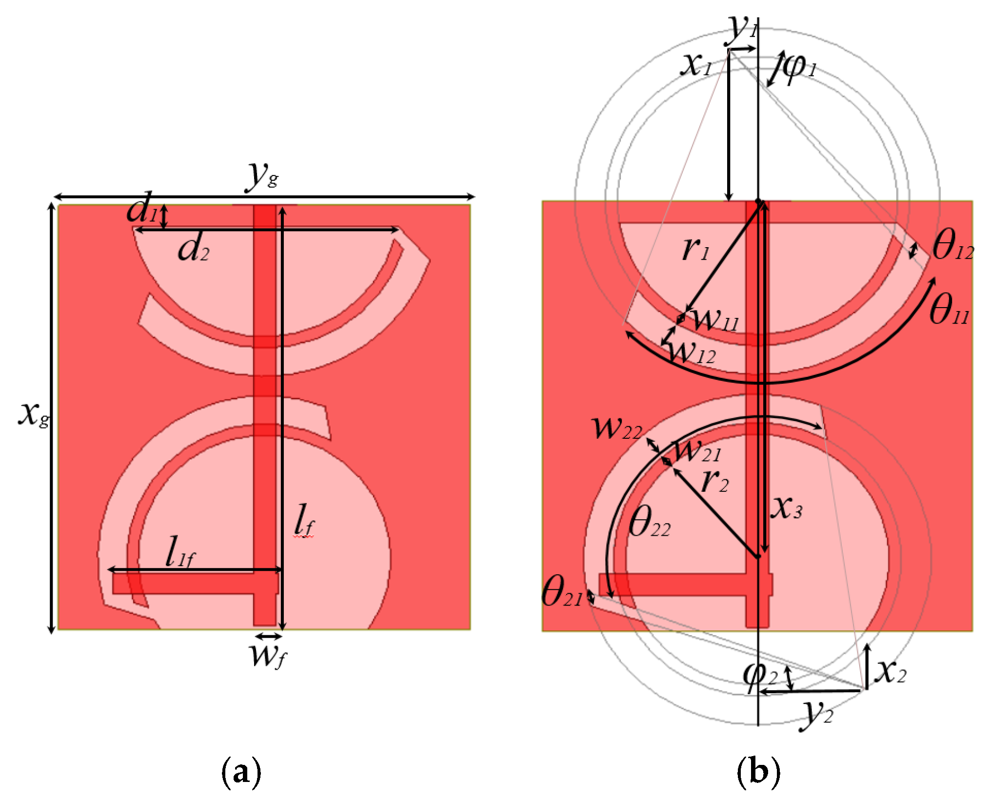
2. Proposed Antenna Geometry and Summarized Results

The geometry of the slot antenna design is shown in Figure 1. In this design, two main semi-circular slots are etched on a copper plane. A feeding L-shaped 50 Ω microstrip line is printed on the other side of the substrate as this approach enables ease of impedance matching and other useful features [38]. The feed line is stubbed for a better impedance matching. Two adjunct arc-shaped slots are asymmetrically etched partially round the two slots. Two angular parameters: θ11 + θ12 and θ21 + θ22 are attributed to the two arc-shaped slots to control their locations, lengths and widths with the aid of the parameters r1, φ1 and r2, φ2, respectively. The whole structure is designed and realized on an FR4 30 × 28.5 × 0.8 mm3 substrate with a relative permittivity εrs = 4.4 and loss tangent of 0.017.
The antenna simulations were carried out using High Frequency Structure Simulator (HFSS) software. The final antenna dimensions are: xg = 30, yg = 28.5, d1 = 1.5, d2 = 18.45, lf = 29.75, wf = 1.5, l1f = 11.5, θ11 = 60°, θ12 = 2.5°, θ22 = 60°, θ21 = 2.5°, φ1 = 47.23°, φ2 = 17.5°, r1 = 9.3, w11 = 0.8, w12 = 1.95, r2 = 8.75, w21 = 0.8, w22 = 1.9, x1 = 10.59, y1 = 1.87, x2 = 4.03, y2 = 7.20, x3 = 25 (all dimensions are in mm). All the parameters are clearly represented in Figure 1.

2.1. Effect of the Main Slots and Adjunct Arc-Shaped Slots

The objective of this work is to realize a miniaturized dual-band antenna that covers the bands 1.8 GHz and 2.4 GHz for mobile and medical applications, and solutions with stable radiation patterns. In order to examine the effect of introducing the semi-circular slots and arcs in the radiating structure, the different steps of the antenna design procedure and the comparative study results are presented by Figure 2, Figure 3 and Figure 4. The first antenna (Figure 2a) is a structure with simple partial circular slots etched in the ground plane and the second one (Figure 2b) is the final proposed structure, where two additional arc-shaped slots are cut round the two main slots. Figure 3a,b shows the S11 coefficient and gain, respectively, for the two structures. The first antenna shows a better return loss coefficient at about 2.2 GHz with a gain varying between 1.04 dBi and 4.9 dBi in the frequency range 1.75–4 GHz. The final structure (Figure 2b) manifests itself as a dual-band antenna that operates at the desired 1.8 GHz and 2.4 GHz bands with simulated gains of 3.43 and 4.47 dBi, respectively.
The second study aims to investigate the response of the circular slots with arcs according to Figure 4 configuration steps. Three different antennas are designed. In the first structure (Figure 4a), only the slot in the first side of the antenna near the sub miniature version A (SMA) port is considered. In the second structure (Figure 4b), we only consider the slot at the other side of the structure and in Figure 4c, we consider both slots forming our final proposed antenna.
Figure 5a,b shows the compared simulation results of S11 coefficients and gains. We notice that the two antennas (a) and (b) are basically mono-band and present operating bands centered at 1.95 GHz and 2.0 GHz, respectively. Moreover, antenna (b) exhibits a very poor gain. The effect of the two main slots and adjunct arc-shaped slots is clear on the properties of the antennas.

2.2. Equivalent Circuit Model

In order to analyze the true behavior of the system, co-simulation of the antenna and other RF front-end components is necessary. It is necessary to draw the equivalent circuit model of the antenna, because time domain simulators such as Advanced Design System (ADS) and SPICE are used for majority of the RF front-end design. The equivalent circuit model of the proposed dual-band antenna is shown in Figure 6a. We excited two modes of the antenna using microstrip transmission line in the electromagnetic (EM) model simulations. The two modes of the antenna are represented by the two resistor, inductor and capacitor (RLC) section in the equivalent circuit model [39] as shown in Figure 6a. The coupling associated between two modes of the antenna is represented as the resonant circuit (LC) section [40]. The LC section is responsible for the strong or weak coupling between the modes. The impedance transformer shows the matching of the source with the antenna. The optimized components of the equivalent circuit model is illustrated in Figure 6a. The impedance results of the EM model and equivalent circuit model is compared in Figure 6b. We can see that the results match well in the two resonating modes. We can see that there are several modes in the EM model and only two modes in equivalent circuit model. The reason behind two modes in the equivalent circuit model is that we have designed our equivalent circuit model keeping in mind the two resonating modes only.

2.3. Parametric Study

A parametric study was carried out to examine the effects of the main slots as well as the arc-shaped ones on the size reduction coefficient and return loss of the antenna. A direct relationship between the slots parameters and the characteristics of the antenna is noticed. These parameters could control the antenna characteristics by modifying the radial and angular dimensions of the slots.
Note that the position and the size of the two arc-shaped slots are very influential. The characteristics of the antenna may be controlled using the two parameters φ1 and φ2 attributed to Arc1 and Arc2, respectively. While Arc1 has a significant effect around 1.8 GHz (Figure 7a,b) and can also realize a tri-band characteristic, Arc2 presents the same effect but around 2.4 GHz and helps shift the 1.8 GHz band towards higher frequencies.
The length of the two arcs as well as their widths (r1, r2, w11, and w12) have almost the same effect around 1.8 GHz, but only Arc1 can affect the S11 around 2.4 GHz (Figure 8a–d). The spacing between the arcs and the ground plane (w12 and w22) affects S11 in the same way. These remarks are certified by the behavior of the current density, which showed the relationship between the two arcs and the frequencies 1.8 GHz and 2.4 GHz (Figure 8e,f).
According to the proposed antenna parametric study, it is easy to reach any frequency in the band 1.8–2.6 GHz by simply modifying the dimensions of the antenna. Moreover, we can realize a single, double or triple band antenna centered at: 1.8, 1.9, 2, 2.2, 2.4, 2.5, and 2.6 GHz for digital communication system (DCS) (1.71–1.88 GHz), personal communication services (PCS) (1.85–1.99 GHz), UMTS (1.92–2.17 GHz), Bluetooth (2.4–2.5 GHz), Wi-Fi (2.4–2.454 GHz), ISM (2.4 GHz), and WLAN (2.4 GHz).
The surface current density at operating frequencies is investigated to better understand the operation mode of the proposed dual-band antenna, as shown in Figure 9a,b. Figure 9a shows that the highest current density is observed along the quarter length of the feed line and the two arc-shaped slots at 1.8 GHz. For 2.4 GHz, the current is mainly concentrated along the microstrip line and the two arc-shaped slots, as shown in Figure 9b. By analyzing the current flux plot at 1.8 and 2.4 GHz, we can conclude that coupling between the arc-shaped slots and the excitation line generates two simultaneous resonance frequencies.
Measuring the effective lengths corresponding to the current paths represented by the black lines in Figure 10, we find respectively: L1 = 57 mm which corresponds to a frequency of f1 = 2.51 GHz and L2 = 89 mm which corresponds to a frequency of f2 = 1.61 GHz.
According to the radiation pattern plots presented in Figure 11, it is noted that the antenna is omni-directional in the XY plane (H plane) with a weak cross polarization. In the XZ plane (E plane), the radiation pattern is stable with a weak cross polarization as well. Whereas, for the YZ plane, the cross polarization is slightly higher.
To validate the simulated results, an antenna prototype is realized as shown in Figure 12a,b and measurements were performed using an HP8510C vector network analyzer.
In general, and from Figure 13a,b, measurements of the dual-band antenna S11 coefficient and gain coincide well with simulations. For S11, a slight shift of less than 11 MHz between simulations and measurements is observed. For the gain, the obtained results of simulations and measurements for the two frequency bands are: 4.5 and 4.34 dB for 1.8 GHz and 5.29 and 5.09 dB for 2.4 GHz, respectively. The measured gains of the prototype were carried out in a far-field anechoic chamber using a calibrated EMCO type 3115 broadband horn as the reference antenna. The reference fixed antenna was a broadband horn (EMCO type 3115) positioned at 4 m from the antenna under test. We have scanned for three orthogonal planes. For each plane a co-polar and cross-polar gain components were measured.

2.4. Specific Absorption Rate (SAR) Analysis

As we have seen in the parametric analysis section, that the antenna can be used as a single, double or triple band antenna centered at: 1.8, 1.9, 2, 2.2, 2.4, 2.5, and 2.6 GHz, like Digital Cellular System DCS (1.71–1.88 GHz), PCS (1.85–1.99 GHz), UMTS (1.92–2.17 GHz), Bluetooth (2.4–2.5 GHz), and Wi-Fi (2.4–2.454 GHz) spectrum Industrial Scientific and Medical radio frequency band (ISM–2.4 GHz), Wireless Local Area Network (WLAN-2.4). The above mentioned bands are commonly used in hand-held modern devices. It is useful to study the impact of the electromagnetic radiations on the human body at these frequencies.
In this work, we only studied the SAR for 1.8 and 2.4 GHz. We modeled a three layer human model using properties of skin, fat and muscle [41,42] as shown in Figure 14a. We placed the antenna at a distance of 5 mm from the skin to avoid direct contact with the skin layer. As can be seen from the Figure 14b, the proposed antenna has 10-g peak SAR values of 1.49 and 1.33 W/kg at 1.8 and 2.4 GHz, respectively for input power of 1 W. According to IEEE C95.1-2005, the SAR values should not exceed 2 W/kg for 10-g sample and 1.6 W/kg for 1-g sample [43]. From the peak SAR values, it is clear that the proposed antenna is safe to be used in the any hand-held device with input power not more than 1.34 W.
Let us conclude this part with a comparison of the size, operating bands and gain of our antenna with those realized or simulated available in the literature. It is clear from Table 1 that our proposed structure presents a good compromise between miniaturization and the significant gain obtained compared to the reported studies. Our antenna structure is well miniaturized and has the best ratio gain/size. By comparing with higher gain antenna cases, close to ours, presented in [2,5,6,17,23,44], our proposed antenna size is reduced by more than three times. However, for reported antennas with size close to ours [3,9,10,13,18,26,30,45,46], the proposed antenna presents a higher gain.

3. Conclusions

In this work, we proposed a new slot antenna design for dual-band operation. Two adjunct arc-shaped slots are added to two main semi-circular slots, all etched on the ground plane to realize an appropriate adjustment of the desired frequency bands. Thus, two resonant frequencies centered at 1.8 and 2.4 GHz have been achieved resulting in a dual-band antenna. A radiation peak gain of 4.39/5.09 dB has been obtained. The key design advantages, including size reduction, simple configuration, adequate gain, and dual-band feature make the proposed antenna an excellent candidate with potential features for current and future applications.

Author Contributions

Design and concept, C.Z. and D.S.; methodology, C.Z. and I.E.; investigation, A.I., W.F.A.M. and C.Z.; resources, I.E. and J.R.; writing—original draft preparation, C.Z.; writing—review and editing, R.A.-A., I.E., J.K., and A.I.; validation, visualization, R.A.-A.; supervision, J.R.; project administration, J.R.

Funding

This project has received funding from the European Union’s Horizon 2020 research and innovation program under grant agreement H2020-MSCA-ITN-2016 SECRET-722424. This work is also funded by the FCT/MEC through national funds and when applicable co-financed by the ERDF, under the PT2020 Partnership Agreement under the UID/EEA/50008/2019 project.

Acknowledgments

This work is supported by the European Union’s Horizon 2020 Research and Innovation program under grant agreement H2020-MSCA-ITN-2016-SECRET-722424. This work is part of the POSITION-II project funded by the ECSEL joint Undertaking under grant number Ecsel-7831132-Postitio-II-2017-IA, www.position-2.eu.

Conflicts of Interest

The authors declare no conflict of interest.

References

  1. Tang, M.C.; Shi, T.; Ziolkowski, R.W. Planar ultrawideband antennas with improved realized gain performance. IEEE Trans. Antennas Propag. 2015, 64, 61–69. [Google Scholar] [CrossRef]
  2. Chen, W.-S.; Wong, K.-L. Dual-frequency operation of a coplanar waveguide-fed dual-slot loop antenna. Microw. Opt. Technol. Lett. 2001, 30, 38–40. [Google Scholar] [CrossRef]
  3. Cao, Y.F.; Cheung, S.W.; Yuk, T.I. A multi-band slot antenna for GPS/WiMAX/WLAN systems. IEEE Trans. Antennas Propag. 2015, 63, 952–958. [Google Scholar] [CrossRef]
  4. Kunwar, A.; Gautam, A.K.; Kanaujia, B.K.; Rambabu, K. Circularly polarized D-shaped slot antenna for wireless applications. Int. J. RF Microw. Comput.-Aided Eng. 2019, 29, e21498. [Google Scholar] [CrossRef]
  5. Sze, J.-Y.; Hsu, C.-I.G.; Hsu, S.-C. Dual-broadband multistandard printed slot antenna with a composite back-patch. Microw. Antennas Propag. 2008, 2, 205–209. [Google Scholar] [CrossRef]
  6. Hassan, N.; Zakaria, Z.W.; Sam, Y.; Hanapiah, I.N.M.; Mohamad, A.N.; Roslan, A.F.; Aziz, M.Z.A. A Design of dual-band microstrip patch antenna with right-angle triangular aperture slot for energy transfer application. Int. J. RF Microw. Comput.-Aided Eng. 2019, 29, e21666. [Google Scholar] [CrossRef]
  7. Zebiri, C.; Lashab, M.; Sayad, D.; Elfergani, I.E.; Ali, A.; Khambashi, M.A.; Abd-Alhameed, R. Bandwidth Enhancement of rectangular dielectric resonator antenna using circular and sector slot coupled technique. In Proceedings of the 12th European Conference on Antennas and Propagation (EuCAP 2018), London, UK, 9–13 April 2018. [Google Scholar]
  8. Elfergani, I.; Hussaini, A.S.; Rodriguez, J.; Abd-Alhameed, R. (Eds.) Antenna Fundamentals for Legacy Mobile Applications and Beyond, 1st ed.; Springer: Cham, Switzerland, 2018. [Google Scholar] [CrossRef]
  9. Upadhyaya, T.; Desai, A.; Patel, R. Design of printed monopole antenna for wireless energy meter and smart applications. Prog. Electromagn. Res. Lett. 2018, 77, 27–33. [Google Scholar] [CrossRef]
  10. Patel, R.; Desai, A.; Upadhyaya, T. An electrically small antenna using defected ground structure for RFID, GPS and IEEE 802.11 a/b/g/s applications. Prog. Electromagn. Res. Lett. 2018, 75, 75–81. [Google Scholar] [CrossRef]
  11. Li, K.; Dong, T.; Xia, Z. Wideband Printed Wide-Slot Antenna with Fork-Shaped Stub. Electronics 2019, 8, 347. [Google Scholar] [CrossRef]
  12. Ojaroudi, N.; Ghadimi, N. Design of CPW-fed slot antenna for MIMO system applications. Microw. Opt. Technol. Lett. 2014, 56, 1278–1281. [Google Scholar] [CrossRef]
  13. Tanweer, A.; Muzammil, M.; Biradar, R.C. A multi-band reconfigurable slot antenna for wireless applications. AEU-Int. J. Electron. Commun. 2018, 84, 273–280. [Google Scholar]
  14. Chiang, M.J.; Wang, S.; Hsu, C.C. Compact multifrequency slot antenna design incorporating embedded arc-strip. IEEE Antennas Wirel. Propag. Lett. 2012, 11, 834–837. [Google Scholar] [CrossRef]
  15. Saghati, A.P.; Azarmanesh, M.; Zaker, R. A novel switchable singleand multifrequency triple-slot antenna for 2.4-GHz bluetooth, 3.5-GHz WiMax, and 5.8-GHz WLAN. IEEE Antennas Wirel. Propag. Lett. 2010, 9, 534–537. [Google Scholar] [CrossRef]
  16. Lu, J.H.; Huang, B.J. Planar compact slot antenna with multi-band operation for IEEE 802.16 m application. IEEE Trans. Antennas Propag. 2013, 61, 1411. [Google Scholar] [CrossRef]
  17. Dang, L.; Lei, Z.Y.; Xie, Y.J.; Ning, G.L.; Fan, J. A compact microstrip slot triple-band antenna for WLAN/WiMAX applications. IEEE Antennas Wirel. Propag. Lett. 2010, 9, 1178–1181. [Google Scholar] [CrossRef]
  18. Tanweer, A.; Prasad, K.D.; Biradar, R.C. A miniaturized slotted multi-band antenna for wireless applications. J. Comput. Electron. 2018, 17, 1–15. [Google Scholar]
  19. Bod, M.; Hassani, H.R.; Taheri, M.M. Compact UWB printed slot antenna with extra bluetooth, GSM, and GPS bands. IEEE Antennas Wirel. Propag. Lett. 2012, 11, 531–534. [Google Scholar] [CrossRef]
  20. Khandelwal, M.K.; Kanaujia, B.K.; Kumar, S. Defected ground structure: Fundamentals, analysis, and applications in modern wireless trends. Int. J. Antennas Propag. 2017. [Google Scholar] [CrossRef]
  21. Jaiswal, A.; Sarin, R.K.; Raj, B.; Sukhija, S. A novel circular slotted microstrip-fed patch antenna with three triangle shape defected ground structure for multi-band applications. Adv. Electromagn. 2018, 7, 56–63. [Google Scholar] [CrossRef]
  22. Tahar, F.; Barakat, A.; Saad, R.; Yoshitomi, K.; Pokharel, R.K. Dual-Band Defected Ground Structures Wireless Power Transfer System with Independent External and Inter-Resonator Coupling. IEEE Trans. Circuits Syst. II Express Briefs 2017, 64, 1372–1376. [Google Scholar] [CrossRef]
  23. Lin, W.P.; Yang, D.H.; De Lin, Z. Compact dual-band planar inverted-e-shaped antenna using defected ground structure. Int. J. Antennas Propag. 2014. [Google Scholar] [CrossRef]
  24. Zbitou, J.; Errkik, A. Emerging Innovations in Microwave and Antenna Engineering; IGI Global: Hershey, PA, USA, 2018. [Google Scholar]
  25. Yunus, M.; Sinaga, T.J.; Fitri, I.; Wismiana, E.; Munir, A. Bowtie-shaped DGS for reducing coupling between elements of planar array antenna. In Proceedings of the 2017 International Symposium on Electronics and Smart Devices (ISESD), Yogyakarta, Indonesia, 17–19 October 2017; pp. 226–229. [Google Scholar]
  26. Pokkunuri, P.; Madhav, B.T.P.; Sai, G.K.; Venkateswararao, M.; Ganesh, B.; Tarakaram, N.; Teja, D. Metamaterial Inspired Reconfigurable Fractal Monopole Antenna for Multi-band Applications. Int. J. Intell. Eng. Syst. 2019, 12, 53–61. [Google Scholar]
  27. Saraswat, R.K.; Kumar, M. Miniaturized slotted ground UWB antenna loaded with metamaterial for WLAN and WiMAX applications. Prog. Electromagn. Res. 2016, 65, 65–80. [Google Scholar] [CrossRef]
  28. Hung, T.; Liu, J.; Wei, C. Dual-band circularly polarized aperture-coupled stack antenna with fractal patch for WLAN and WiMAX applications. Int. J. RF Microw. Comput. Aided Eng. 2014, 24, 130–138. [Google Scholar] [CrossRef]
  29. Desde, I.; Bozdag, G.; Kustepeli, A. Multi-band CPW fed MIMO antenna for bluetooth, WLAN, and WiMAX. Microw. Opt. Technol. Lett. 2016, 58, 1023–1026. [Google Scholar] [CrossRef]
  30. Wu, R.Z.; Wang, P.; Zheng, Q.; Li, R. Compact CPW-fed triple-band antenna for diversity applications. Electron. Lett. 2015, 51, 735–736. [Google Scholar] [CrossRef]
  31. Zhai, H.; Liu, L.; Ma, Z.; Liang, C. A printed monopole antenna for triple-band WLAN/WiMAX applications. Int. J. Antennas Propag. 2015. [Google Scholar] [CrossRef]
  32. Kumar, C.V.A.; Paul, B.; Mohanan, P. Compact Triband Dual F-Shaped Antenna for DCS/WiMAX/WLAN Applications. Prog. Electromagn. Res. 2018, 78, 97–104. [Google Scholar] [CrossRef]
  33. Tanweer, A.; Saadh, M.; Biradar, R.C. A fractal quad-band antenna loaded with L-shaped slot and metamaterial for wireless applications. Int. J. Microw. Wirel. Technol. 2018, 10, 826–834. [Google Scholar]
  34. Chu, H.B.; Shirai, H. A compact metamaterial quad-band antenna based on asymmetric E-CRLH unit cell. Prog. Electromagn. Res. C 2018, 81, 171–179. [Google Scholar] [CrossRef]
  35. Wu, J.; Ren, X.; Li, Z.; Yin, Y.Z. Modified square slot antennas for broadband circular polarization. Prog. Electromagn. Res. 2013, 38, 1–14. [Google Scholar] [CrossRef]
  36. Gangwar, S.P.; Gangwar, K.; Kumar, A. A compact modified hexagonal slot antenna for wideband applications. Electromagnetics 2018, 38, 339–351. [Google Scholar] [CrossRef]
  37. Naser-Moghadasi, M.; Sadeghzadeh, R.A.; Asadpor, L.; Soltani, S.; Virdee, B.S. Improved band-notch technique for ultra-wideband antenna. IET Microw. Antennas Propag. 2010, 4, 1886–1891. [Google Scholar] [CrossRef]
  38. Zebiri, C.-E.; Lashab, M.; Sayad, D.; Elfergani, I.T.E.; Sayidmarie, K.H.; Benabdelaziz, F.; Abd-Alhameed, R.A.; Rodriguez, J.; Noras, J.M. Offset Aperture-Coupled Double-Cylinder Dielectric Resonator Antenna with Extended-Wideband. IEEE Trans. Antennas Propag. 2017, 65, 5617–5622. [Google Scholar] [CrossRef]
  39. Iqbal, A.; Bouazizi, A.; Kundu, S.; Elfergani, I.; Rodriguez, J. Dielectric resonator antenna with top loaded parasitic strip elements for dual-band operation. Microw. Opt. Technol. Lett. 2019, 61, 2134–2140. [Google Scholar] [CrossRef]
  40. Iqbal, A.; A Saraereh, O.; Bouazizi, A.; Basir, A. Metamaterial-based highly isolated MIMO antenna for portable wireless applications. Electronics 2018, 7, 267. [Google Scholar] [CrossRef]
  41. Bouazizi, A.; Zaibi, G.; Iqbal, A.; Basir, A.; Samet, M.; Kachouri, A. A dual-band case-printed planar inverted-F antenna design with independent resonance control for wearable short range telemetric systems. Int. J. RF Microw. Comput.-Aided Eng. 2019, 29, e21781. [Google Scholar] [CrossRef]
  42. Iqbal, A.; Saraereh, O.A. Design and analysis of flexible cylindrical dielectric resonator antenna for body centric WiMAX and WLAN applications. In Proceedings of the 2016 Loughborough Antennas & Propagation Conference (LAPC), Loughborough, UK, 14–15 November 2016. [Google Scholar]
  43. Basir, A.; Bouazizi, A.; Zada, M.; Iqbal, A.; Ullah, S.; Naeem, U. A dual-band implantable antenna with wide-band characteristics at MICS and ISM bands. Microw. Opt. Technol. Lett. 2018, 60, 2944–2949. [Google Scholar] [CrossRef]
  44. Ahsan, M.R.; Islam, M.T.; Ullah, M.H. Computational and experimental analysis of high gain antenna for WLAN/WiMAX applications. J. Comput. Electron. 2015, 14, 634–641. [Google Scholar] [CrossRef] [Green Version]
  45. Sundar, P.S.; Sarat, K.; Ramakrishna, T.V. Novel Miniatured Wide Band Annular Slot Monopole Antenna. Far East J. Electron. Commun. 2015, 14, 149–159. [Google Scholar] [CrossRef]
  46. Shah, S.A.A.; Khan, M.F.; Ullah, S.; Basir, A.; Ali, U.; Naeem, U. Design and measurement of planar monopole antennas for multi-band wireless applications. IETE J. Res. 2017, 63, 194–204. [Google Scholar] [CrossRef]
Figure 1. Design parameters of the proposed antenna, (a) overall optimized dimensions and (b) slots parameters.
Electronics 08 01123 g001
Figure 2. Design steps of the proposed antenna (a) slot antenna without adjunct arc-shaped slots and (b) slot antenna with adjunct arc-shaped slots.
Electronics 08 01123 g002
Figure 3. (a) Simulated S11 of antennas; (b) Simulated gain of the two antennas depicted in Figure 2.
Electronics 08 01123 g003
Figure 4. Comparison of three antennas configurations: (a) first partial slot antenna; (b) second partial slot antenna; and (c) final proposed antenna.
Electronics 08 01123 g004
Figure 5. (a) Simulated S11 of the three antennas depicted in Figure 4; (b) Simulated gain of the three antennas depicted in Figure 4.
Electronics 08 01123 g005
Figure 6. (a) Equivalent Circuit Model of the dual-band antenna; (b) Impedance comparison of the circuit model and electromagnetic (EM) model.
Electronics 08 01123 g006
Figure 7. Length and position effects of arc-shaped slots on S11: (a) φ1 angular start of the first arc; (b) φ2 angular start of the second arc; (c) θ11 angular length of the first arc; (d) θ12 angular spacing between ground plane and first arc; (e) θ21 angular spacing between ground plane and second arc; and (f) θ22 angular length of the second arc.
Electronics 08 01123 g007aElectronics 08 01123 g007b
Figure 8. Effect of arcs thicknesses on S11 of the proposed antenna: (a) inner radius of the first arc r1; (b) inner radius of the second arc r2; (c) w11 thickness of the first arc; (d) w12 spacing between ground plane and first arc; (e) w21 spacing between ground plane and second arc; and (f) w22 thickness of the second arc.
Electronics 08 01123 g008aElectronics 08 01123 g008b
Figure 9. Surface current behavior at: (a) 1.8 GHz and (b) 2.4 GHz.
Electronics 08 01123 g009
Figure 10. Current paths and antenna effective electric lengths.
Electronics 08 01123 g010
Figure 11. Normalized radiation pattern at: (a) 1.8 and (b) 2.4 GHz.
Electronics 08 01123 g011
Figure 12. Photograph of the realized prototype: (a) top view and (b) bottom view.
Electronics 08 01123 g012
Figure 13. Comparison between simulated and measured results of: (a) S11 and (b) gain of the proposed dual-band antenna.
Electronics 08 01123 g013
Figure 14. On-body analysis of the proposed antenna: (a) simulation setup for on-body analysis (b) 10-g SAR distributions at 1.8 and 2.4 GHz.
Electronics 08 01123 g014
Table 1. Antenna dimensions and properties comparison with published data.
Reference, YearTotal Area (mm2)Centered Operating Bands (GHz)Peak Gain in dBi
[2], 200190 × 751.8, 2.4/2.66/4.2/4.5
[5], 200875 × 752.4/5 4.5/6.2
[17], 201075 × 752.4–3.0/3.25–3.68/4.9–6.23.86/3.52/4.32
[23], 201470 × 402.4/5.51.99/3.71
[12], 201430 × 302.4/5.2/5.8not reported
[28], 201440 × 503.5/5.22.84/0.16
[3], 201548 × 181.6/2.45/3.6/5.53.05/3.5/4.2/4.5
[30], 201526 × 252.5/3.5/5.51.73/1.86/2.18
[44], 201555 × 502.54/3.55/5.75.71/6.16/6.48
[45], 201531 × 142.5/3.5/5.5nearly 2.9/3.1/4.5
[29], 201630 × 152.45/3.19–6.440.2/2.9
[27], 201638 × 382.4/3.5/5.81.52/1.6/1.5
[46], 201722 × 402.45/3.49/5.13/5.811.72/2/2.08/2.96
[33], 201856 × 443.1/5.52/7.31/9.721.35/1.0/1.07/1.75
[9], 201845 × 170.868/2.41.18/2.1
[10], 201820 × 21913–934/1.5–1.59/2.43–2.500.32/1.2/1.5
[13], 201828 × 301.6/2.5/5.8/9.52.9/2.4/3.1/1.8
[18], 201832 × 323.5/5.9/6.7/8.5/9.81.2/1.6/2.1/2.5/2.7
[34], 201857.2 × 31.20.8/2.45/3.5/5.5-8.12/-1.31/1.46/3.66
[36], 201840 × 402.16–3.422–3.2
[4], 201940 × 452.-2.6/3.21-3.5/3.8-6.382.2/4.3/6.3
[6], 2019110 × 891.8/2.46.31/7.8
[11], 2019220 × 2200.9–6.1Between 3.5–7
[26], 201935 × 302.3/2.7/3.5/3.8/4.3/5.62.3/2.7/3.5/3.8/4.3/5.6
[32], 201916.45 × 161.89/3.5/5.50.136/2.12/3.55
[26], 201935 × 302.3/2.7/3.5/3.8/4.3/5.62.2/2.5/3.4/3.2/3.5/4
Our proposed antenna30 × 28.51.8/2.44.39/5.02

