Article

Robot Motion Control via an EEG-Based Brain–Computer Interface by Using Neural Networks and Alpha Brainwaves

by
Nikolaos Korovesis
1,
Dionisis Kandris
1,*,
Grigorios Koulouras
2 and
Alex Alexandridis
2
1
microSENSES Research Laboratory, Department of Electrical and Electronic Engineering, Faculty of Engineering, University of West Attica, 12244 Athens, Greece
2
TelSiP Research Laboratory, Department of Electrical and Electronic Engineering, Faculty of Engineering, University of West Attica, 12244 Athens, Greece
*
Author to whom correspondence should be addressed.
Submission received: 2 November 2019 / Revised: 17 November 2019 / Accepted: 19 November 2019 / Published: 21 November 2019
(This article belongs to the Special Issue Machine Learning Techniques for Assistive Robotics)

Abstract

:
Modern achievements accomplished in both cognitive neuroscience and human–machine interaction technologies have enhanced the ability to control devices with the human brain by using Brain–Computer Interface systems. Particularly, the development of brain-controlled mobile robots is very important because systems of this kind can assist people, suffering from devastating neuromuscular disorders, move and thus improve their quality of life. The research work presented in this paper, concerns the development of a system which performs motion control in a mobile robot in accordance to the eyes’ blinking of a human operator via a synchronous and endogenous Electroencephalography-based Brain–Computer Interface, which uses alpha brain waveforms. The received signals are filtered in order to extract suitable features. These features are fed as inputs to a neural network, which is properly trained in order to properly guide the robotic vehicle. Experimental tests executed on 12 healthy subjects of various gender and age, proved that the system developed is able to perform movements of the robotic vehicle, under control, in forward, left, backward, and right direction according to the alpha brainwaves of its operator, with an overall accuracy equal to 92.1%.

1. Introduction

Communication within the body of mammals takes place via both electrical and chemical signals. Electrophysiology is the branch of physiology that studies the electrical activities which are associated with bodily parts. The recording of electrophysiological data is performed by placing electrodes at the corresponding areas of interest. By this method, there are numerous systems developed which are able to monitor the electrical activity and corresponding electrophysiological data in various organs such as heart, brain, eyes, muscles, and stomach [1,2,3].
Electroencephalography (EEG) is an electrophysiological method which is used in order to monitor the electrical activity of the brain by placing electrodes on the external surface of the scalp. EEG records variations of voltage caused by the flow of ionic current in the interior of the brain’s neurons. Therefore, EEG signals are waveforms, also known as brainwaves or brain waveforms, which signify the neural oscillations produced by neurons which intercommunicate. Brainwaves are detected in the frequency domain, having signal intensity measured in microvolts (μV) and signal frequency usually ranging from 1 to 100 Hz. According to their frequency, there are specific bands classified as delta (δ) (1–4 Hz), theta (θ) (4–7 Hz), alpha (α) (8–13 Hz), beta (β) (13–30 Hz), and gamma (γ) (>30 Hz) [4].
A Brain–Computer Interface (BCI) is a system that enables communication between brain and machines. A BCI, in order to perform its purposes, records brain signals, interprets them, and produces corresponding commands to a connected machine [5]. BCI technology is used in various applications, such as security and authentication, education, neuromarketing and advertisement, games and entertainment, and several medical applications, such as cognitive neuroscience, brain-related prevention and diagnosis of health problems, rehabilitation, and restoration [6,7,8,9].
This article presents the development of a BCI-based system that performs the motion control of a robotic vehicle by using brainwaves of a human operator. After capturing the brainwaves via EEG, a set of features is extracted and given as input to a neural network, which is trained to predict the desired movement of the robotic vehicle. The rest of this paper is organized as follows: In Section 2, the theoretical background of the research carried out is set up. In Section 3, the structure and operation of the proposed system are explained. In Section 4, the performance of the system is evaluated through the description of the experimental tests made, and the presentation of the corresponding results and discussion on them. Finally, Section 5 concludes the article and proposes future research work.

2. Theoretical Background

2.1. BCI Types

A BCI provides an interconnection platform that supports the full duplex communication between the brain and an external device. According to the way that BCIs use to set up the brain–device interconnection, they are classified as non-invasive or invasive. Non-invasive BCIs use electrodes placed on the scalp. They are easy and safe to use, low-cost, portable, and offer a relatively high temporal resolution. Invasive BCIs use electrodes implanted in the interior of the scalp. Comparatively to non-invasive BCIs offer higher values of amplitude, spatial resolution, and resistance to noise. However, they require neurosurgery operations and they are both unsafe and expensive. Furthermore, scar tissues decrease the quality of signals received. Practically, non-invasive BCIs are used more often.
There are various non-invasive methodologies used in BCI technology, such as Positron Emission Tomography (PET), functional Magnetic Resonance Imaging (fMRI), and Near-Infrared Spectroscopy (NIRS), which study changes made in the blood flow, magnetoencephalography (MEG), which monitors the magnetic action of the brain, and EEG, which records the electric activity of the brain. Both NIRS and fMRI BCIs offer high spatial resolution, but poor temporal resolution. Moreover, MEG and PET BCIs offer high spatial and temporal resolution. However, PET BCIs require the inoculation of a radioactive constituent into the bloodstream. Furthermore, both fMRI and MEG methods rely on the use of equipment which is not only costly, but also huge. EEG BCIs are by far the most popular type, because, despite their relatively poor spatial resolution, they have high temporal resolution, low-cost, and easy installation. [6].
Moreover, BCIs are classified as either exogenous or endogenous, according to the nature of the input signals. Exogenous BCIs analyze the brain activity created due to external stimuli. They are easy to set up and offer high bit rates, but they need the continuous response of the user to outward incitements which may be either tiring, or even unfeasible. Endogenous BCIs use self-regulation of brainwaves without external stimuli. They provide lower data transfer rates but they can be operated via free self-control even by users with sensory organs affected or suffering from motor neuron diseases [10].
Similarly, BCI systems are classified, according to the method used for input data processing, as synchronous or asynchronous. Synchronous BCIs analyze the brain signals only after a specific prompt and during predefined time intervals. Thus, the overall process is better organized and the user is free to make any kind of movements, which would produce artifacts, when brain signals are not observed. They also require minimal training and have stable performance and high accuracy. Asynchronous BCIs inspect brain signals successively, thus letting the user act at free will. Therefore, they offer more natural human–machine interaction. However, they are more complex in design and evaluation and require extensive training. Moreover, their performance may vary between users, and their accuracy is not very high [10].

2.2. Brainwaves for EEG-BCIs
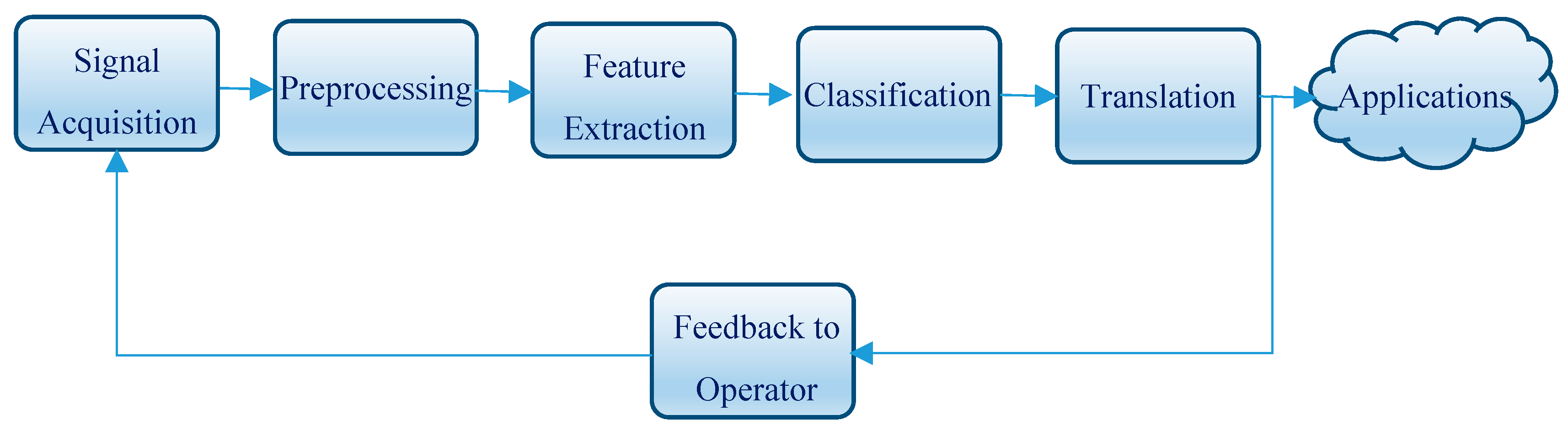
The most commonly used types of brain waveforms to develop EEG-based BCIs are P300, SSVEP, ErrP, ERD/ERS, and alpha brainwaves [11].
P300 is an event-related positive potential deflection which is caused by the reaction to a desired external stimulus of visual, auditory, or tactile modality. P300 waveforms are typically measured, with a latency of roughly 250 to 500 ms between stimulus and response, by using electrodes located over the parietal lobe of the scalp.
Steady state visually evoked potentials (SSVEP) are brain waveforms of exogenous type that are generated as responses to visual stimulation at specific frequencies ranging from 3.5 Hz to 75 Hz. Considering that SSVEP signals often have their highest values at medial occipital electrode sites, they are supposed to originate mostly from the primary visual cortex.
Event-related desynchronization and event-related synchronization (ERD/ERS) waves are endogenous brain signals, which are generated when performing mental tasks, such as motor imagery or mental arithmetic. They can be measured at different cortical locations.
Error-related potential (ErrP) waveforms are brain signals which are activated every time that a subject identifies the commitment of an error which has been made either by himself/herself or by another individual during various choice tasks. Waves of this kind can be captured by applying electrodes on various brain regions including the anterior cingulate cortex, anterior insula, inferior parietal lobe, and intraparietal sulcus, as well as other regions of the cortex, subcortex, and cerebellum.
Alpha brainwaves are brain signals which have their amplitude increased whenever the eyes of an individual are closed during wakeful relaxation. In contrast, the amplitude of alpha waveforms is diminished for the duration of sleepiness and sleep and also when having eyes opened while mental effort is performed. This phenomenon is usually referred to as alpha rhythm blocking. Alpha brain waveforms can be monitored by applying a number of electrodes on both sides of the posterior segments of the scalp where the occipital lobe, which is the center of visual processing activities in the brain, is positioned.

2.3. BCI Operation

The operation of a typical BCI system is based on the sequential execution of a number of procedures, which namely are signal acquisition, preprocessing, feature extraction, classification, translation, and feedback to operator [10,11], as shown in Figure 1.
In EEG-BCIs, signal acquisition is performed by using electrodes which are positioned along the scalp of the user. Normally, the settlement of electrodes on the scalp is performed in compliance to the International 10–20 system. According to this system, electrodes are located on the scalp at 10% and 20% of a measured distance from reference spots including nasion, inion, left, and right preauricular [10].
The pattern of this system is depicted in Figure 2, where odd numbers refer to the left side of the head, even numbers refer to the right side, A1 and A2 refer to the earlobes and ‘Fp’, ‘F’, ‘T’, ‘C’, ‘P’, and ‘O’ stand for the prefrontal, frontal, temporal, central, parietal, and occipital areas of the brain, correspondingly.
Preprocessing is the procedure which is carried out in order to reduce the noise from the signal and apply some filtering and other methods in order to remove artifacts which are caused by endogenous sources, such as motions of eyes, muscles, and heart, and exogenous sources, such as power-line coupling and impedance mismatch [12]. Preprocessing is usually performed by using low-pass, high-pass, band-pass, or notch filtering. However, the use of such filters may eliminate useful elements of EEG signals having the same frequency band as artifacts [13].
In feature extraction, specific features of the signals in time domain or/and frequency domain that can expressively differentiate specific classes are extracted and positioned into a feature vector in order to enable the classification phase which follows. Autoregressive (AR), Hjorth, and EEG signal power are commonly used feature extraction techniques [14].
During the classification phase, a properly built algorithm is used. This algorithm distinguishes between classes which correspond to various brain activity patterns by deciding to which of these classes every feature vector suits best. Neural networks (NNs) are widely used as classifiers in BCIs because they provide the ability to approximate nonlinear decision boundaries [15,16]. Alternatively, linear discriminant analysis (LDA), support vector machines (SVM), and statistical classifiers may be used [17]. The advantage of LDA is that it is a simple-to-use probabilistic approach based on Bayes’ Rule. On the other hand, NNs have the advantage of being able to approximate nonlinear decision boundaries. In cases where a small amount of training data is available, the use of SVM is a very good choice. Finally, statistical classifiers have the ability to represent the uncertainty that is inherent in brain signals.
During the translation phase the extracted signal features are converted into particular commands to the device(s) under control, through the use of dedicated translation algorithms. Specifically, these algorithms have the ability not only to adapt to the continuing variations of the signal features, but also to ensure that the complete device control range is covered by the specific signal features from the user.
Finally, in the feedback to operator phase, the final outcome of the overall operation of the BCI system is transferred back to the system operator, so that the performance of the system can be evaluated.

2.4. BCI-Based Robot Control

An EEG-based brain-controlled robot is a robot that uses an EEG-based BCI to receive control commands from its human operator. EEG-based brain-controlled mobile robots can support the movement of both elderly people and people who are severely disabled with destructive neuromuscular disorders, such as amyotrophic lateral sclerosis (ALS), multiple sclerosis (MS), or strokes.
There are two main classes of EEG-based brain-controlled assistive robots which namely are brain-controlled manipulators and brain-controlled mobile robots. Similarly, assistive mobile robots are classified in two categories according to their mode of operation [11].
The first category consists of assistive mobile robots which operate under direct BCI control. Robots of this kind are controlled exclusively via the commands that their users send to the robots controlled via BCI modules, without any additional assistance by robot intelligence elements. For this reason, they are less expensive and complex to develop and their users keep the absolute motion control.
On the other hand, the overall performance of these brain-controlled mobile robots mainly depends on the performance of the BCIs, which in many cases may have inadequate speed of response and accuracy. Furthermore, the demand for continuous production of motor control commands by the users may be extremely tiring for them.
The initial example of a robot of this kind was presented in [18] where the left and right turning movements of a robotic wheelchair were directly controlled by corresponding motion commands translated from user brain signals.
Similarly, in [19] a brain-controlled mobile robot was able to perform forward, left, and right motions by using a BCI based on motor imagery.
Moreover, in [20] the motion control of a wheelchair is performed via a BCI, which captures alpha brainwaves. Specifically, a set of icons corresponding to predefined commands are sequentially displayed on a screen and the user is able to select the desired command by closing his/her eyes as soon as its corresponding icon appears on the display unit.
The second category consists of assistive mobile robots which operate under shared control. In the robots of this category the control is performed by combining a BCI system along with an intelligent controller, such as an autonomous navigation system. Due to their enhanced intelligence, robots of this type are safer and less tiring for their users and more accurate in interpreting and executing their commands. On the other hand, their development is of higher cost and computational complexity.
A typical example of shared control in assistive mobile robots is proposed in [21]. In this system the operator, by using a SSVEP BCI system, has the ability to send commands in order to move a robotic wheelchair in four directions (forwards, backwards, left, and right), while an autonomous navigation system executes the delivered commands.
Similarly, in [22], by using a P300 BCI, the operator uses a list of predefined locations in order to select the desired location and then sends this selection to an autonomous navigation system, which guides a robotic wheelchair to the selected location. The limitation of the specific system is that it is able to be operated only in a known environment.
Likewise, in [23] shared control is used. Specifically, the combined use of a P300 BCI along with an autonomous navigation system is proposed in order to perform the motion control of a robotic wheelchair in an environment which is unknown. Moreover, the user has the ability to make the wheelchair turn either left or right by focusing correspondingly on one of two relative icons at a predefined visual display.
In [24] three mental tasks, which namely are the imagination of right or left hand movements and the generation of words beginning with the same random letter, were used in a BCI system applied to a robotic wheelchair. The system developed, which interacts with the user by using a PDA screen and speakers, is able to guide the robotic wheelchair both in known and unknown environments.

3. Materials and Methods

The research work carried out made use of the experimental equipment described in Section 3.1 and followed the procedure explained in Section 3.2.

3.1. Experimental Equipment

3.1.1. BCI Unit

The BCI device that was used, in order to capture the alpha brainwaves during the developed experimental procedure, is the OpenBCI Ganglion [25], which is shown in Figure 3. This board has 4 available input channels and samples data at 200 Hz.

3.1.2. Robotic Unit

The vehicle used for the execution of the experimental procedure is a crawler robot built on Dagu Rover 5 Chassis. A Raspberry Pi (model 3 B+) acts as the central processing unit for the robot. Communication between the robotic vehicle and the computer is achieved via a TCP/IP socket connection. As soon as the classifier determines the desired movement, a command is transmitted to the robot. A serial communication is established between the Raspberry Pi and an Arduino UNO microcontroller. Once a specified command is received by the Raspberry Pi, it is relayed to the microcontroller, which in turn uses a L298N H-Bridge driver module to control the motors of the robot. The experimental platform developed is illustrated in Figure 4.

3.2. Experimental Procedure

The performance of the system developed was experimentally evaluated through a series of tests. The main phases of the executed experimental procedure are as follows:

3.2.1. Signal Acquisition

The brain signals monitored are alpha waves, which, as mentioned above, is the prominent EEG wave pattern in awake adults while having eyes closed in the frequency range of 8–13 Hz. Generally, EEG-BCIs based on rhythms like alpha waveforms are less sensitive to artifacts than other types due to the fact that signal monitoring is limited in thin frequency bands. For this reason, high signal-to-noise ratio (SNR) is achieved [12].
Gold-plated electrodes were placed on the scalp of each one of the subjects that participated in the experimental procedure, according to the 10–20 system (displayed in Figure 2) at positions O1 and O2. The specific positions were chosen because, although alpha rhythms can be also generated in other parts of the brain, they are considered to exhibit greater amplitude in the posterior part of the brain, specifically at derivations O1 and O2 [26]. The reference electrode was placed on the left earlobe (A1), while the ground electrode was placed on the right earlobe (A2). In this way it is feasible to monitor alpha brainwaves.
As it was abovementioned, the amplitude of alpha brainwaves diminishes when subjects open their eyes. This is called alpha blocking phenomenon. By taking advantage of this phenomenon, subjects can form n-bit binary sequences by opening or closing their eyes in 2-second intervals. Each bit interval is designated by an acoustic cue.
Moreover, since this is a synchronous BCI, a button has to be pressed for the recording procedure to start. Increased alpha activity (eyes closed) corresponds to a binary ‘1’, while decreased activity (eyes open) corresponds to a binary ‘0’. As a proof of concept, 4-bit binary sequences were selected to demonstrate the effectiveness of this system. In total, 4 control signals were designated for 4 robotic movements as it can be seen in Table 1.

3.2.2. Preprocessing and Feature Extraction

In order to extract the desired alpha brainwaves from the EEG signals, filtering was applied. More specifically, a second order IIR notch filter, having a quality factor Q equal to 35, was applied in order to remove mains frequency (50 Hz).
Consequently, the signals were further filtered by using a Butterworth IIR bandpass filter with cutoff frequencies of 5 and 15 Hz. The maximum loss in the passband was found to be equal to 0.1 dB. Similarly, the minimum attenuation in the stopband was measured to be equal to 30 db. The SciPy Python library was used for the design and application of the filters.
A typical sample of the signal filtering process performed is indicatively depicted in Figure 5. Specifically, the top graph shows the unfiltered signal acquired from the O1 position on the scalp of a subject, which gives the command for a ‘left’ movement of the robotic vehicle. As aforementioned in Table 1, the corresponding binary sequence is 1100 and this is why the signal amplitude is higher during the first half of the signal duration and lower during the last half. The middle graph of Figure 5 illustrates the signal filtered via the use of the notch filter while the bottom graph shows the signal further filtered with the bandpass filter.
Since alpha wave blocking is the reduction of alpha waves’ amplitude, this change can be measured by transforming the EEG signal from the time domain to the frequency domain. This is achieved by computing the Discrete Fourier Transform (DFT) of the signal using the FFT algorithm. The resulting amplitudes for the alpha wave frequency range are then summed. This process is repeated 4 times for each individual control signal; this is because control signals comprise of 4 2-second recording intervals.
Min-Max normalization is used to scale the features in the range of [0, 1], which are then saved as a dataset. The resulting feature vector consists of 8 amplitude sums, 4 for each channel (O1, O2). A total of 256 feature vectors are contained within the dataset. A visualization of an example feature vector for the movement “left” is depicted in Figure 6, where there are 8 different values, 2 for each bit. It is fairly easy to distinguish each individual bit value; in this case ‘1100’.

3.2.3. Classification and Translation

The classifier utilized for this research is a Multilayer Perceptron (MLP) neural network. This selection was made because MLP neural networks constitute a very popular machine learning technique and there is an abundance of successful applications of MLP neural networks in EEG signal classification and BCI research [27,28].
The classifier built consists of an input layer with 8 neurons, since the feature vector contains 8 amplitude sums, 4 for each channel. Furthermore, there are 4 neurons in the output layer because there are 4 available classes (forward, reverse, left, and right). Moreover, there are 2 hidden layers, each one consisting of 100 neurons.
The number of hidden layers and neurons was determined by a trial and error procedure. Specifically, 1–3 hidden layers were considered. In addition, for each layer the number of neurons examined was 20–200 with a step of 20. In total, 175 different network configurations were considered. It was concluded that a2 hidden layers network with 100 neurons in each layer achieved the desired performance in terms of classification accuracy. A graphical depiction of the classifier built is illustrated in Figure 7.
The activation function for the hidden layers is the Rectified Linear Unit (ReLU). The advantages of ReLU include increased training speed and less suffering from the vanishing gradient problem [28]. The formula for ReLU is
R e L U ( x ) = m a x ( 0 , x ) .
As for the output layers, the sigmoid function was used, which is given by the formula:
σ ( x ) = 1 1 + e x ,
which bounds the output of each layer in the range of [0, 1]. This means that each neuron in the output layer produces probabilities of the input being one of the 4 commands. The command with the highest probability is selected.
The loss function used to measure the prediction error of the network during training is binary cross-entropy [29], which is widely used in binary classification problems. It is defined as
= 1 N n = 1 N [ y n · log y ^ n + ( 1 y n ) · log ( 1 y ^ n ) ] ,
where N is the number of samples, y n is the target output, and y ^ n is the predicted output. Finally, the optimization algorithm used to minimize the prediction error by adjusting the weight of each neuron is Adam, using the default hyperparameter values, as described in [30]. All models were trained in TensorFlow [31], using the Keras API [32].
In Figure 8 the neural network model training and validation loss is displayed. It can be distinguished that training could take place for a smaller number of epochs, since the loss is at an already acceptable value at around 25 epochs. The data used for validation is 40% of the total data.

4. Results and Discussion

The performance of the developed system was evaluated by using both offline and online data which were gathered through a series of experimental tests performed in which 12 healthy subjects participated.

4.1. Evaluation with Offline Data

For the offline evaluation, the system was tested by using prerecorded data gathered from the same subjects used for recording the training data. Specifically, a small testing dataset of 50 feature vectors representing different movements was used. The neural network classified all of the movements correctly.

4.2. Real-Time Evaluation

After evaluating the system on offline data, a real-time performance analysis was carried out by using six female and six male subjects aged 20 to 28, and two female and two male subjects aged 32 to 40 years. The specific subjects were different from those that were used for the classifier training and offline evaluation. For this purpose, an experimental process was carried out. The subjects were instructed to move the robot in the following order: forward, reverse, left, and right consecutively.
Each one of the 12 subjects was briefed shortly on how the BCI works and how to issue each movement command to the robot. A small number of trial runs were performed for the subjects to get acquainted with the procedure. In total, 40 experimental tests were carried out. The total number of commands issued was 480.
The results of the experimental procedure showed that lowest classification accuracy achieved among the subjects was 85% while the highest one was 97.5%. The overall accuracy for all commands was 92.1%. The confusion matrix for the total number of commands considered for classification is illustrated in Figure 9, where green diagonal cells correspond to commands that are successfully classified, the red cells correspond to incorrectly classified commands, the gray column on the right displays the precision and false recovery rate of the classifier, the gray row in the bottom expresses the recall and the false negative rate of the classifier, and the blue cell displays the overall accuracy.
Next, for analysis purposes, the experimental results were studied according to the gender and the age of the subjects that participated in the experimental procedure.
Specifically, the results were first grouped and analyzed separately for each gender. The confusion matrices for the female subjects and the male subjects are depicted in Figure 10 and Figure 11, respectively, where it is shown that the female subjects had a 1.6% higher classification accuracy compared to the male subjects (92.9% to 91.3%).
Next, the experimental results were grouped and analyzed according to the age of the subjects. The first group contains the results that refer to the eight subjects aged between 20 and 28 years and the second one the results derived by the four subjects aged between 32 and 40 years. The confusion matrices for the group 20–28 and the group 32–40 are depicted in Figure 12 and Figure 13, respectively, where it is shown that these two groups have almost the same precision accuracy (92.2% for the subjects aged 20 to 28 and 91.9% for the subjects aged 32 to 40).

4.3. Discussion

The overall accuracy of 92.1% achieved by the proposed approach is considered to be rather satisfactory, especially given the fact that this rate is the result of real-time evaluation. It is also important to note that different subjects than the ones used for training were employed for this evaluation, a fact which attests to the robustness of the proposed method.
Better insight to the results can be gained by looking at the confusion matrix for all issued subject commands. It can be seen that the proposed approach not only achieves a satisfactory overall success rate, but also provides good performance per each individual movement.
Further analysis of inter-class performance shows that in 8.3% of the cases a ‘reverse’ command was issued, it was misclassified as a ‘right’ command. Moreover, the command ‘left’ was misclassified as a ‘forward’ command at a rate of 5.8% and the ‘right’ command as a ‘reverse’ command at a rate of 7.5%. This can be attributed to the fact that there is a short time delay until alpha wave amplitudes increase or decrease upon eye closing or opening, respectively. Therefore, these amplitudes are calculated into the next bit value, which can lead to errors.
A good indicator of the probability of a command being classified wrongly is the Hamming distance between each command (Table 2). Therefore, the ‘forward’ and ‘reverse’ commands are more likely to be misinterpreted into ‘left’ or ‘right’ commands and vice versa. Representing each command with more than four bits would increase the Hamming distance and, as a result, the system accuracy, but it would increase the overall recording time since the duration of every bit recording is two seconds.
The categorization of the experimental results performed according to the age of the subjects showed that the deviation in the classification accuracy of the age groups is negligible, probably because of the relatively small age difference between the two groups.
However, female subjects in the experimental procedure followed, achieved relatively higher classification accuracy than the male ones. This can be attributed to the fact that women in general exhibit greater alpha amplitudes than men [33,34].
On the other hand, although the performance of the proposed system was found to be successful, it is true that all the participants during the experiments made in this research work were healthy. Therefore, in real life conditions the effectiveness of experimental systems, like the one developed in this research work, is questionable because it strongly depends on the health conditions of their users who are supposed not only to be disabled persons but also having disability of various levels.
Moreover, the achievement of successful performance of a mobile robot within the territory of a controlled laboratory environment does not guarantee its effectiveness in real-world applications where the conditions are mostly variable and fuzzy.
Furthermore, the BCI systems that are based on a single signal may not be applicable to all users. Therefore, hybrid schemes which make combined use of various types of brain signals can be a more complex yet even more effective alternative.

5. Conclusions and Future Research

The research work, presented in this paper, concerns the development of a control system which guides the motion of a mobile robot via a synchronous and endogenous EEG-based BCI, which uses the alpha brain waveforms of a human operator.
Experiments made, with the involvement of 12 subjects who had minimum training, proved that the system developed is able to guide the robotic vehicle under control in forward, left, backward, and right direction according to the eyes’ blinking of its human operator. The accuracy achieved ranges from 85% up to 97.5% among the subjects while the overall accuracy was found to be equal to 92.1% for all commands. Further analysis of the experimental data related with the classification accuracy between different genders and age groups showed that female subjects performed slightly better than male ones (92.9% to 91.3%, respectively), while there was just a trivial difference detected between subjects aged from 20 to 28 years and subjects aged from 32 to 40 years (92.2% to 91.9%, respectively).
Considering both the classification accuracy achieved, by applying real-time evaluation, and the robustness evinced by the fact that subjects involved during training were different than those during the experimental evaluation, it is concluded that the proposed method has the potential to be incorporated in applications such as the motion assistance to handicapped persons.
In the future, the conductors of this research work intend to experiment with hybrid BCIs where alpha brainwaves will be used along with brain signals of other type(s) such as P300 or SSVEP [35].
Moreover, task metrics, such as task completion time and path length traveled, and ergonomic metrics, such as mental workload of participants, can be additionally used for the accomplishment of multivariable evaluation of the performance of the system built [11].
Additionally, robot guidance can be assisted via additional sensors embedded into the robotic vehicle [36].
The detrimental effect of artifacts on EEG data can be removed by using modern algorithms that combine source decomposition with blind source separation and adaptive filtering [37].
Furthermore, enhanced performance can be achieved by applying advanced methods which have been proposed in order to add new knowledge to already learned models of robot semantic localization [38].

Author Contributions

All of the authors of this research article have extensively contributed to the work reported. Conceptualization, A.A., D.K., and N.K.; methodology, A.A. and D.K.; software, N.K.; validation, A.A., D.K., G.K., and N.K.; formal analysis, A.A., D.K., and N.K.; investigation, A.A., D.K., and N.K.; resources, D.K. and N.K.; data curation, A.A., D.K., and N.K.; writing—original draft preparation, A.A., D.K., and N.K.; writing—review and editing, A.A., D.K., G.K., and, N.K.; visualization, A.A. and N.K.; supervision, A.A., D.K., and G.K.

Funding

This research received no external funding.

Conflicts of Interest

The authors declare no conflict of interest.

References

  1. Dixon, A.M.; Allstot, E.G.; Gangopadhyay, D.; Allstot, D.J. Compressed sensing system considerations for ECG and EMG wireless biosensors. IEEE Trans. Biomed. Circuits Syst. 2012, 6, 156–166. [Google Scholar] [CrossRef]
  2. Perdiz, J.; Pires, G.; Nunes, U.J. Emotional state detection based on EMG and EOG biosignals: A short survey. In Proceedings of the 2017 IEEE 5th Portuguese Meeting on Bioengineering (ENBENG), Coimbra, Portugal, 16–18 February 2017; pp. 1–4. [Google Scholar]
  3. Valais, I.; Koulouras, G.; Fountos, G.; Michail, C.; Kandris, D.; Athinaios, S. Design and Construction of a Prototype ECG Simulator. EJST 2014, 9, 11–18. [Google Scholar]
  4. Subha, D.P.; Joseph, P.K.; Acharya, R.; Lim, C.M. EEG signal analysis: A survey. J. Med. Syst. 2010, 34, 195–212. [Google Scholar] [CrossRef] [PubMed]
  5. Wolpaw, J.R.; Birbaumer, N.; McFarland, D.J.; Pfurtscheller, G.; Vaughan, T.M. Brain–computer interfaces for communication and control. Clin. Neurophysiol. 2002, 113, 767–791. [Google Scholar] [CrossRef]
  6. Abdulkader, S.N.; Atia, A.; Mostafa, M.S.M. Brain computer interfacing: Applications and challenges. Egypt. Inform. J. 2015, 16, 213–230. [Google Scholar] [CrossRef]
  7. Katona, J.; Kovari, A. A Brain–Computer Interface Project Applied in Computer Engineering. IEEE Trans. Educ. 2016, 59, 319–326. [Google Scholar] [CrossRef]
  8. Katona, J.; Kovari, A. The Evaluation of BCI and PEBL-Based Attention Tests. Acta Polytechnica Hungarica 2018, 15, 225–249. [Google Scholar]
  9. Katona, J.; Kovari, A. Examining the learning efficiency by a brain-computer interface system. Acta Polytechnica Hungarica 2018, 15, 251–280. [Google Scholar]
  10. Nicolas-Alonso, L.F.; Gomez-Gil, J. Brain computer interfaces, a review. Sensors 2012, 12, 1211–1279. [Google Scholar] [CrossRef]
  11. Bi, L.; Fan, X.A.; Liu, Y. EEG-based brain-controlled mobile robots: A survey. IEEE Trans. Hum. Mach. Syst. 2013, 43, 161–176. [Google Scholar] [CrossRef]
  12. Minguillon, J.; Lopez-Gordo, M.A.; Pelayo, F. Trends in EEG-BCI for daily-life: Requirements for artifact removal. Biom. Signal Proces. Control 2017, 31, 407–418. [Google Scholar] [CrossRef]
  13. Padmavathi, R.; Ranganathan, V. A review on EEG based brain computer interface systems. Int. J. Emerg. Technol. Adv. Eng. 2014, 4, 683–696. [Google Scholar]
  14. Gandhi, V. Brain-Computer Interfacing for Assistive Robotics: Electroencephalograms, Recurrent Quantum Neural Networks and User-Centric Graphical Interfaces, 1st ed.; Academic Press: London, UK, 2014; pp. 29–30. [Google Scholar]
  15. Alexandridis, A.; Chondrodima, E.; Giannopoulos, N.; Sarimveis, H. A Fast and Efficient Method for Training Categorical Radial Basis Function Networks. IEEE Trans. Neural Netw. Learn. Syst. 2017, 28, 2831–2836. [Google Scholar] [CrossRef] [PubMed]
  16. Alexandridis, A.; Chondrodima, E.; Sarimveis, H. Radial Basis Function network training using a non-symmetric partition of the input space and Particle Swarm Optimization. IEEE Trans. Neural Netw. Learn. Syst. 2013, 24, 219–230. [Google Scholar] [CrossRef]
  17. Lotte, F.; Bougrain, L.; Cichocki, A.; Clerc, M.; Congedo, M.; Rakotomamonjy, A.; Yger, F. A review of classification algorithms for EEG-based brain-computer interfaces: A 10 year update. J. Neural Eng. 2018, 15, 1–55. [Google Scholar] [CrossRef]
  18. Tanaka, K.; Matsunaga, K.; Wang, H.O. Electroencephalogram based control of an electric wheelchair. IEEE Trans. Robot. 2005, 21, 762–766. [Google Scholar] [CrossRef]
  19. Choi, K.; Cichocki, A. Control of a wheelchair by motor imagery in real time. In Proceedings of the International Conference on Intelligent Data Engineering and Automated Learning, Daejeon, Korea, 2–5 November 2008; Springer: Berlin, Germany, 2008; pp. 330–337. [Google Scholar]
  20. Ferreira, A.; Silva, R.L.; Celeste, W.C.; Bastos, T.F.; Filho, M.S. Human–machine interface based on muscular and brain signals applied to a robotic wheelchair. J. Phys. Conf. Ser. 2007, 90, 1–8. [Google Scholar] [CrossRef]
  21. Mandel, C.; Luth, T.; Laue, T.; Röfer, T.; Graser, A.; Krieg-Bruckner, B. Navigating a smart wheelchair with a brain–computer interface interpreting steady-state visual evoked potentials. In Proceedings of the 2009 IEEE/RSJ International Conference on Intelligent Robots and Systems, St. Louis, MO, USA, 10–15 October 2009; pp. 1118–1125. [Google Scholar]
  22. Rebsamen, B.; Burdet, E.; Guan, C.; Zhang, H.; Teo, C.L.; Zeng, Q.; Ang, M.; Laugier, C. A brain controlled wheelchair based on P300 and path guidance. In Proceedings of the 1st IEEE/RAS-EMBS International Conference on Biomedical Robotics and Biomechatronics, Pisa, Italy, 20–22 February 2006; pp. 1001–1006. [Google Scholar]
  23. Iturrate, I.M.; Antelis, J.; Kubler, A.; Minguez, J. A noninvasive brain-actuated wheelchair based on a p300 neurophysiological protocol and automated navigation. IEEE Trans. Robot. 2009, 25, 614–627. [Google Scholar] [CrossRef]
  24. Benevides, A.B.; Bastos, T.F.; Filho, M.S. Proposal of brain–computer interface architecture to command a robotic wheelchair. In Proceedings of the IEEE International Symposium in Industrial Electronics, Gdansk, Poland, 27–30 June 2011; pp. 2249–2254. [Google Scholar]
  25. Samson, V.R.R.; Kitti, B.P.; Kumar, S.P.; Babu, D.S.; Monica, C. Electroencephalogram-Based OpenBCI Devices for Disabled People. In Proceedings of the 2nd International Conference on Micro-Electronics, Electromagnetics and Telecommunications, Visakhapatnam, India, 6–7 January 2017; pp. 229–238. [Google Scholar]
  26. Olejarczyk, E.; Bogucki, P.; Sobieszek, A. The EEG split α peak: Phenomenological origins and methodological aspects of detection and evaluation. Front. Neurosc. 2017, 11, 506. [Google Scholar] [CrossRef]
  27. Jana, G.C.; Swetapadma, A.; Pattnaik, P.K. Enhancing the performance of motor imagery classification to design a robust brain computer interface using feed forward back-propagation neural network. Ain Shams Eng. J. 2018, 9, 2871–2878. [Google Scholar] [CrossRef]
  28. Subasi, A.; Erçelebi, E. Classification of EEG signals using neural network and logistic regression. Comput. Methods Programs Biomed. 2005, 78, 87–99. [Google Scholar] [CrossRef] [PubMed]
  29. De Boer, P.T.; Kroese, D.P.; Mannor, S.; Rubinstein, R.Y. A tutorial on the cross-entropy method. Ann. Oper. Res. 2005, 134, 19–67. [Google Scholar] [CrossRef]
  30. Kingma, D.P.; Ba, J. Adam: A Method for Stochastic Optimization. arXiv 2014, arXiv:1412.6980. [Google Scholar]
  31. Abadi, M.; Barham, P.; Chen, J.; Chen, Z.; Davis, A.; Dean, J.; Devin, M.; Ghemawat, S.; Irving, G.; Isard, M.; et al. TensorFlow: A system for large-scale machine learning. In Proceedings of the 12th USENIX Symposium on Operating Systems Design and Implementation (OSDI 16), Savannah, GA, USA, 2–4 November 2016; pp. 265–283. [Google Scholar]
  32. Chollet, F. Keras: The python deep learning library. Astrophys. Source Code Libr. 2018. Available online: https://keras.io/k (accessed on 19 November 2019).
  33. Wada, Y.; Takizawa, Y.; Zheng-Yan, J.; Yamaguchi, N. Gender differences in quantitative EEG at rest and during photic stimulation in normal young adults. Clin. Electroencephalogr. 1994, 25, 81–85. [Google Scholar] [CrossRef] [PubMed]
  34. Corsi-Cabrera, M.; Ramos, J.; Guevara, M.A.; Arce, C.; Gutierrez, S. Gender Differences m in the Eeg During Cognitive Activity. Int. J. Neurosci. 1993, 72, 257–264. [Google Scholar] [CrossRef]
  35. Amiri, S.; Fazel-Rezai, R.; Asadpour, V. A review of hybrid brain-computer interface systems. Adv. Hum. Comput. Interact. 2013, 2013, 1–12. [Google Scholar] [CrossRef]
  36. Zantalis, F.; Koulouras, G.; Karabetsos, S.; Kandris, D. A Review of Machine Learning and IoT in Smart Transportation. Future Internet 2019, 11, 94. [Google Scholar] [CrossRef]
  37. Jafarifarmand, A.; Badamchizadeh, M.A. EEG Artifacts Handling in a Real Practical Brain-Computer Interface Controlled Vehicle. IEEE Trans. Neural Syst. Rehabilit. Eng. 2019, 27, 2000–2008. [Google Scholar] [CrossRef]
  38. Cruz, E.; Rangel, J.C.; Gomez-Donoso, F.; Bauer, Z.; Cazorla, M.; García-Rodríguez, J. Finding the place: How to train and use convolutional neural networks for a dynamically learning robot. In Proceedings of the 2018 International Joint Conference on Neural Networks (IJCNN), Rio de Janeiro, Brazil, 8–13 July 2018; pp. 1–8. [Google Scholar]
Figure 1. Block diagram representing the processes performed in a typical Brain–Computer Interface.
Electronics 08 01387 g001
Figure 2. Top view of the international 10–20 electrode placement system on a human scalp.
Electronics 08 01387 g002
Figure 3. Overview of the Open Brain–Computer Interface (BCI) Ganglion unit used.
Electronics 08 01387 g003
Figure 4. Overview of the robotic unit used.
Electronics 08 01387 g004
Figure 5. From top to bottom: Unfiltered electroencephalography (EEG) signal, EEG signal after being filtered with a 50 Hz notch filter, and final EEG signal with additional 5–15 Hz bandpass filter application.
Electronics 08 01387 g005
Figure 6. Bar chart showing the normalized sum of the FFT amplitudes for each EEG channel.
Electronics 08 01387 g006
Figure 7. Structure of the neural network built.
Electronics 08 01387 g007
Figure 8. Training and validation model loss.
Electronics 08 01387 g008
Figure 9. Confusion matrix for all issued subject commands.
Electronics 08 01387 g009
Figure 10. Confusion matrix for female subjects.
Electronics 08 01387 g010
Figure 11. Confusion matrix for male subjects.
Electronics 08 01387 g011
Figure 12. Confusion matrix for ages 20 to 28.
Electronics 08 01387 g012
Figure 13. Confusion matrix for ages 32 to 40.
Electronics 08 01387 g013
Table 1. Binary sequences with corresponding robotic movements.
Binary SequenceRobotic Movement
‘1010’Forward
‘0101’Reverse
‘1100’Left
‘0011’Right
Table 2. Hamming distances between robot commands.
Command ‘1010’‘0101’‘1100’‘0011’
Forward‘1010’0422
Reverse‘0101’4022
Left‘1100’2204
Right‘0011’2240

