Article

Dynamic Improvement with a Feedforward Control Strategy of Bidirectional DC-DC Converter for Battery Charging and Discharging

1
Institute of Electric Drives and Control Systems, Shanghai Maritime University, Shanghai 201306, China
2
Shanghai Qianli Electric Technology Co., Ltd., Shanghai 201803, China
*
Author to whom correspondence should be addressed.
Submission received: 28 September 2020 / Revised: 13 October 2020 / Accepted: 18 October 2020 / Published: 21 October 2020
(This article belongs to the Section Power Electronics)

Abstract

:
With the increasing importance of power accumulator batteries in electric vehicles, the accurate characteristics of power accumulator batteries have an important role. In order to evaluate the power accumulator battery, battery charging and discharging is indispensable. In this article, a H-bridge bidirectional DC-DC converter is presented which can charge and discharge the battery with different voltage levels and one of the merits of this topology is that a wide output voltage range can be easily achieved. In the control part, a proportional-integral (PI) control strategy is adopted to ensure a stable and reliable operation of the converter. Furthermore, compared with the PI control strategy, a duty ratio feedforward control is utilized to obtain the rapid current dynamic response. In this article, firstly, the system configuration for battery charging and discharging is introduced, then the operating principles and mathematical model of the DC-DC converter are analyzed and derived. Secondly, for bidirectional DC-DC converters, the PI control method and duty ratio feedforward control method are put forward and designed. Finally, the simulation model is established based on PSIM software and the experiment platform is also built in lab. The results of the simulation and experiment research show that the H-bridge bidirectional DC-DC converter can operate reliably and stably during the charging, discharging and power flow reverse modes. In addition, the dynamic response of the charging and discharging current can also be further improved by introducing the duty ratio feedforward control method.

1. Introduction

In recent times, bidirectional DC-DC converters and power accumulator batteries have rapidly enlarged their application areas, such as (i) microgrid systems [1,2,3,4,5], (ii) energy storage systems [6,7], and (iii) electric vehicle (EV) systems [8,9,10]. In most applications, batteries with high energy density are required to provide stable and constant power. In order to evaluate the related parameters and performance of batteries, charging and discharging the battery plays a leading role. Therefore, power conversion systems for battery charging, discharging [11] and management [12] are the prime concern of researchers and receive more and more attention.
In conventional power accumulator battery charging and discharging processes, a DC power supply can be obtained from the grid by rectifiers and charges the battery through an isolated bidirectional DC-DC converter during the charging mode. Then, the energy of the battery is usually released through the resistance during the discharging mode. A major problem of this equipment lies in the energy released by the battery not being able to be directly injected back into the grid to avoid a great waste of energy when working in the discharging mode. To solve this problem, the focus is usually on the bidirectional AC-DC converter. A bidirectional AC-DC converter [13,14] is one of the indispensable parts in battery charging and discharging processes, which can realize bidirectional power flow between the grid and DC bus. During the power accumulator battery charging and discharging process, due to the fixed output voltage of bidirectional AC-DC converters, the battery of different voltage levels cannot be directly connected to the bidirectional AC-DC converter without any intermediate power converter. Thus, in practice, a bidirectional AC-DC converter followed by a bidirectional DC-DC converter is much more popular, as illustrated in [15]. The AC-DC converter manages the power flow between the DC bus and grid, and the DC-DC converter controls the power flow between the DC bus and the battery. In the literature [16,17,18], a series of bidirectional DC-DC converter topologies are discussed and analyzed. The bidirectional DC-DC converters can be divided into non-isolated [19] and isolated [20,21] bidirectional DC-DC converters. In view of the advantage of non-isolated DC-DC converters, the numbers of components are fewer and power-stage efficiency is high because of the lack of high-frequency transformers. Due to the bidirectional AC-DC converter being isolated from the grid, a non-isolated bidirectional DC-DC converter is usually selected as the alternate for battery charging and discharging.
As the most commonly used non-isolated bidirectional DC-DC converter, the bidirectional half-bridge DC-DC converter [22] is popular. One of the main advantages of this topology lays in the simple structure, only a half-bridge Insulated Gate Bipolar Transistor (IGBT) module is needed. For the purpose of further reducing the current ripple and decreasing the size of the filter efficiently, in [23] and [24] multi-phase interleaved bidirectional half-bridge DC-DC converters are put forward. During the charging and discharging process, various kinds of control strategies have been studied by researchers recently. In [25], an effective control method based on the sliding mode control is proposed to ensure a reliable output voltage regulation and get rid of the influence of DC bus voltage fluctuation. In [26], the enumeration-based model predictive control method is presented to achieve the regulation of the output voltage to its reference without a subsequent current control loop. During sudden transient events, reference [27] proposed an intelligent frequency control strategy to improve dynamic performance as compared to conventional PI controllers. However, one of the drawbacks of this converter is that a wide output voltage range cannot be achieved with a fixed DC bus voltage to charge and discharge the battery at different voltage levels. It is important to note that the main reason for such a problem is the limitation of the boost ratio due to the limitation of the maximum and minimum duty ratio.
To solve the aforementioned problems, the literature [28] presents a two-stage DC-DC converter, which is composed of a H-bridge converter and two-phase interleaved buck converter. It can obtain a wide output voltage range, but the efficiency is limited. Unlike the conventional configuration, the output voltage of the bidirectional H-bridge DC-DC converter is the difference of the output voltage of two half-bridge DC-DC converters. Therefore, the bidirectional H-bridge DC-DC converter can obtain a low output voltage without the limitation of the duty ratio and then get a wide output voltage range with a fixed DC bus voltage. In addition, double-frequency pulse width modulation (PWM) [29] is employed to further improve output waveform and reduce the current ripple. Therefore, in this article, the H-bridge converter illustrated in [28] is employed to realize the charge and discharge batteries of different voltage levels. In the control part, PI control is the most commonly used control method, it can achieve an accurate and stable output. However, in order to further improve the dynamic and anti-interference performance of the converter, a feedforward control method is introduced in this article.
The main contribution of this article is that a wide range output voltage for different battery voltage levels can be obtained by the bidirectional H-bridge DC-DC converter and the duty ratio feedforward control strategy is applied to improve the dynamic response of the output current. In the rest of the paper, the system configuration, circuit description and operational principles are presented in Section 2. The model of bidirectional H-bridge DC-DC converter is built and discussed in Section 3. Then, in Section 4, the controller design and analysis are illustrated. Results of the simulation and experiment are illustrated in Section 5. Finally, the conclusion of the paper is drawn in Section 6.

2. Circuit Description and Operational Principles

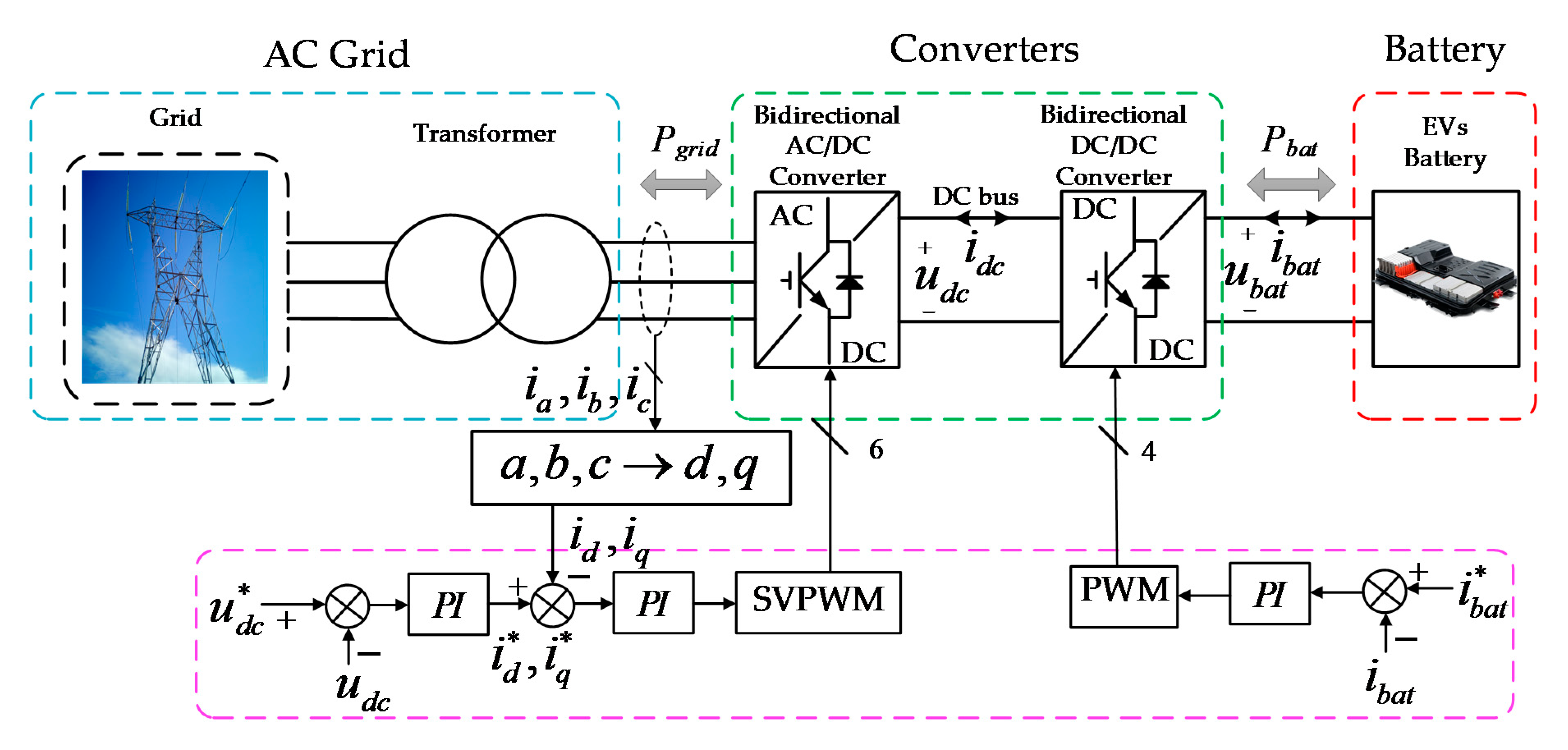
2.1. System Structure

The structure of the battery charging and discharging system is shown in Figure 1; the system is made up of three parts, an AC grid, converters, and battery. The AC voltage of converters is obtained from AC supplies through a transformer. Converters are composed of a bidirectional AC-DC converter and bidirectional DC-DC converter. The AC-DC converter transforms AC to DC and the bidirectional DC-DC converter manages the power flow between the DC bus and the battery [15].

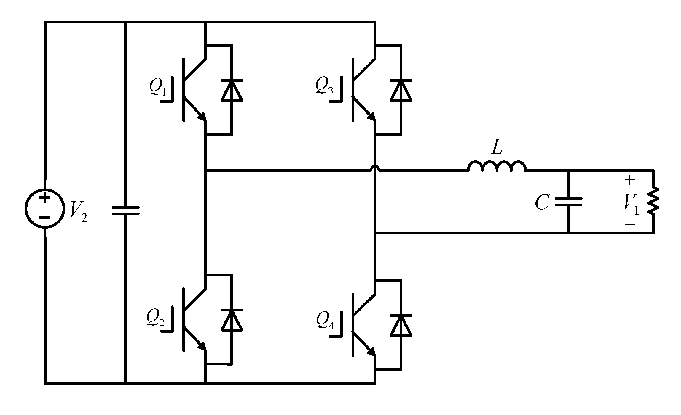
2.2. Circuit Description

The H-bridge bidirectional DC-DC converter adopted in the system is shown in Figure 2 as illustrated in [28], which can be seen as the two bidirectional half-bridge DC-DC converters made; the input ports of the two converters are parallel and the output ports are connected in reverse series. An H-bridge bidirectional DC-DC converter has the following advantages over half-bridge bidirectional DC-DC converters when charging and discharging battery: (i) wide output voltage range can be achieved with fixed DC bus voltage; (ii) smaller current ripple can be obtained to prolong the life of battery; (iii) working in four quadrants.

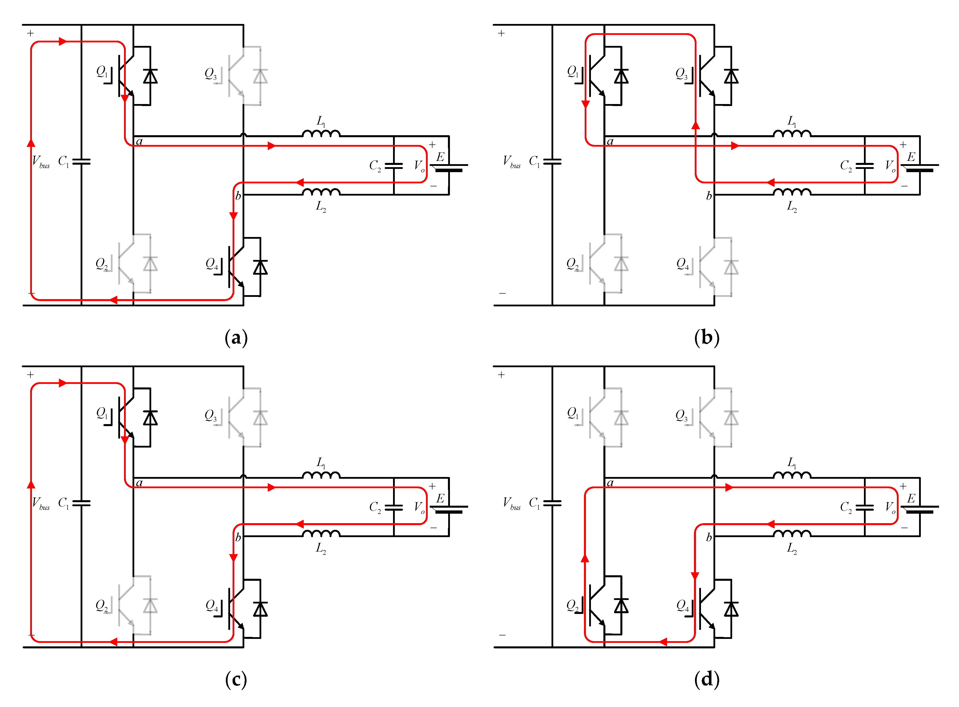
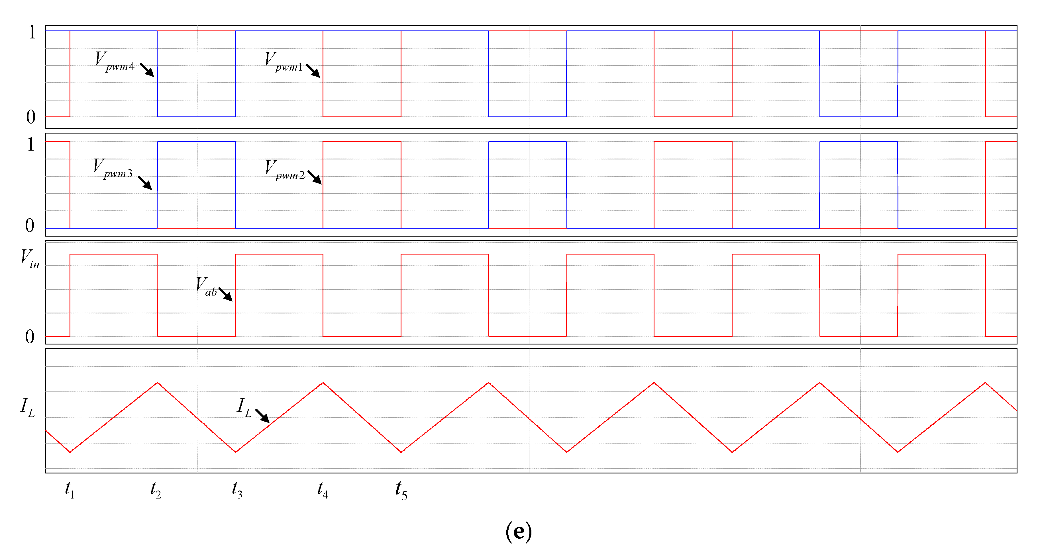
2.3. Operational Principles

During the charging mode, the buck operation is achieved by the DC bus which delivers the energy into the battery. To further reduce the current ripple and get the wide output voltage range, double-frequency pulse width modulation (PWM) is adopted [29]. In this mode, the DC bus voltage is 700 V and the inductance current is 100 A. Related waveforms and equivalent circuits of each operating mode under buck operation power flow are shown in Figure 3 and are analyzed and discussed.
Mode I ( t 1 ~ t 2 ): During the t 1 to t 2 period, Q 1 and Q 4 are turned on, and Q 2 and Q 3 are turned off. The DC bus delivers the energy into the battery. The current flows from the positive of the DC bus to the negative of the DC bus by Q 1 , L 1 , E , L 2 and Q 4 . Related waveforms are shown in Figure 3e. At this stage, the inductance current rises linearly and V a b is the DC bus.
Mode II ( t 2 ~ t 3 ): During the t 2 to t 3 period, Q 1 is continuously on while Q 4 is turned off, and the current of the inductance cannot change instantly; therefore, the current still flows into the battery, and it flows by L 1 , E , L 2 , D 3 , Q 1 and D 3 is the body diode of Q 3 . At this stage, the inductance current decreases linearly and V a b is zero.
Mode III ( t 3 ~ t 4 ): During the t 3 to t 4 period, Q 1 is continuously on while Q 4 is turned on, the operating principle is the same as Mode I; thus, the waveforms and power flow are also the same.
Mode IV ( t 4 ~ t 5 ): During the t 4 to t 5 period, Q 4 is still on while Q 1 is turned off. At this time, operating principles are similar to Mode II due to the current of the inductance not being able to change instantly. Therefore, the direction of the current is still towards to the battery and flows by L 1 , E , L 2 , Q 4 and D 2 , and D 2 is the body diode of Q 2 .
As can be inferred from previous operating modes and waveforms, during one switching period, the energy is always transferred into the battery and the ripple frequency of the inductance current is twice that of the switching frequency, which can illustrate that the equivalent switching frequency is twice that of the switching frequency during the charging and discharging process by double-frequency PWM.
Similarly, during the discharging mode, the DC bus voltage is also 700 V and the inductance current is also 100 A, and the boost operation is achieved by the battery and delivers the released energy into the DC bus. The power flow and related waveforms of each operating mode under boost operation are shown in Figure 4 and are analyzed and described.
Mode I ( t 1 ~ t 2 ): During the t 1 to t 2 period, Q 2 and Q 4 are turned on, and Q 1 and Q 3 are turned off. The battery charges the inductance and energy can be stored in the inductance resulting in the inductance current rising slowly in the negative direction. The current flows from the positive of the battery to the negative of the battery by E , L 1 , Q 2 , Q 4 , L 2 . Related waveforms are shown in Figure 4e. At this stage, it can be inferred that inductance current rises linearly in the negative direction and V a b is zero.
Mode II ( t 2 ~ t 3 ): During the t 2 to t 3 period, Q 4 is continuously on while Q 2 is turned off and the current of the inductance cannot change instantly; therefore, the stored energy in the inductance cannot be released immediately, and current can only flow into the DC bus by E , L 1 , Q 1 , Q 4 , L 2 . At this stage, the inductance current decreases linearly and V a b is the DC bus.
Mode III ( t 3 ~ t 4 ): During the t 3 to t 4 period, Q 1 is continuously on while Q 3 is turned on, the operating principle is the same as Mode I; thus, the waveforms are also the same as Mode I and the current flows from E , L 1 , Q 1 , Q 3 and L 2 .
Mode IV ( t 4 ~ t 5 ): During the t 4 to t 5 period, Q 1 is still on while Q 4 is turned on. At this time, operating principles are similar to Mode II due to the current of the inductance not being able to change instantly. Therefore, the direction of the current is still towards to the DC bus and flows by E , L 1 , Q 1 , Q 4 and L 2 .
According to a previous analysis, during one switching period, the energy is always injected into the DC bus from the battery. This is the same as the buck mode in that the equivalent frequency is also twice the switching frequency in one switching period during the discharging mode.
For the purpose of obtaining the relationship of the output and input, only the buck mode is taken as an example for a detailed analysis. From previous analysis, four operating modes are illustrated. In four operating modes, the inductance voltage for this subinterval is given by:
{ v L = V b u s V o v L = V o v L = V b u s V o v L = V o
According to the volt-seconds of the inductance, during one switching period, Equation (2) can be derived:
0 T s v L ( t ) d t = ( V b u s V o ) ( D 1 2 ) T s + ( V o ) ( 1 D ) T s + ( V b u s V o ) ( D 1 2 ) T s + ( V o ) ( 1 D ) T s
Equating this formula to zero and simplifying, it can be calculated that:
( V b u s V o ) ( D 1 2 ) T s + ( V o ) ( 1 D ) T s + ( V b u s V o ) ( D 1 2 ) T s + ( V o ) ( 1 D ) T s = 0
Solution for V o , the relationship between the output and input is that:
V o = ( 2 D 1 ) V b u s

3. Model of the Bidirectional DC-DC Converter

Without a thorough theoretical analysis of the proposed converter, it is quite difficult to achieve good designs of the controller. In this section, according to the four modes of the bidirectional DC-DC converter, a mathematical model of bidirectional DC-DC converter a is set up based on the stated-space averaging method [30]. Then, with the mathematical model, the controller of the converter is designed.
In the buck mode, for the convenience of the study, Figure 5 shows the simplified model. From Figure 5, the DC bus voltage is defined as V 2 , output voltage is defined as V 1 and the load is R . According to previous analysis, the inductance equations of state during buck mode are as follows:
During one switching period, voltage of the inductance can be described as follows in four modes:
{ v L ( t ) = L d i L ( t ) d t = v 2 ( t ) v 1 ( t ) v L ( t ) = L d i L ( t ) d t = v 1 ( t ) v L ( t ) = L d i L ( t ) d t = v 2 ( t ) v 1 ( t ) v L ( t ) = L d i L ( t ) d t = v 1 ( t )
During one switching period, v 2 ( t ) and v 1 ( t ) are continuous and have a small change, therefore v 2 ( t ) and v 1 ( t ) can be replaced by their low-frequency averaged values, v 2 ( t ) = v 2 ( t ) T S , v 1 ( t ) = v 1 ( t ) T S , according to Equation (5). The voltage of the inductance in one switching period is presented as follows:
v L ( t ) T S = 1 T S [ 0 ( d 1 2 ) T S v L ( t ) d t + ( d 1 2 ) T S 1 2 T S v L ( t ) d t + 1 2 T S d T S v L ( t ) d t + d T S T S v L ( t ) d t ] = L d i L ( t ) T S d t = ( 2 d 1 ) v 2 ( t ) T S v 1 ( t ) T S
With Kirchhoff’s Current Law (KCL), during one period, the average current of the capacitance is described as:
i C ( t ) T S = C d v 1 ( t ) T S d t = i L ( t ) T S v 1 ( t ) T S R
When the converter is working in a steady-state or quiescent duty ratio d = D , V 2 = v 2 ( t ) T S , and V 1 = v 1 ( t ) T S , I L = i L ( t ) T S .
With voltage-second balance and capacitor charge balance, from Equations (6) and (7) it can be inferred that:
{ V 1 = ( 2 D 1 ) V 2 V 1 R = I L
Introducing the disturbance in the given quiescent values such that:
{ v 2 ( t ) T S = V 2 + v ^ 2 ( t ) d = D + d ^
As a response, the voltage and current of the converter can be expressed as:
{ v 1 ( t ) T S = V 1 + v ^ 1 ( t ) i L 1 ( t ) T S = I L 1 + i ^ L 1 ( t )
According to previous equations, the inductance and capacitance equations can be obtained as follows by introducing disturbance [30]:
{ L d ( I L + i ^ L ( t ) ) d t = ( 2 ( D + d ^ ) 1 ) ( V 2 + v ^ 2 ( t ) ) ( V 1 + v ^ 1 ( t ) ) C d ( V 1 + v ^ 1 ( t ) ) d t = ( I L + i ^ L ( t ) ) ( V 1 + v 1 ( t ) R )
Due to I L being a constant DC term, the derivative of I L is zero. In order to derive the small-signal AC model, second-order terms and DC terms are desired to be neglected and removed, then it can be obtained:
{ L d i ^ L ( t ) d t = 2 V 2 d ^ + ( 2 D 1 ) v ^ 2 ( t ) v 1 ( t ) C d v ^ 1 ( t ) d t = i ^ L ( t ) v ^ 1 ( t ) R
According to Equation (12), the small-signal AC equivalent circuit is built as illustrated in Figure 6 based on ideal transformers, voltage source and current source.
Then, a Laplace transformation is performed on the combined equations and it can be described as follows:
{ L s i ^ L ( s ) = 2 V 2 d ^ + ( 2 D 1 ) v ^ 2 ( s ) v ^ 1 ( s ) C s v ^ 1 ( s ) = i L ( s ) v ^ 1 ( s ) R
By simplifying Equation (13), the open-loop transfer function of the converter can be inferred as follows:
G i d ( s ) = i ^ L ( s ) d ^ ( s ) | v ^ 2 ( s ) = 0 = 2 V 2 ( s C + 1 R ) L C s 2 + L R s + 1
Similarly, in the boost mode, the transfer function can also be obtained as follows:
G i d ( s ) = i ^ L ( s ) d ^ ( s ) | v ^ 1 ( s ) = 0 = V 2 ( s C + 2 R ) L C s 2 + L R s + 2 D 2

4. Controller Design of Bidirectional DC-DC Converter

For the battery charging and discharging process, there are many charging and discharging methods. Generally, constant current (CC) charging and constant voltage (CV) charging constitute the charger system [10]. Initially, when the battery voltage is relatively low, the converter will charge the battery in CC mode, and at this time the battery voltage will gradually increase. When the battery voltage reaches a certain value, the converter will switch to CV charging mode to charge the battery. After a while, the charge process will be finished when the battery capacity reaches a certain value. In the discharging process, a CC discharge mode is usually adopted. At this time, the converter discharges the battery with a constant current and the battery voltage gradually decreases; however, to avoid battery damage, the decline voltage should be set up. When the battery voltage reaches the lower limit, the converter should stop the discharging process.
In the article, during the charging and discharging process, only the CC mode is adopted, because most of the time the system will work in this mode. Therefore, only a current closed-loop control strategy is employed according to previous illustration and it is aimed at providing an accurate current through stable operations during the charging and discharging process. The block diagram of the current closed-loop control strategy for a bidirectional DC-DC converter is shown in Figure 7. In Figure 7, N is the disturbance and V is the output voltage before the inductance as V a b in Figure 3.
In this control diagram, the current closed-loop control is aimed at maintaining the average current i L to its current reference i r e f during the battery charging and discharging process with a constant current. In Figure 7, T s is the switching period of current loop. K i P and K i L are the proportional and integration coefficient of PI regulator, respectively; K p w m is the equivalent gain of PWM. In this paper, K p w m is equal to 1 due to PWM modulation being applied [31]. Ignoring the disturbance, the simplified block diagram of the current closed-loop control is shown in Figure 8.
In this block diagram, τ i can be expressed as K i P / K i I , and the current open-loop transfer function is obtained as follows:
G o i ( s ) = K i P K p w m R τ i s ( 1.5 T s s + 1 )
When ξ = 0.707 , it can be derived that:
K i P K p w m R τ i 1.5 T s = 1 2
Considering Equations (16) and (17), the K i P and K i I can be calculated, respectively, as Equation (18):
{ K i P = R τ i 3 T s K p w m K i I = R 3 T s K p w m
From Figure 8, the current closed-loop transfer function can be derived, which can be described as:
G c i ( s ) = 1 1 + R τ i K i P K p w m s + 1.5 T s R τ i K i P K p w m s 2
In Equation (19), since the switching frequency is high enough, then T s is small enough. Therefore, the coefficient of s 2 can be ignored and the current closed-loop transfer function can be expressed as:
G c i ( s ) 1 1 + R τ i K i P K p w m s
Comparing Equations (20) and (21), the G c i ( s ) can be simplified to:
G c i ( s ) = 1 1 + 3 T s s
From Equation (21), the current closed-loop can be equivalent to a first-order inertial element, where 3 T s is inertial time constant [31]. Obviously, when the switching frequency of the system is high enough, a fast dynamic response of the system can be obtained. According to Equation (18) and Table 1, the values of K i P and K i I are 5.3 and 166, respectively. Then, Figure 9 shows the Bode diagram of the system with the PI parameter.
During the charging and discharging process, for the purpose of improving the dynamic response of the converter and to reduce the effect of the output voltage and input voltage disturbance, the duty ratio feedforward control method is put forward [32].
In previous discussions, the relationship of input voltage and output voltage is V o = D V b u s , and D is the duty cycle of the converter in steady-state. From this equation, it can be obtained that the duty cycle of the converter only depends on the input voltage and output voltage and it has nothing to do with the current in a steady state. Therefore, by controlling the duty ratio of the converter in this equation, the disturbance of input voltage and output voltage will be rejected [32]. Different from feedback control, by introducing a feedforward control strategy, the dynamic performance of the charging and discharging current will be also improved. The reason for this phenomenon is that when the input voltage and output voltage have changed, the duty ratio of the converter will be also change immediately due to D ¯ = V o V i n and thus will be help to improve the dynamic performance of the current. So, in order to achieve fast current tracking, the duty ratio feedforward control method is adopted and the actual duty ratio of the control system is illustrated as:
D = D ¯ + D f e e d b a c k = V o V i n + k p ( i r e f i L f ) + k i ( i r e f i L f ) d t
The final control block diagram by introducing a feedforward control strategy diagram is shown in Figure 10.

5. Simulation and Experiment Results

5.1. Simulation Study

In this section, to validate the effectiveness of the feedforward and PI control strategy, a model of a H-bridge bidirectional DC-DC converter is established in a PSIM simulation environment. The main circuit of Figure 2 is taken, and the parameters are shown in Table 1. A resistance was adopted to replace the battery. The simulation studies are conducted for the buck and boost modes to verify the validity of the purposing controller.
In the following waveforms, I L P I is the inductance current with PI control and I L F F C is the inductance current with duty ratio feedforward control. Similarly, I o P I and I o F F C represent the output current with PI control and duty ratio feedforward control, respectively.
Firstly, during the charging mode, Figure 11a shows the start-up output current and inductance current with different control methods. From the waveform, the output current can reach the reference +100 A precisely without overshooting, and the response time of the output current with PI control is about 10.68 ms. By introducing the duty ratio feedforward control, the response time can be shortened to 8.19 ms accordingly. Similarly, the dynamic response of the converter during the turn-off process is shown in Figure 11b; when t equal to 0.05 s, the converter is shutdown, and the response time is about 10.65 ms with PI control. Then, with duty ratio feedforward control, the response time can be reduced to 8.20 ms.
Secondly, during the discharging mode, Figure 12 shows the output current and inductance current waveforms with PI control and duty ratio feedforward control during the start-up and turn-off processes. It can be inferred from Figure 12a,b that the output current can also reach the reference −100 A precisely without overshooting by different control strategies. Moreover, through PI control, the dynamic response time of the start-up and turn-off processes are both 10.65 ms. Then, through the duty ratio feedforward control, the response time of the output current is shortened to 8.19 ms during the start-up and turn-off processes.
Thirdly, from Figure 13a, the output current is positive before the power flow reverses, which suggests that the bidirectional DC-DC converter works in the charging mode. When the power flow reverse at t is equal to 0.05 s, the converter is working in the discharging mode and after 14.65 ms the current reaches the reference −100 A by PI control. Then, obviously, by the feedforward controller, the response time of the power flow reverse can be shortened to 11.42 ms. Similarly, from the discharging mode to charging mode, it takes about 14.66 and 11.42 ms with PI control and feedforward control accordingly.
At last, Figure 14 shows the inductance current and output current in steady-state. From the waveform, it can be observed that the ripple frequency of the inductance current of the converter is about 10 kHz, and it is twice the switching frequency. It is indicated that the equivalent switching frequency is increased by double-frequency PWM. In addition, the ripple current of the inductance is about 1 A when the output current is 100 A in steady-state.

5.2. Experiment Results

In this study, to validate the converter design, a 450-kW H-bridge bidirectional DC-DC converter platform is established as shown in Figure 15. The input voltage was provided by the output voltage of bidirectional AC-DC converter and battery was replaced by the resistance. Related parameters of the converter are shown in Table 1. TMS320F28335 DSP and XC6SLX9 FPGA were selected as the controller to sample, calculate and control. The IGBT is Infineon FF1000R17IE4, and the driver of IGBT is Firstack PM0538. The results are presented in Figure 16.
For the purpose of illustrating the advantages of the proposed duty ratio feedforward control strategy, the output current dynamic performance of the duty ratio feedforward and PI control strategy are compared in Figure 16. As similar to the simulation, I L P I is the inductance current with the PI control and I L F F C is the inductance current with the duty ratio feedforward control. I o P I and I o F F C represent the output current with the PI control and duty ratio feedforward control methods, respectively. In Figure 16, the reference is set up as 100 A under the charging and discharging mode, and it can be observed that both with PI control and duty ratio feedforward controls the output current can obtain accurate tracking of the reference during charging, discharging and power flow reverse processes. However, it can be observed that the dynamic performance of the output current and inductance current is obviously rapider than the PI control during the charging, discharging and power flow reverse processes with duty ratio feedforward control. From Figure 16a, the response time of the output current from 0 A to +100 A is about 26.8 ms with PI control; then, by introducing duty ratio feedforward control, the response time of the output current can be shortened to 8.2 ms as compared with PI control method. In the discharging mode, the response time from 0 A to −100 A with different control methods is similar to the charging mode as shown in Figure 16b. Moreover, when the power flow reverses, the waveforms of the output current with PI and duty ratio feedforward control methods are shown in Figure 16c,d. From Figure 16c,d, it can be obviously observed that the response time of the inductance and output current is shortened to about 11 ms during the power flow reverse process by duty ratio feedforward control. According to previous analysis, it is suggested that a rapid dynamic response is obtained with the duty ratio feedforward control method. In actual working conditions, the inductance current ripple is about 1.41 A and the ripple frequency is 10 kHz by double-frequency PWM from Figure 16e.
The simulation and experiment results demonstrate that the duty ratio feedforward control strategy can effectively improve the dynamic performance during the charging, discharging and power flow reverse modes. Furthermore, through the introduction of duty ratio feedforward control, the influence of the DC bus voltage and battery voltage fluctuation can also be further reduced according to the theory.

6. Conclusions

In order to realize charging and discharging batteries with different voltage levels, in this article a H-bridge bidirectional DC-DC converter is proposed. Compared to a conventional half-bridge bidirectional DC-DC converter, it can obtain a wide range output voltage, which can charge and discharge batteries with different voltage levels from single batteries to battery packs. Then, the operating principle of the converter is illustrated and the mathematic model of the converter is built. The PI controller of the current closed-loop for the converter is designed. In order to further improve the dynamic response of bidirectional DC-DC converters during charging, discharging and power flow reverse processes, a duty ratio feedforward control strategy is proposed and analyzed. At last, the simulation model is built in PSIM, and the experiment platform is established in lab. Results of the simulation and experiment show that the converter can work well under charging, discharging and power flow reverse modes and the current dynamic response of the bidirectional DC-DC converter can be obviously improved with duty ratio feedforward control.

Author Contributions

Conceptualization, methodology, J.H., software, validation, formal analysis, investigation, resources, X.G. and Y.Y.; data curation, writing—original draft preparation, X.G.; writing—review and editing, J.H. and T.T.; visualization, Y.Y. All authors have read and agreed to the published version of the manuscript.

Funding

This work was supported in part by the National Natural Science Foundation of China under Grant No.61673260.

Conflicts of Interest

The authors declare no conflict of interest.

References

  1. Cornea, O.; Andreescu, G.; Muntean, N.; Hulea, D. Bidirectional Power Flow Control in a DC Microgrid Through a Switched-Capacitor Cell Hybrid DC-DC Converter. IEEE Trans. Ind. Electron. 2017, 64, 3012–3022. [Google Scholar] [CrossRef]
  2. Zhao, B.; Yu, Q.; Sun, W. Extended-Phase-Shift Control of Isolated Bidirectional DC–DC Converter for Power Distribution in Microgrid. IEEE Trans. Power Electron. 2012, 27, 4667–4680. [Google Scholar] [CrossRef]
  3. Xue, F.; Yu, R.; Huang, A.Q. A 98.3% Efficient GaN Isolated Bidirectional DC–DC Converter for DC Microgrid Energy Storage System Applications. IEEE Trans. Ind. Electron. 2017, 64, 9094–9103. [Google Scholar] [CrossRef]
  4. Manandhar, U.; Tummuru, N.R.; Kollimalla, S.K.; Ukil, A.; Beng, G.H.; Kalpesh, C. Validation of Faster Joint Control Strategy for Battery-and Supercapacitor-Based Energy Storage System. IEEE Trans. Ind. Electron. 2018, 65, 3286–3295. [Google Scholar] [CrossRef]
  5. Lu, S.; Wang, L.; Lo, T.; Prokhorov, A.V. Integration of Wind Power and Wave Power Generation Systems Using a DC Microgrid. IEEE Trans. Ind. Appl. 2015, 51, 2753–2761. [Google Scholar] [CrossRef]
  6. Rocabert, J.; Capó-Misut, R.; Muñoz-Aguilar, R.S.; Candela, J.L.; Rodriguez, P. Control of Energy Storage System Integrating Electrochemical Batteries and Supercapacitors for Grid-Connected Applications. IEEE Trans. Ind. Appl. 2019, 55, 1853–1862. [Google Scholar] [CrossRef]
  7. Zhang, X.; Wang, B.; Manandhar, U.; Gooi, H.B.; Foo, G. A Model Predictive Current Controlled Bidirectional Three-Level DC/DC Converter for Hybrid Energy Storage System in DC Microgrids. IEEE Trans. Power Electron. 2019, 34, 4025–4030. [Google Scholar] [CrossRef]
  8. Amjadi, Z.; Williamson, S.S. Prototype Design and Controller Implementation for a Battery-Ultracapacitor Hybrid Electric Vehicle Energy Storage System. IEEE Trans. Smart Grid 2012, 3, 332–340. [Google Scholar] [CrossRef]
  9. Khan, M.A.; Ahmed, A.; Husain, I.; Sozer, Y.; Badawy, M. Performance Analysis of Bidirectional DC–DC Converters for Electric Vehicles. IEEE Trans. Ind. Appl. 2015, 51, 3442–3452. [Google Scholar] [CrossRef]
  10. Vu, V.; Tran, D.; Choi, W. Implementation of the Constant Current and Constant Voltage Charge of Inductive Power Transfer Systems with the Double-Sided LCC Compensation Topology for Electric Vehicle Battery Charge Applications. IEEE Trans. Power Electron. 2018, 33, 7398–7410. [Google Scholar] [CrossRef] [Green Version]
  11. Sha, D.; Chen, D.; Zhang, J. A Bidirectional Three-Level DC–DC Converter with Reduced Circulating Loss and Fully ZVS Achievement for Battery Charging/Discharging. IEEE J. Emerg. Sel. Top. Power Electron. 2018, 6, 993–1003. [Google Scholar] [CrossRef]
  12. Lee, J.; Kim, J.; Ryu, K.; Won, C. An Energy Storage System’s Operational Management and Control Method Considering a Battery System. Electronics 2020, 9, 356. [Google Scholar] [CrossRef] [Green Version]
  13. Eren, S.; Pahlevani, M.; Bakhshai, A.; Jain, P. A Digital Current Control Technique for Grid-Connected AC/DC Converters Used for Energy Storage Systems. IEEE Trans. Power Electron. 2017, 32, 3970–3988. [Google Scholar] [CrossRef]
  14. Pahlevani, M.; Jain, P. A Fast DC-Bus Voltage Controller for Bidirectional Single-Phase AC/DC Converters. IEEE Trans. Power Electron. 2015, 30, 4536–4547. [Google Scholar] [CrossRef]
  15. Ryu, M.; Kim, H.; Baek, J.; Kim, H.; Jung, J. Effective Test Bed of 380-V DC Distribution System Using Isolated Power Converters. IEEE Trans. Ind. Electron. 2015, 62, 4525–4536. [Google Scholar] [CrossRef]
  16. Dusmez, S.; Khaligh, A.; Hasanzadeh, A. A Zero-Voltage-Transition Bidirectional DC/DC Converter. IEEE Trans. Ind. Electron. 2015, 62, 3152–3162. [Google Scholar] [CrossRef]
  17. Zhang, Y.; Cheng, X.; Yin, C.; Cheng, S. Analysis and Research of a Soft-Switching Bidirectional DC–DC Converter Without Auxiliary Switches. IEEE Trans. Ind. Electron. 2018, 65, 1196–1204. [Google Scholar] [CrossRef]
  18. Jain, M.; Daniele, M.; Jain, P.K. A bidirectional DC-DC converter topology for low power application. IEEE Trans. Power Electron. 2000, 15, 595–606. [Google Scholar] [CrossRef] [Green Version]
  19. Kisacikoglu, M.C.; Kesler, M.; Tolbert, L.M. Single-Phase On-Board Bidirectional PEV Charger for V2G Reactive Power Operation. IEEE Trans. Smart Grid 2015, 6, 767–775. [Google Scholar] [CrossRef]
  20. Jang, Y.; Jovanović, M.M.; Kumar, M.; Ruiz, J.M.; Lu, R.; Wei, T. Isolated, Bi-Directional DC-DC Converter for Fuel Cell Electric Vehicle Applications. In Proceedings of the 2019 IEEE Applied Power Electronics Conference and Exposition (APEC), Anaheim, CA, USA, 17–21 March 2019; pp. 1674–1681. [Google Scholar]
  21. He, P.; Khaligh, A. Comprehensive Analyses and Comparison of 1 kW Isolated DC–DC Converters for Bidirectional EV Charging Systems. IEEE Trans. Transp. Electrif. 2017, 3, 147–156. [Google Scholar] [CrossRef]
  22. Silvestre, J. Half-bridge bidirectional DC-DC Converter for small Electric Vehicle. In Proceedings of the 2008 International Symposium on Power Electronics, Electrical Drives, Automation and Motion, Ischia, Italy, 11–13 June 2008; pp. 884–888. [Google Scholar]
  23. Hegazy, O.; Mierlo, J.V.; Lataire, P. Analysis, Modeling, and Implementation of a Multidevice Interleaved DC/DC Converter for Fuel Cell Hybrid Electric Vehicles. IEEE Trans. Power Electron. 2012, 27, 4445–4458. [Google Scholar] [CrossRef]
  24. Yao, Z.; Lu, S. A Simple Approach to Enhance the Effectiveness of Passive Currents Balancing in an Interleaved Multiphase Bidirectional DC-DC Converter. IEEE Trans. Power Electron. 2019, 34, 7242–7255. [Google Scholar] [CrossRef]
  25. Thang, T.V.; Ahmed, A.; Kim, C.; Park, J. Flexible System Architecture of Stand-Alone PV Power Generation with Energy Storage Device. IEEE Trans. Energy Convers. 2015, 30, 1386–1396. [Google Scholar] [CrossRef]
  26. Karamanakos, P.; Geyer, T.; Manias, S. Direct Voltage Control of DC-DC Boost Converters Using Enumeration-Based Model Predictive Control. IEEE Trans. Power Electron. 2014, 29, 968–978. [Google Scholar] [CrossRef]
  27. Sahoo, S.K.; Kishore, N.K. Battery state-of-charge-based control and frequency regulation in the MMG system using fuzzy logic. IET Gener. Transm. Distrib. 2020, 14, 2698–2709. [Google Scholar] [CrossRef]
  28. Bae, J.; Nguyen, B.L.H.; Cha, H. A Novel Battery Formation Equipment Using Two-Stage Differential Buck Converter. In Proceedings of the 2016 IEEE Transportation Electrification Conference and Expo, Asia-Pacific (ITEC Asia-Pacific), Busan, Korea, 1–4 June 2016; pp. 740–744. [Google Scholar]
  29. Sreekumar, L.; Es, S. Double Frequency Pulse Width Modulation for Type-1 Common-ground Transformerless Inverter. In Proceedings of the 2019 National Power Electronics Conference (NPEC), Tiruchirappalli, India, 13–15 December 2019; pp. 1–6. [Google Scholar]
  30. Erickson, R.; Maksimovic, D. Fundamentals of Power Electronics; Power Electronics Ser. Springer: New York, NY, USA, 2001. [Google Scholar]
  31. Lu, C.; Yang, S.; Wei, X.; Zhang, X. Research on the Technology of the Neutral-Point Voltage Balance and Dual-Loop Control Scheme for Three-Level PWM Inverter. In Proceedings of the 2012 Asia-Pacific Power and Energy Engineering Conference, Shanghai, China, 27–29 March 2012; pp. 1–4. [Google Scholar]
  32. Lee, M.; Yeh, C.; Yu, O.; Kim, J.; Choe, J.; Lai, J. Modeling and Control of Three-Level Boost Rectifier Based Medium-Voltage Solid-State Transformer for DC Fast Charger Application. IEEE Trans. Transp. Electrif. 2019, 5, 890–902. [Google Scholar] [CrossRef]
Figure 1. System structure.
Electronics 09 01738 g001
Figure 2. Main circuit of bidirectional DC-DC converter.
Electronics 09 01738 g002
Figure 3. Power flow and related waveforms in buck mode. (a) Power flow in Mode I. (b) Power flow in Mode II. (c) Power flow in Mode III. (d) Power flow in Mode IV. (e) Related waveforms during buck mode.
Electronics 09 01738 g003aElectronics 09 01738 g003b
Figure 4. Power flow and related waveforms in boost mode. (a) Power flow in Mode I. (b) Power flow in Mode II. (c) Power flow in Mode III. (d) Power flow in Mode IV. (e) Related waveforms during boost mode.
Electronics 09 01738 g004
Figure 5. Simplified model of bidirectional DC-DC converter.
Electronics 09 01738 g005
Figure 6. Small-signal AC equivalent circuit of bidirectional DC-DC converter.
Electronics 09 01738 g006
Figure 7. Block diagram of current closed-loop control.
Electronics 09 01738 g007
Figure 8. Simplified block diagram of current closed-loop control.
Electronics 09 01738 g008
Figure 9. The bode plot of current closed-loop.
Electronics 09 01738 g009
Figure 10. Diagram of feedforward and PI controller.
Electronics 09 01738 g010
Figure 11. Waveforms of start-up and turn-off processes in charging mode. (a) Start-up waveform from 10% to 90% with PI and duty ratio feedforward control methods. (b) Turn-off waveform from 10% to 90% with PI and duty ratio feedforward control methods.
Electronics 09 01738 g011
Figure 12. Waveforms of start-up and turn-off processes in discharging mode. (a) Start-up waveform from 10% to 90% with PI and duty ratio feedforward control methods. (b) Turn-off waveform from 10% to 90% with PI and duty ratio feedforward control methods.
Electronics 09 01738 g012
Figure 13. Waveforms of power flow reverse. (a) +100 A to −100 A conversion with PI and duty ratio feedforward control methods. (b) −100 A to +100 A conversion with PI and duty ratio feedforward control methods.
Electronics 09 01738 g013
Figure 14. Waveforms of the inductance current in steady-state.
Electronics 09 01738 g014
Figure 15. Experiment platform.
Electronics 09 01738 g015
Figure 16. Waveforms of bidirectional DC-DC converter. (a) Waveforms of 0 A to +100 A with PI and duty ratio feedforward control methods. (b) Waveforms of 0 A to −100 A with PI and duty ratio feedforward control methods. (c) Waveforms of +100 A to −100 A with PI and duty ratio feedforward control methods. (d) Waveforms of −100 A to +100 A with PI and duty ratio feedforward control methods. (e) Waveforms of the inductance current and output current in steady-state.
Electronics 09 01738 g016aElectronics 09 01738 g016b
Table 1. Related parameters of the converter.
SymbolParametersValue
V b u s DC-bus voltage700 V
L DC inductance1.6 mH
C b u s DC-bus capacitance2.1 mF
C o u t Output capacitance2.1 mF
R Resistance2 Ω
f s Switching frequency5 kHz
R L Resistance of the inductance0.1 Ω
Publisher’s Note: MDPI stays neutral with regard to jurisdictional claims in published maps and institutional affiliations.

