Article

Improved Finite Set-Predictive Torque Control of PMSM Fed by Indirect Matrix Converter with Discrete Space Vector Modulation

1
Department of Electrical and Computer Engineering, Ajou University, World cup-ro 206, Yeongtong-gu, Suwon 16499, Korea
2
Department of Electrical Energy Engineering, Keimyung University, Dalgubeol-daero 1095, Dalseo-gu, Daegu 42601, Korea
*
Author to whom correspondence should be addressed.
Submission received: 22 November 2020 / Revised: 9 December 2020 / Accepted: 10 December 2020 / Published: 13 December 2020
(This article belongs to the Special Issue State-of-the-art Power Electronics in Korea)

Abstract

:
This study presents finite set-predictive torque control (FS-PTC) with discrete space vector modulation (DSVM) for indirect matrix converter (IMC)-fed permanent magnet synchronous motors (PMSMs). The implementation of FS-PTC with DSVM in an IMC requires high computation time due to the large number of synthesized voltage vectors (VVs). To reduce computation time caused by considering all VVs, a new preselection strategy is proposed to reduce the computational numerations from 37 to 6 VVs. The proposed algorithm can reduce torque and flux ripples and achieve robust characteristics against parameter variations. Additionally, the increased degree of VVs can improve the correlation between the rectifier and inverter sides of the IMC. The effectiveness of the proposed method is verified by simulation and experimental results.

1. Introduction

AC/AC power converter systems without a capacitive or inductive DC-link have become more attractive recently in high-performance motor drive applications due to their high efficiency and low weight and volume. There are various topologies for these AC/AC systems reported in the literature [1], of which, the matrix converter (MC) is one of the most attractive AC/AC converter topologies. The MC has many prominent features, including a unity power factor at the input terminal, sinusoidal input and output current, and increased power density. MCs fall into two main categories: direct matrix converters (DMCs) and indirect matrix converters (IMCs) [2,3,4,5,6,7,8,9]. Compared with DMCs [2,3], IMCs have distinguishing attributes such as simple implementation, safe commutation, and bidirectional power flow capabilities. IMCs have two stages of operation: the current source rectifier (CSR) stage and a voltage source inverter (VSI) stage [7]. Nevertheless, unlike with back-to-back converters, the CSR and VSI stages do not have decoupled control because there is no intermediate capacitor [9]. Hence, if the VSI is not well-controlled, the performance of the CSR and VSI stages can deteriorate.
Several control techniques have been reported in the literature for the VSI stage of an IMC [9,10,11,12]. Among these control methods is the finite set-model predictive control (FS-MPC), which is grouped into two main schemes: finite set-predictive current control (FS-PCC) [12] and finite set- predictive torque control (FS-PTC) [9]. The FS-PCC technique was first introduced by [13] for a system comprising a resistance and inductance load, in which the cost function is the error difference among the reference and forecasted values of the output current. Several studies of this method have been applied to the control of indirect matrix converters [12,14]. The FS-PTC method is a class of direct torque control (DTC) [15,16,17] and is broadly used for high-performance electric drive applications. In this approach, the cost function evaluation relies on the errors resulting from electromagnetic torque and stator flux. FS-PTC has received significant attention in industrial motor drive applications due to its prominent merits, such as fast dynamic response of torque, an intuitive concept, and easy attachment of constraints [18,19]. Nevertheless, the FS-PTC has a limited number of admissible VVs, which can cause unsafe commutation and a large increase in flux and torque ripples. Thus, FS-PTC is still not widely applied for IMC in industry applications. There are several techniques to solve the issue of VV limitation and thus to reduce torque ripples, such as the usage of modified switching approaches, sector distribution, double vector-based techniques, and duty-cycle control (by inserting zero or active VVs during the control period) [13,20,21].
In recent years, discrete space-vector modulation (DSVM) has become a favorable approach for producing a large quantity of virtual VVs during a sampling period. The DSVM strategy was introduced to MPC for controlling power converters [22,23,24,25,26,27,28,29,30,31]. However, the system computation load increases largely due to the increased number of synthesized virtual vectors. An alternative is the application of a deadbeat control method with PTC (DB-PTC) [22]. However, the problem with this method is that it can only consider up to three candidate VVs in the prediction stage. Although good performance is attained, the system can deteriorate due to parameter variations. Reference [30] proposed a lookup table-based DSVM method depending on the torque and flux errors. However, this method requires large VV lookup tables. In [32], a preselection approach using torque error for DSVM-based PTC with 73 VVs was applied to a two-level voltage source inverter (2L-VSI). However, the number of 73 VVs is large for matrix converters even with the employed preselection method.
This study proposes a simple solution to enhance the performance of the FS-PTC of a permanent magnet synchronous motor (PMSM) fed by an IMC. The proposed method consists of a DSVM to increase the number of admissible VVs up to 37. To reduce the calculation time affected by considering all synthesized VVs, the preselection method can limit the admissible VVs from 37 to 6 enumerations per sampling time. In the proposed method, the number of enumerations during the prediction process is smaller compared to 13 in [28] and 12 in [30] out of 37 VVs. The preselection strategy picks one out of 12 regions to generate the admissible VVs in the prediction process based on the flux position, flux error, and torque error. Thus, a large VV lookup table is not needed because the voltage vectors are initiated online upon selection. Compared to the deadbeat control in [23], the proposed algorithm has a wider region of admissible VVs for cost function minimization and, hence, leads to higher parameter robustness. To ensure safe commutation, the CSR and VSI stages in the IMC are correlated using a carrier-based pulse-width modulation (PWM) [7]. The effectiveness of the proposed method is verified by the results of the PSIM software simulation and experimental results.
The following section presents the grid-side control and discusses the modulation strategy in the CSR stage of the IMC. The conventional FS-PTC of the PMSM is introduced in Section 3. The concept of the DSVM method and proposed FS-PTC utilizing the DSVM for the PMSM fed by the IMC is given in Section 4. The performance of the proposed method is evaluated by the simulation results in Section 5 and the experimental results in Section 6. Finally, the conclusions are presented in Section 7.

2. Fundamentals Grid Side Control in IMC

2.1. IMC Circuit Configuration

The conventional structure of the IMC circuit for AC/AC conversion from a grid into a three-phase PMSM drive system is shown in Figure 1. As previously mentioned, unlike the DMC, for which only one conversion stage is required, the IMC consists of two sub-conversion stages: a current source rectifier (CSR) stage with 12 switches and VSI stage with 6 switches. The CSR is connected using an input LC filter to decrease the harmonics that are obtained from the switching process. Additionally, the CSR is responsible for converting the AC source voltage to a DC link before it is fed into the PMSM through the VSI. Notably, both the rectifier and inverter stages do not need an intermediate capacitor.

2.2. Modulation Technique for Grid-Side Control of IMC

The CSR is responsible for regulating the AC source from the grid side using a simple modulation method to offer a unity power factor. Figure 2 depicts the space-vector diagram of the CSR, which comprises six regions (IVI) with six active vectors (V1V6) and three passive vectors (V7V9), applied according to the switching pattern of the CSR to represent the rectified DC voltage. A commutation example of CSR is when the reference current ( I ) lies in Sector I, as illustrated in Figure 2. The reference current I in this case is determined by the adjacent active vectors, V1 and V6. Hence, the top switch of the u-phase (SuT) is clamped during the whole sampling cycle. Meanwhile, the bottom switches of the v-phase and w-phase (SvB and SwB) are switched on within part of the sampling cycle in turns. Thus, the line-to-line voltages (−vwu and vuv) of the grid input are applied to the DC link in sequence. For this purpose, duty ratios (dx, dy) must be calculated to find the turn-on time of the v-phase and w-phase. Initially, the reference current can be expressed as:
I = [ I u , I v , I w ] = I m [ cos θ u , cos θ v , cos θ w ] ( θ v = θ u 2 π / 3 , θ w = θ u + 2 π / 3 )
where Im indicates the value of the reference current vector. θ u , θ v , and θ w are the phase angles of each current vector ( I u , I v , I w ), respectively. Because the two voltage vectors (V1 and V6) are used to generate the reference current vector, the upper u-phase switch is held within the sampling interval. Consequently, the duty ratios (dx and dy) of the lower v- and u-phase switches are defined as:
d x = cos θ v cos θ u , d y = cos θ w cos θ u
The average amount of DC voltage (vDC.avg) obtained from the CSR commutation is necessary to modulate the output voltage in the VSI of the IMC. Hence, based on Equations (1) and (2), vDC.avg can be computed using the line-to-line voltage and the duty ratios as:
v D C . a v g = d x v u v d y v w v = 3 v m cos ϕ i / 2 cos θ u , { π 6 θ u < π 6 }
where ϕ i = θ u ρ u . ρ u and vm are the phase and magnitude of the grid VV, respectively. ϕ i is the power factor angle. The same processes in Equations (2) and (3) used to find the averaged voltage can be applied for the other CSR sectors. Notably, the maximum voltage transfer ratio, which equals 0.866, can be obtained as the phases of the grid and reference currents are equaled. Table 1 presents the switching states and the corresponding vDC.avg according to the six regions in the space-vector illustration of the CSR stage.

3. Fundamental FS-PTC of PMSM

The discretized equations of PMSM for stator flux space-vector λ s ( k ) and torque T e are calculated based on the following expressions:
λ s ( k ) = L s × i o ( k ) + λ p m ( k )
T e = 3 2 p λ s ( k ) × i o ( k )
where i o ( = [ i s α i s β ] ) is the stator current, λ s ( = [ λ s α λ s β ] ) is the stator flux linkage, λ p m ( = [ λ r α λ r β ] ) indicates the permanent magnet flux linkage, Ls signifies the stator self-inductance, p is the number of pole pairs, and Te is the electrical torque. Thus, the predicted stator flux linkage can be derived as:
λ s ( k + 1 ) = λ s ( k ) + T s × v s ( k ) T s R s × i o ( k )
where v s ( = [ v s α v s β ] ) is the stator voltage, and Rs indicates the stator resistance. Hence, the predicted stator current can be given as:
i o ( k + 1 ) = A × i o ( k ) + B × v s ( k ) + C
where:
A = [ 1 T s R s / L s T s × L s × ω r T s × L s × ω s 1 T s R s / L s ] , B = [ T s / L s 0 0 T s / L s ] , C = [ 0 λ p m ( k ) × ω r × T s / L s ]
where ω r is the rotor speed of the motor, and Ts is the sampling time. According to Equation (8), the electromagnetic torque can be predicted based on the predicted value of flux and current as:
T e ( k + 1 ) = 3 2 p × λ s ( k + 1 ) × i o ( k + 1 )
where k and k + 1 signify the current and forecasting sampling discrete cycles, respectively.
The 2L-VSI consists of eight VVs, which are classified into six active VVs (v1v6) and two zero VVs (v0 and v7), as displayed in the space vector voltage illustration of Figure 3a. To determine the optimal VV amongst the candidate VVs, designing an appropriate cost function is required as below:
g = | T T e ( k + 1 ) | + Q | λ | λ s ( k + 1 ) | |
where T is a torque reference and λ is the flux reference at the kth sampling cycle. Q is the weighting factor.

4. Proposed FS-PTC for an IMC-Fed PMSM

As previously mentioned, the VSI side of the IMC is similar to the well-known two-level VSI. Thus, it has a limitation in the switching vectors (i.e., the eight VVs, as shown in Figure 3a). However, if a single switching vector is used for the full sampling interval, this will result in a variable switching frequency and an increase in flux and torque ripples. Additionally, the VV cannot be generated with whole sampling time Ts into the inverter side of the IMC circuit to ensure safe commutation and optimized utilization of the rectified averaged DC-link voltage. Because neither the CSR nor the VSI has decoupled control due to the elimination of the capacitor, carrier-based PWM modulation is used to correlate between the rectified DC-link voltage and output voltage of the inverter. Notably, the slopes of the carrier signal for the inverter side are altered in every sampling interval due to the deviation of the averaged DC voltage.
To achieve a stable output voltage within a sampling cycle, the switching arrangement of the power converter must associate the switching patterns of the CSR and VSI stages. Hence, to eliminate the limitation in the switching vectors in the conventional inverter stage of the IMC and to avoid the commutation problem, the DSVM strategy is proposed to increase virtual VVs and, hence, to enlarge the voltage degrees of freedom for FS-PTC of PMSM.

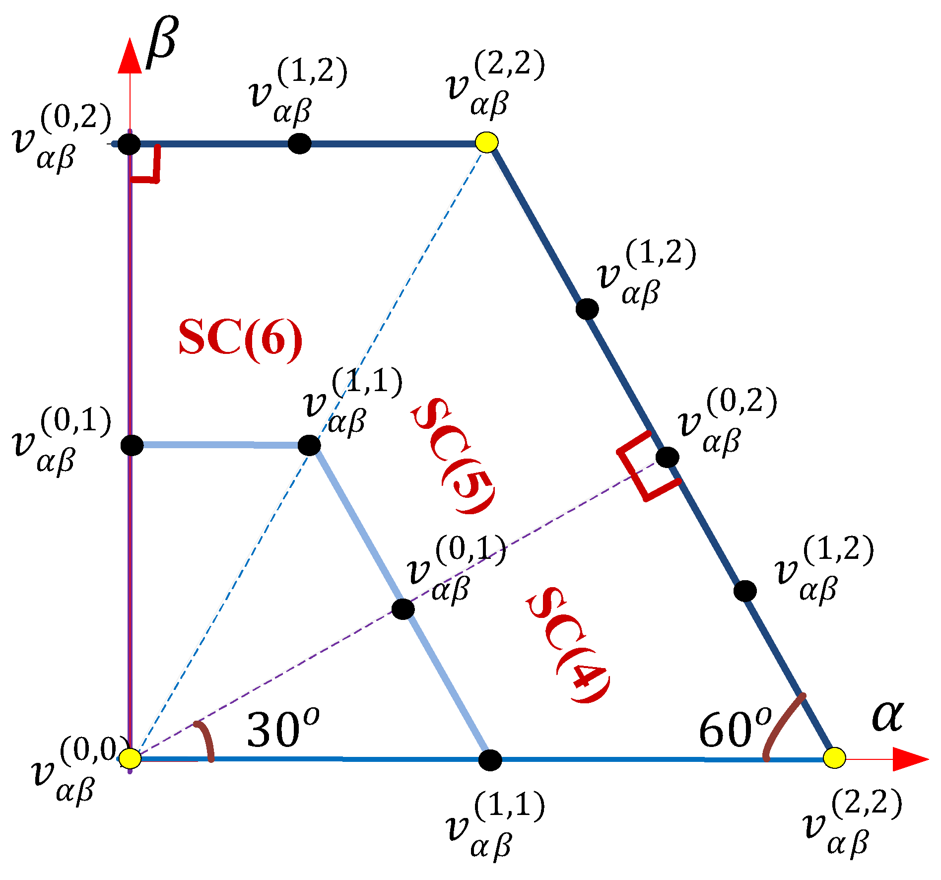
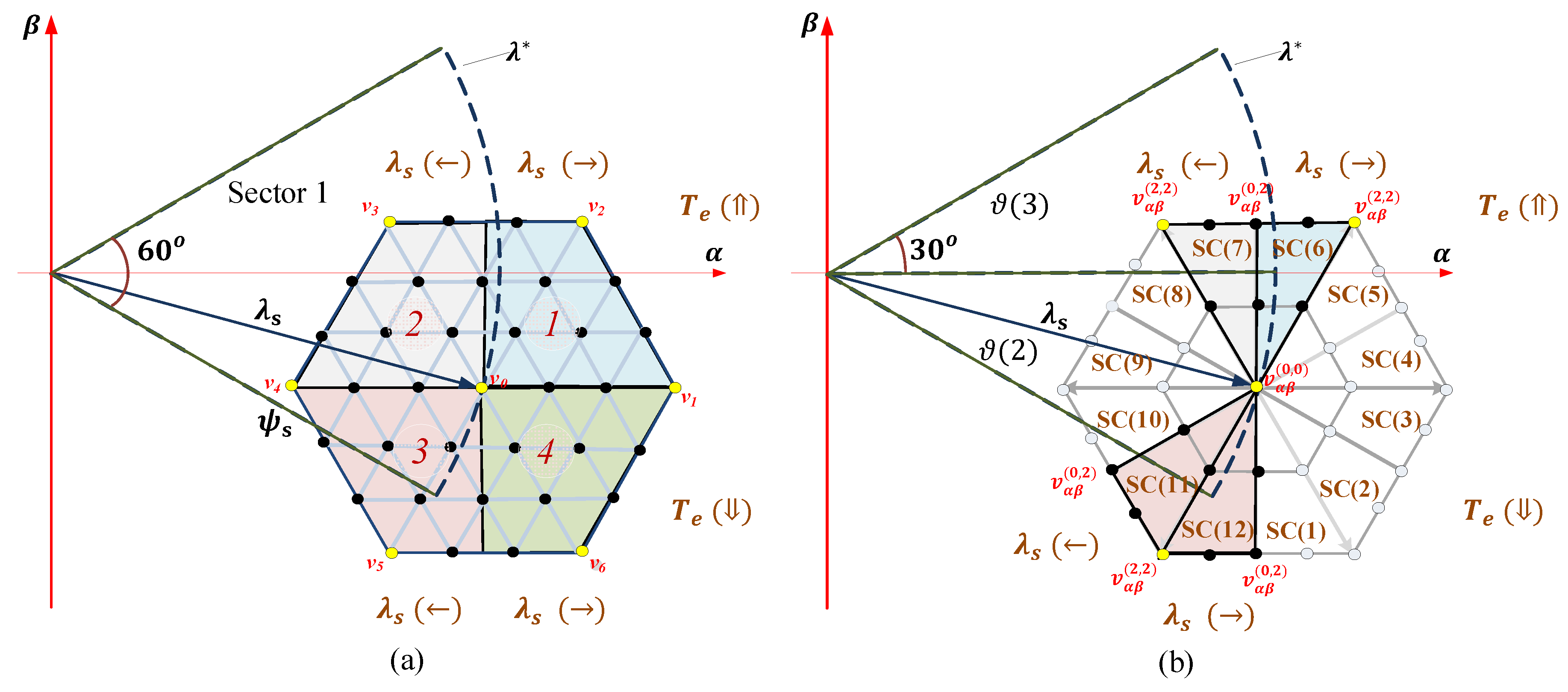
4.1. Synthesis of Virtual Voltage Vectors

In this study, a DSVM strategy can be applied using [19]. Hence, the space vector diagram (SVD) is grouped into concentric hexagonal diagrams (CHDs) with various sized VVs. Each CHD consists of several generated virtual VVs in addition to the real VVs. The number of virtual VVs in each CHD relies on its index digit, as provided in the following mathematical expression:
n ( m ) = 12 × m , { [ m = 1 ~   Γ ] n ( 0 ) = 1 }
In Equation (10), Γ represents the quantity of CHDs. Figure 3b illustrates the proposed SVD with real VVs and synthesized virtual VVs when Γ is 2. The number of VVs is computed according to Equation (10), which equals 37 VVs. The yellow and black dots imply the real and virtual VVs, respectively. Obviously, it is shown that the SVD is partitioned into 12 regions (i.e., SC(1)–SC(12)). In each region, there are six VVs, including a zero-VV.
The real and virtual VVs in the stationary α β plane are given by:
v α ( x , y ) = ( v D C . a v g / 6 × M ) [ ( a 1 + 2 × a 5 ) × x + 3 a 2 × y ]
v β ( x , y ) = ( 3 × v D C . a v g / 6 × M ) [ a 3 × x + ( a 4 + 2 × a 6 ) × y ]
where vDC.avg represents the computed DC-link voltage of the inverter stage, x and y signify the values of each coordinate for each SVD region, and the coefficients (a1, a2 … a6) are attained from Table 2 [18]. Figure 4 illustrates the coordinate values of α β VVs in regions SC(4), SC(5), and SC(6) when Γ = 2.

4.2. Predicted Voltage Vectors

The calculation burden in the prediction stage rises due to the increase in virtual VVs, which also leads to a very large sampling time. Thus, a control approach to lessen the large computation requirement on the microcontroller or digital signal processor (DSP) is necessary.
To lower the number of VVs and, hence, the calculation burden, a computation reduction approach for selecting optimal VVs is proposed by taking into account the flux and torque errors like in the DTC strategy. The prediction vectors in Figure 3b (i.e., proposed SVD) are selected using the sign of the torque error ( T e r r = T T e ) , flux error ( λ e r r = λ | λ s | ) , and the angle of the stator flux ( ϑ ) . The flux position is calculated based on the α β stator flux as:
ϑ = arctan ( λ β / λ α )
To enhance the performance of the prediction, the number of flux positions is split into 12 sectors, as presented in Figure 5. Each flux position is within 30°. After attaining the required sector, the optimal region of the SVD for each flux position is determined to further decrease the computation burden according to Table 3. To clarify this preselection strategy, an example of the selection of VVs of the SVD region when the stator flux vector is positioned at ϑ (2) is shown in Figure 6. In this flux position, there are four optimal voltage regions depending on the flux and torque errors to satisfy the reduction and increase in torque and flux similar to the DTC. For instance, if λ e r r < 0 and T e r r < 0 , the VVs in the optimal SVD region 7 are selected. If λ e r r 0 and T e r r < 0 , the VVs in the optimal region 6 on the proposed SVD are chosen. In the same way, the optimal SVD region 12 is selected when λ e r r 0 and T e r r 0 are assured. However, the selection of SVD region 11 in ϑ (2) is ensured if λ e r r < 0 and T e r r 0 are satisfied.
Hence, only six VVs are taken into account rather than 37. The 2L-VSI consists of eight VVs during the calculation and prediction process. It is worth noting that only VVs in the selected SVD region are produced. In this way, the possible VVs are constrained, which substantially reduces the computation burden on the DSP.

4.3. Delay Compensation

To compensate for the delay in the experimental implementation, the voltage vectors at instant k+2 for forecasting the variables (i.e., i o ( k + 2 ) , λ s ( k + 2 ) , and T e ( k + 2 ) ) are computed in the cost function rather than time instant k + 1. Thus, to obtain the optimal VV among the generated six VVs in the chosen SVD region, a cost function needs to be constructed as:
g = | T T e ( k + 2 ) | + Q | λ | λ s ( k + 2 ) | |
Finally, when the optimal VV vopt in the α β plane is attained depending on the selected SVD region, it needs to be sent to the carrier-based modulation in the next sampling time.

4.4. Overall Control Algorithm for VSI Stage

The complete control process of the proposed FS-PTC with DSVM of PMSM fed by an IMC can be summarized in the following sequences:
  • Obtain the averaged DC-link voltage vDC.avg from the CSR stage.
  • Estimate the motor variables: stator flux and electrical torque.
  • Predict the stator current, stator flux, and torque by the application of the optimal VV.
  • Obtain the optimal SVD region according to the electrical torque and flux errors at the specified flux angle based on Table 3.
  • Calculate the VVs in the α β frame using the rectified voltage vDC.avg based on the selected SVD region using Equations (11) and (12), and according to the coefficients in Table 2.
  • Predict the stator flux, stator current, and torque taking into consideration one step forward to eliminate the delay. Then, the calculated VVs from the selected SVD region are evaluated using the cost function in Equation (14).
  • Choose the optimal VV vopt that reduces the cost function objectives to use at the next sampling cycle for synchronization with CSR and modulation using a carrier-based PWM.
Figure 7 shows the complete control for the proposed PTC for the IMC-fed PMSM.

4.5. Modulation Strategy for VSI of IMC

As stated earlier, the VSI and CSR stages of IMC have to be correlated using a carrier-based PWM to attain safe commutation and stable output voltages for each sampling cycle. The commutation of the CSR stage always occurs because the zero voltage vectors in the inverter stage are used [7]. Therefore, the switching vectors of the CSR and VSI stages are managed to attain the zero DC-link current commutation at the rectifier stage. In this way, a safe commutation can be obtained without a complicated multistep commutation.
The PWM outputs to the inverter are produced by two modulation signals for each phase compared with the triangular carrier. It is worth mentioning that the two modulation signals are determined using the duty cycles (dx and dy) in the CSR stage, vDC.avg, and optimal reference voltages (Va*, Vb*, and Vc*) of each phase obtained by the proposed FS-PTC. The detailed information about the modulation approach for the VSI of an IMC using the carrier-based PWM can be found in [7]. Hence, the modulation signals (VaT* and VaB*) for the top and bottom legs of the α-phase are given as:
V a T = 2 d y × V a + v s n v D C . a v g + d x V a B = 2 d x × V a + v s n v D C . a v g d y
where vsn is the zero-sequence component (referred to as offset voltage) of the three optimal reference voltages, which is given by:
v s n = 0.5 × { max ( V a , V b , V c ) + min ( V a , V b , V c ) }
A similar calculation of modulation signals can be applied to the other optimal reference voltages (Vb* and Vc*). Finally, the modulated signals are compared with the PWM carrier and sent to the IMC inverter.

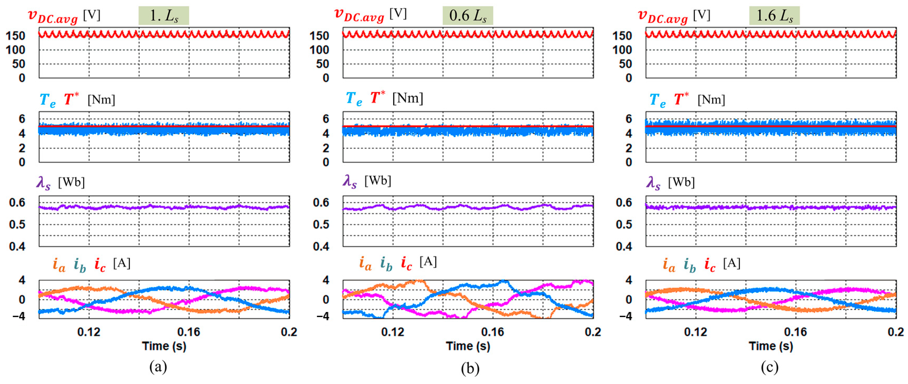
5. Simulation Results

The proposed FS-PTC of the PMSM fed by an IMC was simulated using PSIM software. The motor and LC filter parameters are given in Table 4. The reference flux was set to 0.58.
The simulation configuration is similar to the schematic depicted in Figure 1. For the simulation of the complete control system, the sampling interval was designed as 100 μs in line with the experiment. Hence, due to the commutation process [7], the switching frequencies of the CSR stage and VSI stage are 10 and 20 kHz, respectively. It is worth mentioning that the conventional FS-PTC can cause unsafe commutation in the indirect matrix converter because it only involves a single switching state during the entire sampling cycle. Hence, for the sake of investigation of the proposed FS-PTC of the PMSM fed by an IMC, a comparison is performed between Γ = 1 and Γ = 2. For better identification, PTC-SVD-1 represents Γ = 1, in which the number of VVs is 13, and PTC-SVD-2 represents Γ = 2, which indicates the number of VVs is 37. The PTC-SVD-1 is closer to the conventional FS-PTC in terms of the number of VVs. Both PTC-SVD-1 and PTC-SVD-2 methods are investigated under the same weighting factor for fair comparison.
Figure 8 depicts the simulation results for the output voltage of the CSR stage in the IMC circuit. Initially, the input three-phase line-to-line voltages (vuv, vvw, and vwu) from the AC grid are rectified as explained in Section 2 to produce a fictitious DC-link voltage (vDC), which can be averaged as shown in the subplot of the averaged DC-link voltage vDC.avg. The vDC.avg is computed depending on the duty ratios dx and dy, whereas vDC is produced by the modulation of the CSR stage. The average voltage is utilized by the inverter side in the IMC to control the PMSM.
Figure 9 and Figure 10 show the simulation results of the steady-state performance at 200 rpm and 5 Nm for the PTC-SVD-1 and PTC-SVD-2 of the PMSM fed by the IMC, respectively. Additionally, both figures show the impact of stator inductance changes from 60% up to 160% of the nominal value. Comparing the performances of the PTC-SVD-1 and the PTC-SVD-2 under nominal inductance, the PTC-SVD-2 shows a considerable decrease in the ripples of torque and flux as shown in Figure 10b. In addition, it can be observed that the PTC-SVD-2 has more stable flux and fewer current distortions compared to the PTC-SVD-1 method. When the stator inductance Ls changed to 60% of nominal inductance for both methods, the torque ripple reduced with higher increase in the flux ripple and current distortion as shown in Figure 9b and Figure 10b. Changing the Ls to 160% of nominal value results in increasing the torque ripple and reduction of flux ripple and current distortions, as shown in Figure 9c and Figure 10c. Nevertheless, the proposed PTC-SVD-2 in Figure 10b,c shows a better performance and higher robustness under parameter variation compared to the results of PTC-SVD-1.
Figure 11 shows the FFT waveforms of the A-phase current output (ia) at 300 rpm for the PTC-SVD-1 and PTC-SVD-2 methods, respectively. It can be observed that the PTC-SVD-2 has fewer harmonic, particularly below 5 kHz, due to the larger number of candidate virtual VVs. From both spectral waveforms, it is obvious that the switching frequency is constant at 20 kHz as shown by the 1st harmonic component for both PTC methods. Notably, the switching frequency of the inverter of the IMC is twice that of the CSR due to the commutation process [7].
Figure 12 illustrates the dynamic torque performance of PTC-SVD-1 and PTC-SVD-2 methods when the torque reference was stepped from 1 to 10 Nm at a speed load of 300 rpm. It can be observed that the torque performance in the proposed PTC-SVD-2 was slightly faster than that in the PTC-SVD-1 method. Moreover, the proposed PTC-SVD-2 method has reduced toque ripple at both torque references compared to the PTC-SVD-1 method.

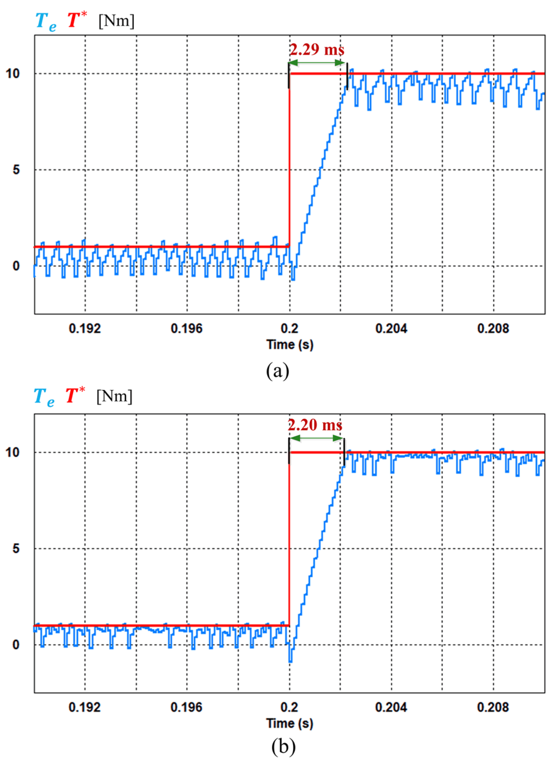
6. Implementation and Experimental Results

The performance of the FS-PTC for the IMC-fed PMSM was implemented using a DSP (TMS320C28346) and a field-programmable gate array (FPGA). Figure 13 presents the experimental setup, which involves the PMSM coupled with the loading induction machine (IM), a power board, and a control board. The power board comprises the CSR and VSI using the IGBT and gate drivers. The IM was used as a load controlled by a commercially available YASUKAWA inverter. The AC source rectification and proposed FS-PTC with the DSVM algorithms for the IMC-fed PMSM was written on the DSP using C programming language. Moreover, the PWM block for both CSR and VSI was programmed using VDHL in the FPGA. The optimal VV is sent to the PWM block in the FPGA to create and feed the three control signals to the VSI. The parameters utilized in the experiment were similar to those provided in Table 4. The LC-filter parameters were empirically selected from the available sets of equipment. Similar to the simulation, the sampling interval of the DSP for both the CSR and VSI stages was 100 μs for the whole proposed control approach under the same weighting factor.
Figure 14 presents the experimental results for the input grid voltages for the u-phase voltage (vun) and v-phase voltage (vvn). The third phase, the w-phase voltage (vwn), is not shown due to the limitation of the measuring equipment. By utilizing the CSR stage, the input grid voltage was rectified to generate the average value of the DC voltage vDC.avg. As previously mentioned, vDC.avg is calculated based on the duty ratios dx and dy.
Figure 15a,b shows the experimental results of the electrical torque, flux, and current for the PTC-SVD-1 and PTC-SVD-2, respectively. The computation of torque ripple (Tripple) and flux ripple ( λ r i p p l e ) for all control methods, as indicated in the figures, was performed during steady-state operation, as in [32]. Both methods were at steady-state operation at a speed of 200 rpm with 3.0 Nm. The PTC-SVD-2 showed superior performance in terms of torque and flux ripple reduction as indicated by the averaged torque and flux ripples in Figure 15. In addition, the output stator current in the PTC-SVD-2 has less ripple and distortion compared to PTC-SVD-1.
Figure 16 depicts the experimental results of the dynamic torque performance for the PTC-SVD-1 and PTC-SVD-2 methods as the torque reference was stepped from 1 to 5 Nm. It is evident that the proposed PTC-SVD-2 has a faster torque dynamic performance than that of the PTC-SVD-1 method. Moreover, the averaged torque ripples indicated in PTC-SVD-2 are lower than those in PTC-SVD-1 for both torque references.
Table 5 shows a comparison between the conventional FS-PTC, PTC-SVD-1, and PTC-SVD-2 in terms of number of predicted vectors for cost function evaluation, possibility of implementation in IMC, and computation burden. It can be seen that the conventional FS-PTC has the smallest computation burden, however it does not guarantee safe implementation for the IMC. The computation time of PTC-SVD-1 is slightly smaller than that of PTC-SVD-2, however, the PTC-SVD-2 has better performance in terms of output waveform quality and robustness.

7. Conclusions

This study presented an improved FS-PTC for a high-performance indirect matrix converter-fed PMSM drive. The indirect matrix converter does not require a DC-link capacitive element, which can reduce the volume and size of the PMSM drive. The conventional FS-PTC can cause unsafe commutation for the rectifier stage in the indirect matrix converter because it only applies a single switching state during the entire sampling period. Thus, the DSVM-based PTC methods, PTC-SVD-1 (13 VVs) and PTC-SVD-2 (37 VVs), were compared in the simulation and experimental results using the proposed selection method. From these results, the PTC-SVD-2 achieved better steady-state and dynamic torque performances compared to PTC-SVD-1. Additionally, the PTC-SVD-2 showed more robust characteristics against parameter variations than PTC-SVD-1. This improvement can be attributed to the increased number of virtual voltage vectors in the prediction process. In both PTC-SVD methods, the switching frequency of the inverter was constant and twice that of the sampling frequency due to the correlation between the inverter and rectifier stage of the converter. The computation time is reduced using the preselection strategy based on the flux and torque demands for each positioned flux sector without the need for voltage vector lookup tables.

Author Contributions

Conceptualization and writing—original draft, methodology and simulation, formal analysis, I.M.A.; Experimental validation, I.M.A. and Y.B. Resources, review, and editing, K.-B.L. All authors have read and agreed to the published version of the manuscript.

Funding

This research was supported in part by Korea Electric Power Corporation under Grant R19XO01-20 and in part by “Human Resources Program in Energy Technology” of the Korea Institute of Energy Technology Evaluation and Planning (KETEP), granted financial resource from the Ministry of Trade, Industry & Energy, Korea under Grant 20194030202370.

Conflicts of Interest

The authors declare no conflict of interest.

References

  1. Jussila, M.; Tuusa, H. Comparison of simple control strategies of space-vector modulated indirect matrix converter under distorted supply voltage. IEEE Trans. Power Electron. 2007, 22, 139–148. [Google Scholar] [CrossRef]
  2. Siami, M.; Khaburi, D.A.; Rivera, M.; Rodríguez, J. A Computationally Efficient Lookup Table Based FCS-MPC for PMSM Drives Fed by Matrix Converters. IEEE Trans. Ind. Electron. 2017, 64, 7645–7654. [Google Scholar] [CrossRef]
  3. Siami, M.; Khaburi, D.A.; Abbaszadeh, A.; Rodriguez, J. Robustness Improvement of Predictive Current Control Using Prediction Error Correction for Permanent Magnet Synchronous Machines. IEEE Trans. Ind. Electron. 2016, 63, 3458–3466. [Google Scholar] [CrossRef]
  4. López, M.; Rodriguez, J.; Silva, C.; Rivera, M. Predictive torque control of a multidrive system fed by a dual indirect matrix converter. IEEE Trans. Ind. Electron. 2015, 62, 2731–2741. [Google Scholar] [CrossRef]
  5. Sun, Y.; Li, X.; Su, M.; Wang, H.; Dan, H.; Xiong, W. Indirect Matrix Converter-Based Topology and Modulation Schemes for Enhancing Input Reactive Power Capability. IEEE Trans. Power Electron. 2015, 30, 4669–4681. [Google Scholar] [CrossRef]
  6. Bak, Y.; Lee, K.B. Constant speed control of a permanent magnet synchronous motor using a reverse matrix converter under variable generator input conditions. IEEE J. Emerg. Sel. Topics Power Electron. 2018, 6, 315–326. [Google Scholar] [CrossRef]
  7. Nguyen, T.D.; Lee, H. Dual Three-Phase Indirect Matrix Converter with Carrier-Based PWM Method. IEEE Trans. Power Electron. 2014, 29, 569–581. [Google Scholar] [CrossRef]
  8. Bak, Y.; Lee, K.-B. Reducing switching losses in indirect matrix converter drives: Discontinuous PWM method. J.Power Electron. 2018, 18, 1325–1335. [Google Scholar]
  9. Rodriguez, J.; Kolar, J.; Espinoza, J.; Rivera, M.; Rojas, C. Predictive torque and flux control of an induction machine fed by an indirect matrix converter. In Proceedings of the IEEE International Conf. on Industrial Technology, Vina del Mar, Chile, 14–17 March 2010; pp. 1857–1863. [Google Scholar]
  10. Kim, K.Y.; Bak, Y.; Park, J.-H.; Lee, K.-B. Model predictive control using subdivided voltage vectors for current ripple reduction in an indirect matrix converter. In Proceedings of the 2018 International Power Electronics Conference (IPEC-Niigata 2018 -ECCE Asia), Niigata, Japan, 20–24 May 2018; pp. 4104–4108. [Google Scholar]
  11. Correa, P.; Rodriguez, J.; Rivera, M.; Espinoza, J.R.; Kolar, J.W. Predictive control of an indirect matrix converter. IEEE Trans. Ind. Electron. 2009, 56, 1847–1853. [Google Scholar] [CrossRef]
  12. Kim, J.K.Y.; Bak, Y.; Lee, K.-B. Predictive current control for indirect matrix converter with reduced current ripple. J. Power Electron. 2020, 20, 443–454. [Google Scholar] [CrossRef]
  13. Rodriguez, J.; Pontt, J.; Silva, C.A.; Correa, P.; Lezana, P.; Cortes, P.; Ammann, U. Predictive current control of a voltage source inverter. IEEE Trans. Ind. Electron. 2007, 54, 495–503. [Google Scholar] [CrossRef]
  14. Rivera, M.; Rodriguez, J.; Wu, B.; Espinoza, J.R.; Rojas, C.A. Current Control for an Indirect Matrix Converter with Filter Resonance Mitigation. IEEE Trans. Ind. Electron. 2012, 59, 71–79. [Google Scholar] [CrossRef]
  15. Adase, L.A.; Alsofyani, I.M.; Lee, K. Predictive Torque Control with Simple Duty-Ratio Regulator of PMSM for Minimizing Torque and Flux Ripples. IEEE Access 2020, 8, 2373–2381. [Google Scholar] [CrossRef]
  16. Hakami, S.S.; Alsofyani, I.M.; Lee, K. Torque Ripple Reduction and Flux-Droop Minimization of DTC With Improved Interleaving CSFTC of IM Fed by Three-Level NPC Inverter. IEEE Access 2019, 7, 184266–184275. [Google Scholar] [CrossRef]
  17. Alsofyani, I.; Lee, K. Enhanced Performance of Constant Frequency Torque Controller-Based Direct Torque Control of Induction Machines with Increased Torque-Loop Bandwidth. IEEE Trans. Ind. Electron. 2020, 67, 10168–10179. [Google Scholar] [CrossRef]
  18. Lee, J.; Lee, J.; Moon, H.; Lee, K. An Improved Finite-Set Model Predictive Control Based on Discrete Space Vector Modulation Methods for Grid-Connected Three-Level Voltage Source Inverter. IEEE J. Emerg. Sel. Topics Power Electron. 2018, 6, 1744–1760. [Google Scholar] [CrossRef]
  19. Alsofyani, I.M.; Lee, K.B. Finite-Set Predictive Torque Control Based on Sub-divided Voltage Vectors of PMSM with Deadbeat Control and Discrete Space Vector Modulation. In Proceedings of the 2019 IEEE Applied Power Electronics Conference and Exposition (APEC), Anaheim, CA, USA, 17–21 March 2019; pp. 1853–1857. [Google Scholar]
  20. Casadei, D.; Serra, G.; Tani, K. Implementation of a direct control algorithm for induction motors based on discrete space vector modulation. IEEE Trans. Power Electron. 2000, 15, 769–777. [Google Scholar] [CrossRef]
  21. Guo, Y.; Sun, H.; Zhang, Y.; Liu, Y.; Li, X.; Xue, Y. Duty-Cycle Predictive Control of Quasi-Z-Source Modular Cascaded Converter Based Photovoltaic Power System. IEEE Access 2020, 8, 172734–172746. [Google Scholar] [CrossRef]
  22. Zhou, Z.; Xia, C.; Yan, Y.; Wang, Z.; Shi, T. Torque Ripple Minimization of Predictive Torque Control for PMSM With Extended Control Set. IEEE Trans. Ind. Electron. 2017, 64, 6930–6939. [Google Scholar] [CrossRef]
  23. Wang, Y.; Wang, X.; Xie, W.; Wang, F.; Dou, M.; Kennel, R.M.; Lorenz, R.D.; Gerling, D. Deadbeat Model-Predictive Torque Control with Discrete Space-Vector Modulation for PMSM Drives. IEEE Trans. Ind. Electron. 2017, 63, 3537–3547. [Google Scholar] [CrossRef]
  24. Moon, H.; Lee, J.; Lee, K. A Robust Deadbeat Finite Set Model Predictive Current Control Based on Discrete Space Vector Modulation for a Grid-Connected Voltage Source Inverter. IEEE Trans. Energy Convers. 2018, 33, 1719–1728. [Google Scholar] [CrossRef]
  25. Hu, J. Improved Dead-Beat Predictive DPC Strategy of Grid-Connected DC-AC Converters with Switching Loss Minimization and Delay Compensations. IEEE Trans. Ind. Inform. 2013, 8, 728–738. [Google Scholar] [CrossRef]
  26. Alsofyani, I.M.; Lee, K.-B. Improved deadbeat FC-MPC based on the discrete space vector modulation method with efficient computation for a grid-connected three-level inverter system. Energies 2019, 12, 3111. [Google Scholar] [CrossRef] [Green Version]
  27. Moon, H.-C.; Lee, J.-S.; Lee, J.-H.; Lee, K.-B. MPC-SVM method with subdivision strategy for current ripples reduction and neutral-point voltage balance in three-level inverter. In Proceedings of the 2017 IEEE Energy Conversion Congress and Exposition (ECCE), Cincinnati, OH, USA, 1–5 October 2017; pp. 191–196. [Google Scholar]
  28. Osman, I.; Xiao, D.; Alam, K.S.; Akter, M.P.; Shakib, S.M.S.I.; Rahman, M.F. Discrete Space Vector Modulation Based Model Predictive Torque Control with No Sub-Optimization. IEEE Trans. Ind. Electron. 2020, 67, 8164–8174. [Google Scholar] [CrossRef]
  29. Kim, K.Y.; Bak, Y.; Lee, K. Model Predictive Current Control for a PMSM Fed by an Indirect Matrix Converter with Torque Ripple Reduction. In Proceedings of the 2019 IEEE Applied Power Electronics Conference and Exposition (APEC), Anaheim, CA, USA, 17–21 March 2019; pp. 1891–1896. [Google Scholar]
  30. Amiri, M.; Milimonfared, J.; Khaburi, D.A. Predictive Torque Control Implementation for Induction Motors Based on Discrete Space Vector Modulation. IEEE Trans. Ind. Electron. 2018, 65, 6881–6889. [Google Scholar] [CrossRef]
  31. Vazquez, S.; Leon, J.I.; Franquelo, L.G.; Carrasco, J.M.; Martinez, O.; Rodriguez, J.; Cortes, P.; Kouro, S. Model predictive control with constant switching frequency using a discrete space vector modulation with virtual state vectors. In Proceedings of the 2009 IEEE International Conference on Industrial Technology, Gippsland, Australia, 10–13 February 2009; pp. 1–6. [Google Scholar]
  32. Alsofyani, I.M.; Lee, K.-B. Predictive Torque Control Based on Discrete Space Vector Modulation of PMSM without Flux Error-Sign and Voltage-Vector Lookup Table. Electronics 2020, 9, 1542. [Google Scholar] [CrossRef]
Figure 1. Schematic of an indirect matrix converter (IMC) applied to a permanent magnet synchronous motor (PMSM) drive system.
Electronics 09 02133 g001
Figure 2. Space vector diagram of the current source rectifier (CSR) side.
Electronics 09 02133 g002
Figure 3. Space voltage diagrams for (a) conventional finite set-predictive torque control (FS-PTC) and (b) proposed FS-PTC.
Electronics 09 02133 g003
Figure 4. Coordinate values of the voltage vectors in SC(4), SC(5), and SC(6) applied in the proposed FS-PTC of a PMSM fed by an IMC.
Electronics 09 02133 g004
Figure 5. Flux sector distribution for (a) conventional 6 sectors (b) proposed 12 sectors.
Electronics 09 02133 g005
Figure 6. The space vector diagram (SVD) region selection depending on the flux and torque demands for (a) conventional PTC-based discrete space-vector modulation (DSVM) at Sector 1 and (b) proposed PTC-based DSVM at ϑ ( 2 ) .
Electronics 09 02133 g006
Figure 7. Control block illustration for the proposed FS-PTC of the PMSM fed by an IMC.
Electronics 09 02133 g007
Figure 8. Simulation results of input-line to line voltages, DC-link voltage, and average DC-link voltage of the IMC.
Electronics 09 02133 g008
Figure 9. Simulation steady-state response of PTC-SVD-1 of a PMSM fed by an IMC at 5 Nm. (a) Ls = 0.0156. (b) Ls = 0.00936. (c) Ls = 0.02496.
Electronics 09 02133 g009
Figure 10. Simulation steady-state response of PTC-SVD-2 of a PMSM fed by an IMC at 5 Nm. (a) Ls = 0.0156. (b) Ls = 0.00936. (c) Ls = 0.02496.
Electronics 09 02133 g010
Figure 11. Simulation results of FFT waveforms for (a) PTC-SVD-1 and (b) PTC-SVD-2 of a PMSM fed by an IMC.
Electronics 09 02133 g011
Figure 12. Simulation dynamic torque response for (a) PTC-SVD-1 and (b) PTC-SVD-2 of a PMSM fed by an IMC.
Electronics 09 02133 g012
Figure 13. Experimental setup.
Electronics 09 02133 g013
Figure 14. Experimental results of the input phase voltages (vun and vwn) and the average value of the hypothetical DC-link voltage (vDC-av) of the IMC.
Electronics 09 02133 g014
Figure 15. Experimental steady-state response for (a) PTC-SVD-1 and (b) PTC-SVD-2 of a PMSM fed by an IMC at 3 Nm.
Electronics 09 02133 g015
Figure 16. Experimental dynamic torque response for (a) PTC-SVD-1 and (b) PTC-SVD-2 of a PMSM fed by an IMC.
Electronics 09 02133 g016
Table 1. Switching patterns and averaged amounts of the DC-link voltage.
SectorLimit of θ u on SwitchModulated SwitchesvDC.avg
1 π / 6 θ u < π / 6 SuTSvBSwB d x v u v d y v w v
2 π / 6 θ u < π / 2 SwBSuTSvT d x v w u + d y v v w
3 π / 2 θ u < 5 π / 6 SvTSwBSuB d x v v w d y v u v
4 5 π / 6 θ u < 7 π / 6 SuBSvTSwT d x v u v + d y v w u
5 7 π / 6 θ u < 9 π / 6 SwTSuBSvB d x v w u d y v v w
6 9 π / 6 θ u < 11 π / 6 SvBSwTSuT d x v v w + d y v u v
Table 2. Coefficients for each voltage vector region.
SVD Regiona1a2a3a4a5a6
SC(1)11–1100
SC(2)−111100
SC(3)000011
SC(4)0000−11
SC(5)1−11100
SC(6)−1−1–1100
SC(7)−1−11−100
SC(8)1–1–1–100
SC(9)0000−1−1
SC(10)00001−1
SC(11)−11−1−100
SC(12)111−100
Table 3. Optimum voltage vector zone for each flux sector.
Flux Position λ e r r ( ) λ e r r ( )
T e r r ( ) T e r r ( ) T e r r ( ) T e r r ( )
ϑ (1) SC(5)SC(11)SC(6)SC(10)
ϑ (2)SC(6)SC(12)SC(7)SC(11)
ϑ (3)SC(7)SC(1)SC(8)SC(12)
ϑ (4)SC(8)SC(2)SC(9)SC(1)
ϑ (5)SC(9)SC(3)SC(10)SC(2)
ϑ (6)SC(10)SC(4)SC(11)SC(3)
ϑ (7)SC(11)SC(5)SC(12)SC(4)
ϑ (8)SC(12)SC(6)SC(1)SC(5)
ϑ (9)SC(1)SC(7)SC(2)SC(6)
ϑ (10)SC(2)SC(8)SC(3)SC(7)
ϑ (11)SC(3)SC(9)SC(4)SC(8)
ϑ (12)SC(4)SC(10)SC(5)SC(9)
Table 4. PMSM and LC filter parameters.
PMSM Parameters
Rated torque (N∙m)60
Rated current (A)19.9
Rated speed (r/min)1750
Rated power (kW)11
Number of poles6
Stator resistance (Ω)0.349
Stator inductance (mH)15.6
Permanent magnet flux (Wb)0.554
LC Filter Parameters
Input filter inductance (mH)1.3
Input filter capacitance (μF)1.5
Table 5. Comparison between conventional FS-PTC, PTC-SVD-1, and PTC-SVD-2.
Control MethodConventional FS-PTCPTC-SVD-1PTC-SVD-2
Number of Predicted vectors836
IMC implementationNot safeSafeSafe
Computation time37 µs48 µs52 µs
Publisher’s Note: MDPI stays neutral with regard to jurisdictional claims in published maps and institutional affiliations.

