Article

Coordinated Control Scheme of Battery Storage System to Augment LVRT Capability of SCIG-Based Wind Turbines and Frequency Regulation of Hybrid Power System

1
Department of Electrical and Electronic Engineering, American International University-Bangladesh (AIUB), 408/1, Kuratoli, Khilkhet, Dhaka 1229, Bangladesh
2
Department of Electrical and Electronic Engineering, Kitami Institute of Technology (KIT), 165 Koen-cho, Kitami, Hokkaido 090-8507, Japan
*
Author to whom correspondence should be addressed.
Submission received: 12 January 2020 / Revised: 26 January 2020 / Accepted: 29 January 2020 / Published: 1 February 2020
(This article belongs to the Special Issue Grid-Connected Renewable Energy Sources)

Abstract

:
Fixed speed wind turbine-squirrel cage induction generator (FSWT-SCIG)-based wind farms (WFs) are increasing significantly. However, FSWT-SCIGs have no low voltage ride-through (LVRT) and frequency control capabilities, which creates a significant problem on power system transient and steady-state stability. This paper presents a new operational strategy to control the voltage and frequency of the entire power system, including large-scale FSWT-SCIG-based WFs, by using a battery storage system (BSS). The proposed cascaded control of the BSS is designed to provide effective quantity of reactive power during transient periods, to augment LVRT capability and real power during steady-state periods in order to damp frequency fluctuations. The cascaded control technique is built on four proportional integral (PI) controllers. The droop control technique is also adopted to ensure frequency control capability. Practical grid code is taken to demonstrate the LVRT capability. To evaluate the validity of the proposed system, simulation studies are executed on a reformed IEEE nine-bus power system with three synchronous generators (SGs) and SCIG-based WF with BSS. Triple-line-to-ground (3LG) and real wind speed data are used to analyze the hybrid power grid’s transient and steady-state stability. The simulation results indicate that the proposed system can be an efficient solution to stabilize the power system both in transient and steady-state conditions.

1. Introduction

Wind energy is a clean energy, the use of which can avoid 5.6 billion tons of CO2 by 2050, equivalent to the yearly emissions of the 80 most polluting cities in the world, home to around 720 million people [1]. This would help to save up to four million lives annually by 2030 by reducing pollution, because one in eight deaths in the world is linked to air pollution [1].
The total worldwide wind power capacity in 2015 was 432.9 GW, which is a summative market growth of more than 17% [2,3,4]. By 2030, wind power could exceed 2110 GW and supply up to 20% of worldwide power demands [4].

1.1. Motivation

This massive penetration of wind energy into the power system, replacing fossil fuel-based power plants, has introduced some burdens to the power grid.
Basically, fixed speed wind turbine-squirrel cage induction generators (FSWT-SCIGs) are mostly used to develop wind farms (WFs). SCIGs have some advantages, such as their low cost, fewer maintenance requirements, good speed regulation, high efficiency in converting mechanical energy to electrical energy, better heat regulation, small size, and light weight. However, they cannot ensure low voltage ride-through (LVRT) capability and frequency stability of entire power systems during transient and steady-state periods [5], respectively.

1.2. Literature Reviews

Many auxiliary devices can be applied to SCIGs to augment their LVRT capability. For example, a dynamic voltage restorer (DVR) [6], thyristor controlled series capacitor (TCSC) [7], magnetic energy recovery switch (MERS) [8], series dynamic braking resistor (SDBR) [9], fault current limiter (FCL) [10], bridge-type fault current limiter (BFCL) [11], static synchronous compensator (STATCOM) [12], static VAR compensator (SVC) [13], superconductor dynamic synchronous condenser (SDSC) [14], unified compensation system (UCS) [15], and a unified power quality conditioner (UPQC) [15], were installed in SCIGs to inject reactive power in order to ensure LVRT capability.
Even though the LVRT was ensured by using the above-mentioned schemes, there are several drawbacks [6,7,8,9,10,11,12,13,14,15]. For example: TCSC creates resonance and injects objectionable harmonics, DVR has phase angle jumps and absorbs real power, SDBR and SFCL cannot control reactive power, MERS necessitates mechanical bypass switches, BFCL needs a large-scale coupling transformer, SVC offers voltage oscillations, STATCOM necessities a cut-off in a high-voltage drop, SDSC is less effective for applications of low-voltage drops, UPQC needs a large dc-link capacitor which increases the system cost, and UCS has high losses of conduction in the series bypass switch [16].
On the other hand, the battery storage system (BSS) is well known, and can respond more swiftly and quicker with better performance [17]. Additionally, it is steadily established technology and has appropriate energy density. Thus, BSS is the most prevalent solution in wind power applications [18].

1.3. Contribution

Therefore, based on the above discussion, a BSS for a SCIG-based WF is proposed in this paper to enhance the LVRT capability during transient periods and to damp frequency oscillations during steady-state periods. A suitable PI controller-based cascaded control approach is constructed to guarantee the stable operation of the power system. The proposed control strategy also incorporates droop gain and frequency signals to provide an effective amount of real power from the BSS which will ensure smaller frequency fluctuations. Detailed design procedures and control strategies are adequately presented in this paper.
The transient and steady-state responses of the entire power system including IEEE nine-bus system, WF with BSS is compared with that of SCIG without BSS. Actual wind speed values of Hokkaido Island, Japan are considered for steady-state analysis.
The simulation results clearly indicate that the proposed strategy can confirm the LVRT capability of WFs, and damp the frequency fluctuations of a hybrid power grid.
The paper is structured in six sections. Section 1 presented the introduction, motivation behind this work, literature reviews, and contribution. Section 2 and Section 3 present the model of a hybrid power system and an aerodynamic model of wind turbine. Section 4 describes the proposed BSS along with its control strategy. The simulation results and analysis are presented in Section 5. Finally, Section 6 concludes the paper with a brief summary.

2. Model of a Hybrid Power System

The hybrid power system model presented in Figure 1 is used for transient and steady-state analysis. It has a WF and IEEE nine-bus main model. Basically, three different conventional synchronous generators (SGs) are used for the main system. The ratings of the SGs are 150 MVA (SG1), 250 MVA (SG2), and 200 MVA (SG3).
An AC4A-type exciter model is used for all SGs as shown in Figure 2 [19]. The thermal-based power station as depicted in Figure 3 is considered for SG1 and SG2, and the hydro-based power station is considered for SG3 as illustrated in Figure 4 [19].
Here, the FSWT-SCIG is linked to the main system at Bus 5 through 0.69 kV/66 kV, 66 kV/230 kV transformers and a dual transmission line. It has one SCIG (rated capacity: 100 MW) as shown in Figure 1. The reactive power is delivered to the SCIG using a capacitor bank during steady-state periods. Additionally, the BSS is connected next to the capacitor bank. The capacity of the BSS is 30 MVA. The frequency is 50 Hz and the base power of the power system is 100 MVA. The governor systems of SG1 and SG3 are controlled by an integral control to ensure automatic generation control (AGC) as depicted in Figure 5 [19]. The parameters of the SGs and SCIGs are presented in the Appendix.

3. Model of a Wind Turbine

The expression of the wind turbine’s mechanical power can be written as follows [20]:
P w = 0.5 ρ π R 2 V w 3 C p ( λ , β )
Here, Pw = captured wind power, R = rotor blade radius (m), Cp = power coefficient, ρ = air density (kg/m3), and Vw = wind speed (m/s).
The expression Cp can be written as follows [21]:
C p ( λ , β ) = c 1 ( c 2 λ i c 3 β c 4 ) e c 5 λ i + c 6 λ
1 λ i = 1 λ 0.08 β 0.035 β 3 + 1
λ = ω r R V w
Here, β = pitch angle (deg), ωr = wind turbine rotor speed (rad/s), c1 to c6 = wind turbine characteristic coefficients [21], and λ = tip speed ratio.
Figure 6 presents the characteristics curve of Cp vs. λ. The curve is found for a different β from Equation (2). From the graph, the optimum λ (λopt) = 8.1 and the optimum Cp (Cpopt) = 0.48. Figure 7 shows the model for the blade pitch control system of FSWT [22]. In FSWT, the pitch controller is used to control the real power output of the SCIG when it exceeds the rated power.

4. Proposed Coordinated Control of Battery Storage System

The BSS model which is used in this work is presented in Figure 8. It consists of a lead–acid battery unit, a voltage source converter (VSC) based on pulse width modulation (PWM), and a step-up transformer. For simplicity, the battery is symbolized using a constant DC voltage source. The DC voltage is transformed to grid-synchronized three-phase AC voltage using VSC.
The proposed control technique of the BSS is depicted in Figure 9. The different error signals are compensated using a cascaded control technique based on four PI controllers. The upper portion of the proposed control system controls the real power injected to the power grid system by adjusting the d-axis current (Id), whereas the lower portion is controlling the reactive power injected to the power system by adjusting the q-axis current (Iq). Additionally, in the upper portion the frequency of the grid system (fsys) is taken as feedback. Depending upon the frequency deviation, the upper controller portion will minimize the frequency fluctuations by injecting effective amounts of real power from the BSS during steady-state conditions. The trial and error technique is applied to choose the droop gain (Kp) which ensures optimized results.
In the lower portion, the r.m.s voltage (V) of the grid system is taken as feedback. During transient conditions (e.g., fault conditions), the lower controller portion will inject effective amounts of reactive power until the terminal voltage reaches its pre-fault value.
Finally, the reference voltages (Va*, Vb*, and Vc*) are compared with a high-frequency triangular carrier wave to get the gate drive pulses of the VSC. In this way, the LVRT’s capability and minimization of frequency fluctuations can be ensured.

5. Simulation Results

In this work, simulation investigation has been completed on the same hybrid power system model presented in Figure 1. The well-known PSCAD/EMTDC software is used for simulation analysis. Due to detailed modeling of the whole system, the simulation time step is taken as 10 µs. The system frequency is 50 Hz. Two case studies are executed in order to authenticate the appropriateness of the proposed BSS. In Case 1, simulation scrutiny is accomplished without BSS, and in Case 2, simulation scrutiny is accomplished by including the proposed BSS.

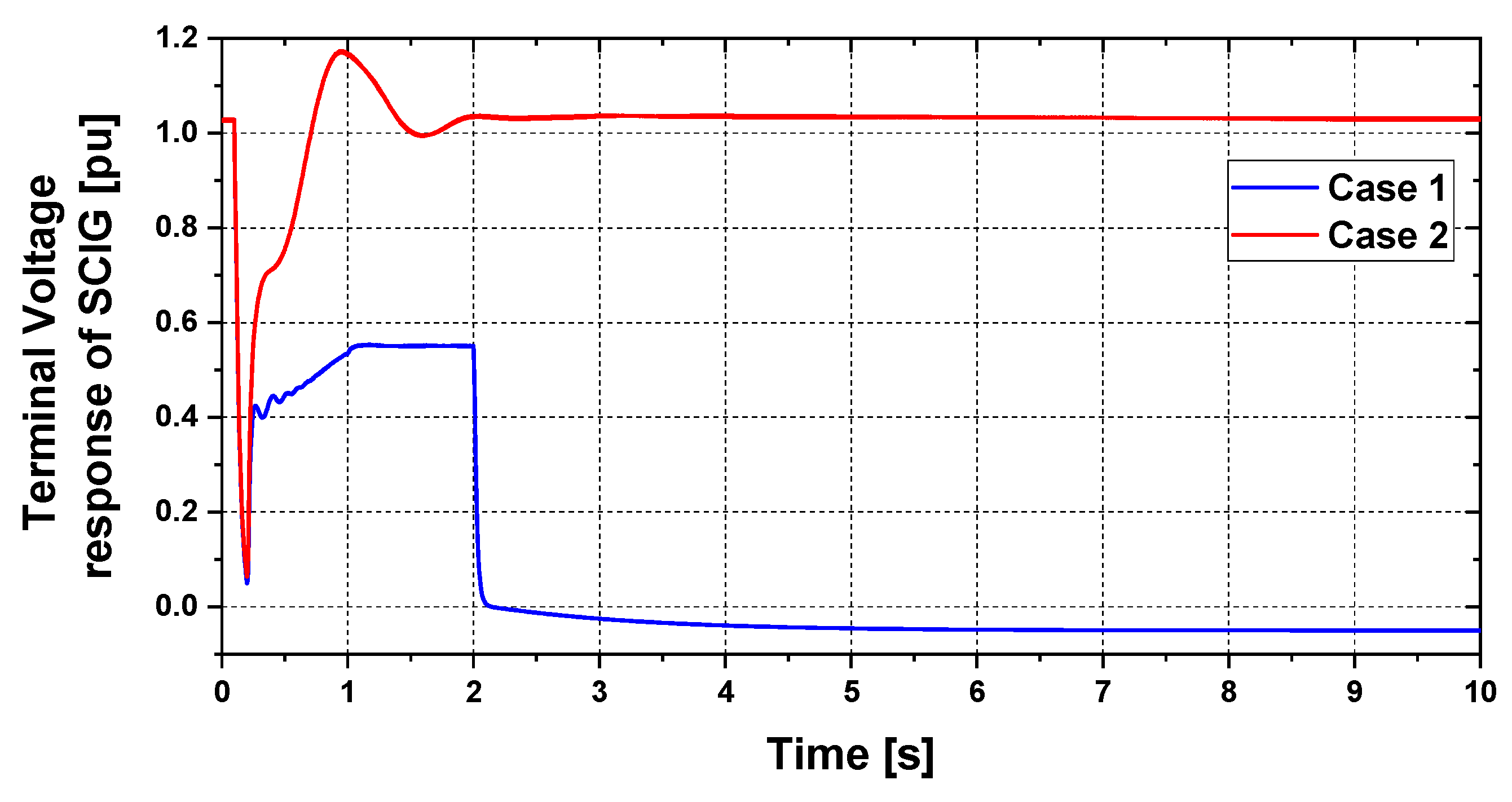
5.1. Transient Stability Analysis

As shown in Figure 1, the triple-line-to-ground (3LG) fault is considered as a network disturbance near Bus 11 at one of the double circuit transmission lines. The fault conditions are presented in Figure 10. The wind speed data applied to the FSWT-SCIG are sustained constantly at 12 m/s based on the supposition that the wind speed does not change often within this short period.
Figure 11 presents the reactive power response of BSS (Case 2), which indicates that it can provide an effective amount of reactive power to the SCIG during transient periods as depicted in Figure 12. Due to this effective injection of reactive power from the BSS, the terminal voltage of the SCIG goes back to the nominal value more quickly in Case 2, whereas it fails in Case 1, as shown in Figure 13. As the terminal voltage does not reach 90% of the nominal value within 1.5 s based on standard grid code [23], it is disconnected from the main power grid by opening the circuit breaker (CB) at 2.0 s. The rotor speed response of the SCIG, as shown in Figure 14, is unstable in Case 1 but is stable in Case 2 after the fault. This is because the SCIG requires more reactive power during transient periods than steady-state periods to improve the air gap flux. If enough reactive power is not provided, the developed electromagnetic torque of the SCIG declines considerably. Thus, the SCIG’s rotor speed increases considerably in Case 1 and makes the whole system unstable. On the other hand, in Case 2 the SCIG gets enough reactive power from the BSS during a network disturbance situation, and therefore its rotor speed response is stable. The real power output of the SCIG is shown in Figure 15. The real power output goes back to the nominal value more effectively in Case 2 than Case 1. Finally, the rotor speed responses of conventional SGs are presented in Figure 16. The rotor speed of SGs are more stable in Case 2 than Case 1. Thus, from the above analysis it is clear that the LVRT capability can be improved by incorporating the proposed BSS.

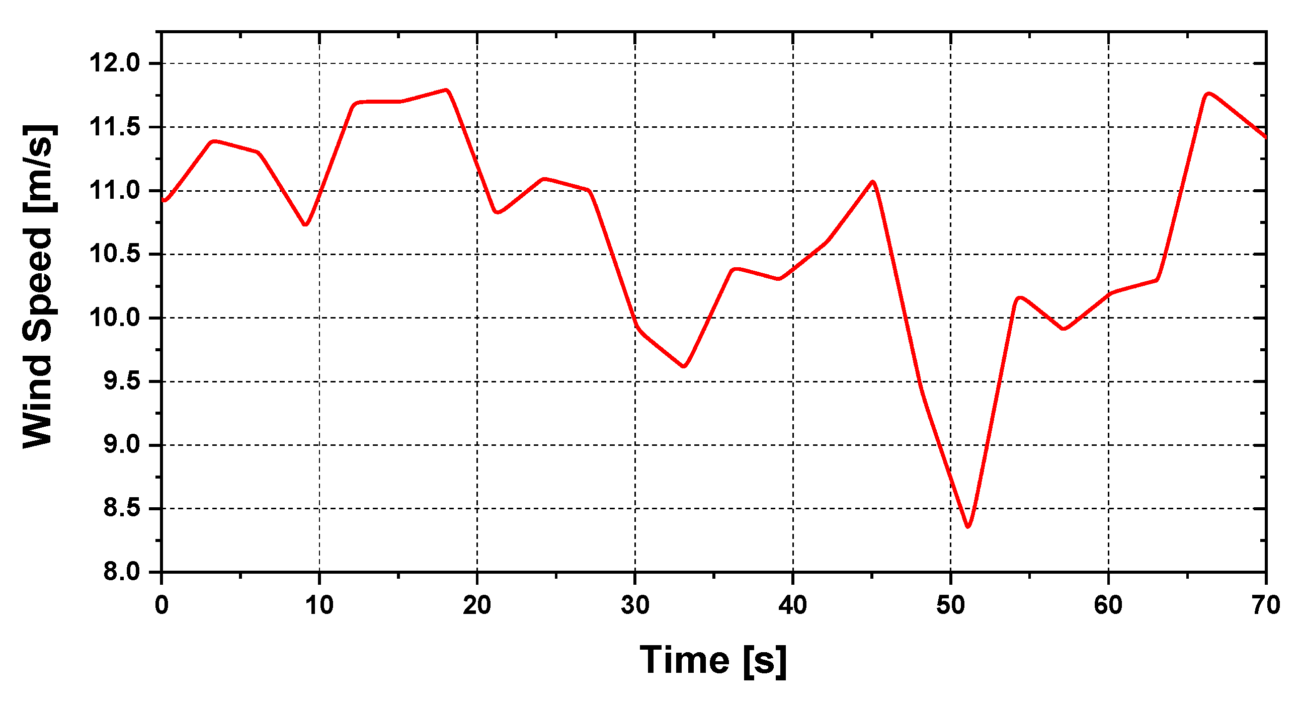
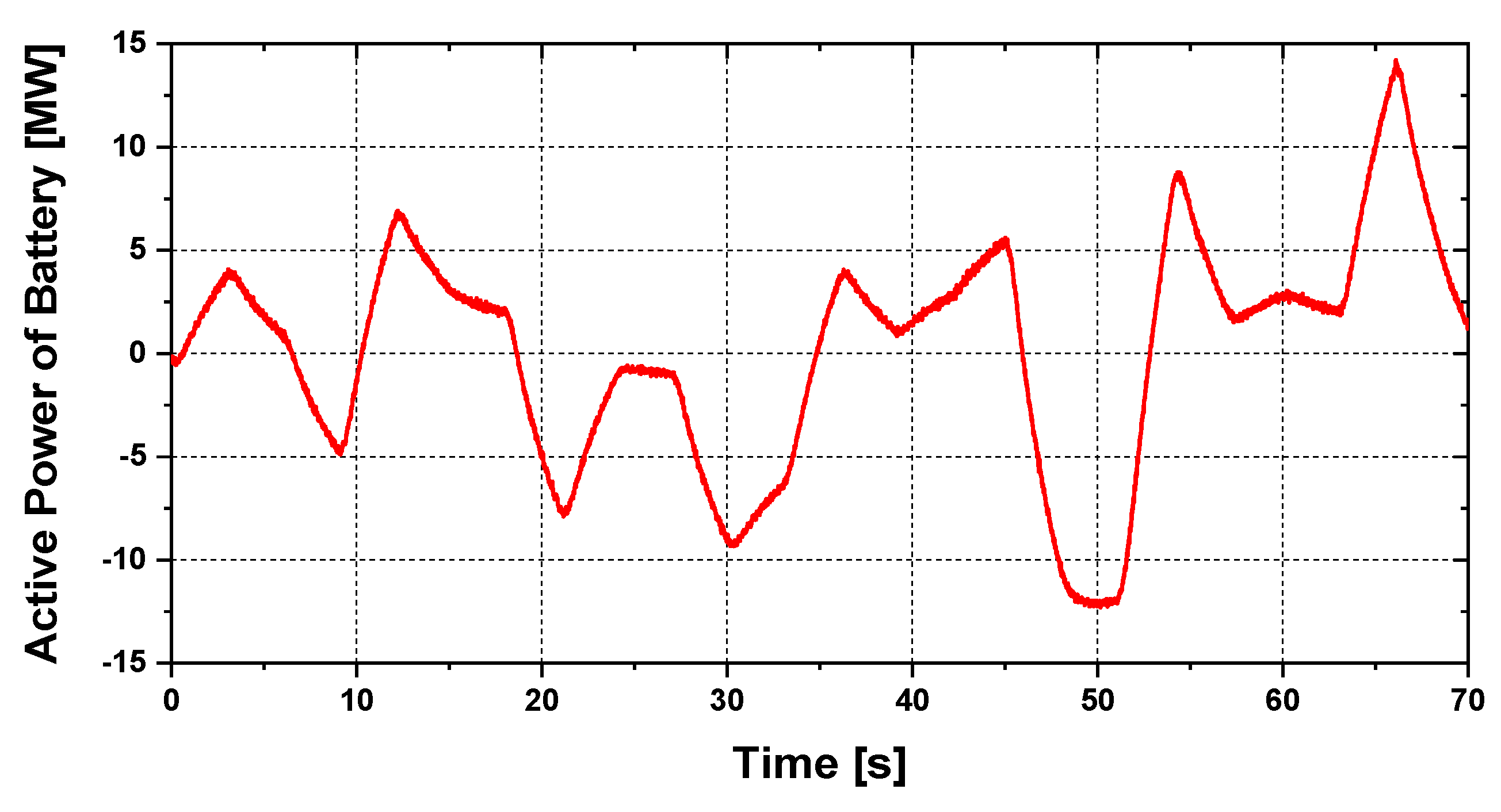
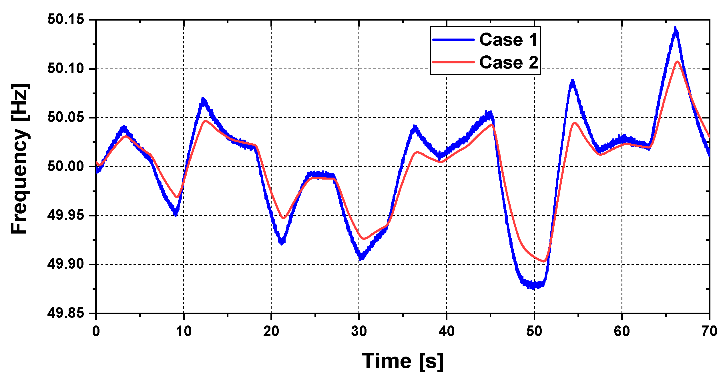
5.2. Steady-State Stability Analysis

The actual wind speed value of Hokkaido Island, Japan is taken in this steady-state analysis as depicted in Figure 17. The total computational time is considered as 70 s.
Figure 18 shows the real power profile of SCIG-based WFs. The responses are identical for both cases, because no control system is involved in the SCIG. Additionally, the real power output is fluctuating because of the variable wind speed data.
The BSS real power profile for Case 2 is presented in Figure 19. From the figure, it is clear that the BSS can ensure an effective amount of real power based on the frequency fluctuations. Thus, the frequency variation is smaller in Case 2 compared to Case 1, as depicted in Figure 20, which validates the importance of the proposed BSS. Figure 21 shows the real power profiles of conventional power plants (SGs). The real power outputs of SGs are fluctuating because of the variable outputs of SCIGs. In addition, there is small variance between the Case 1 and Case 2 responses. This is because BSS is providing and taking real power to and from the grid system, based upon frequency variations.
Finally, Figure 22 presents the mechanical power output of FSWT. The responses are identical for both cases, as no control system is involved in FSWT-SCIGs.
Table 1 shows the +Δf, -Δf, and σ for both cases, which are calculated from Figure 20. The +Δf, -Δf, and σ are smaller in Case 2 compared to Case 1.

6. Conclusions

To augment LVRT aptitude and minimize the frequency oscillations of a hybrid power system during transient and steady-state periods, a novel BSS-based FSWT-SCIG is proposed in this paper. Detailed design procedures of the proposed BSS, WFs, and hybrid power systems are explained adequately. The BSS can provide real and reactive power during steady-state and transient periods, respectively. The proposed BSS is composed of both LVRT enhancement techniques and frequency control algorithms. Different case studies are executed to show the usefulness of the proposed BSS. The LVRT characteristic is determined with respect to the standard grid code, taking a 3LG fault. Steady-state performance is tested using the actual wind speed data of Hokkaido Island, Japan. The simulation results clearly indicate that the LVRT aptitude can be improved, and frequency oscillations can be minimized effectively, by using the proposed BSS. Therefore, this proposed control technique has an encouraging prospective value.
As future work, the variable droop controller techniques of BSS with FSWT-SCIGs will be a strong candidate.

Author Contributions

M.R.H. and E.J. prepared the theoretical conceptions, and designed the proposed BSS and model of hybrid power system. M.R.H. executed the simulation studies. M.R.H. and E.J. wrote the manuscript. All authors have read and agreed to the published version of the manuscript.

Funding

This research received no external funding.

Conflicts of Interest

The authors declare no conflict of interest.

Appendix A

The parameters of conventional SGs and SCIGs are depicted in Table A1 and Table A2, respectively.
Table A1. SGs parameters.
ParameterSG1 (Thermal) SG2 (Thermal) SG3 (Hydro)
Voltage16.5 kV18 kV13.8 kV
Ra0.003 pu0.003 pu0.003 pu
Xl0.1 pu0.1 pu0.1 pu
Xd2.11 pu2.11 pu1.20 pu
Xq2.05 pu2.05 pu0.700 pu
X’d0.25 pu0.25 pu0.24 pu
X’’d0.21 pu0.21 pu0.20 pu
X’’q0.21 pu0.21 pu0.20 pu
T’do6.8 s7.4 s7.2 s
T’’do0.033 s0.033 s0.031 s
T’’qo0.030 s0.030 s0.030 s
H4.0 s4.0 s4.0 s
Table A2. SCIG parameters.
Squirrel Cage Induction Generator (SCIG)
R10.01 pu
X10.1 pu
Xm3.5 pu
R210.035 pu
R220.014 pu
X210.03 pu
X220.089 pu
H1.5 s

References

  1. Ula, A.H.M.S. Global warming and electric power generation: What is the connection? IEEE Trans. Energy Convers. 1991, 6, 599–604. [Google Scholar] [CrossRef]
  2. Global Status Report 2017. Available online: https://www.worldgbc.org/sites/default/files/UNEP%20188_GABC_en%20%28web%29.pdf (accessed on 10 January 2020).
  3. Global Wind Energy Council (GWEC). Annual Market Update 2015, Global Wind Report 2015. Available online: http://www.gwec.net/ (accessed on 15 October 2017).
  4. Global Wind Energy Council (GWEC). Global Wind Energy Outlook 2016: Wind Power to Dominate Power Sector Growth 2016. Available online: http://www.gwec.net/ (accessed on 25 November 2019).
  5. Hazari, M.; Mannan, M.; Umemura, A.; Takahashi, R.; Tamura, J. Stabilization of Wind Farm by Using PMSG Based Wind Generator Taking Grid Codes into Consideration. J. Power Energy Eng. 2018, 6, 40–52. [Google Scholar] [CrossRef] [Green Version]
  6. Priyavarthini, S.; Nagamani, C.; Ilango, G.S.; Rani, M.A.A. An improved control for simultaneous sag/swell mitigation and reactive power support in a grid-connected wind farm with DVR. Int. J. Electr. Power Energy Syst. 2018, 101, 38–49. [Google Scholar] [CrossRef]
  7. Mohammadpour, H.A.; Ghaderi, A.; Mohammadpour, H.; Ali, M.H. Low voltage ride-through enhancement of fixed-speed wind farms using series FACTS controllers. Sustain. Energy Technol. Assess. 2015, 9, 12–21. [Google Scholar] [CrossRef]
  8. Wei, Y.; Kang, L.; Qi, R.; Wen, M.; Cheng, M.M. Optimal control of SVC-MERS and application in SCIG powered micro-grid. In Proceedings of the 2014 IEEE Applied Power Electronics Conference and Exposition—APEC 2014, Fort Worth, TX, USA, 16–20 March 2014; pp. 3367–3373. [Google Scholar]
  9. Gatavi, E.; Hellany, A.; Nagrial, M.; Rizk, J. Improved Low Voltage Ride-Through capability of DFIG-based wind turbine with breaking resistor and converter control. In Proceedings of the 2018 IEEE 12th International Conference on Compatibility, Power Electronics and Power Engineering (CPE-POWERENG 2018), Doha, Qatar, 10–12 April 2018; pp. 1–6. [Google Scholar]
  10. Kamel, R.M. Three fault ride through controllers for wind systems running in isolated micro-grid and Effects of fault type on their performance: A review and comparative study. Renew. Sustain. Energy Rev. 2014, 37, 698–714. [Google Scholar] [CrossRef]
  11. Marei, M.I.; El-Goharey, H.S.K.; Toukhy, R.M. Fault ride-through enhancement of fixed speed wind turbine using bridge-type fault current limiter. J. Electr. Syst. Inf. Technol. 2016, 3, 119–126. [Google Scholar] [CrossRef] [Green Version]
  12. Heydari-doostabad, H.; Khalghani, M.R.; Khooban, M.H. A novel control system design to improve LVRT capability of fixed speed wind turbines using STATCOM in presence of voltage fault. Int. J. Electr. Power Energy Syst. 2016, 77, 280–286. [Google Scholar] [CrossRef]
  13. Ren, J.; Hu, Y.; Wang, J.; Ji, Y. Principle of low voltage ride-through ability realization of fixed speed wind generator using series reactor and SVC. In Proceedings of the 7th International Power Electronics and Motion Control Conference, Harbin, China, 2–5 June 2012; Volume 3, pp. 2173–2177. [Google Scholar]
  14. Kalsi, S.; Madura, D.; Howard, R.; Snitchler, G.; MacDonald, T.; Bradshaw, D.; Grant, I.; Ingram, M. Superconducting dynamic synchronous condenser for improved grid voltage support. In Proceedings of the 2003 IEEE PES Transmission and Distribution Conference and Exposition (IEEE Cat. No.03CH37495), Dallas, TX, USA, 7–12 September 2003; Volume 2, pp. 742–747. [Google Scholar]
  15. Farias, M.F.; Battaiotto, P.E.; Cendoya, M.G.; de Ingeniería, F. Investigation of UPQC for sag compensation in wind farms to weak grid connections. In Proceedings of the 2010 IEEE International Conference on Industrial Technology, Vina del Mar, Chile, 14–17 March 2010; pp. 937–942. [Google Scholar]
  16. Mahela, O.P.; Gupta, N.; Khosravy, M.; Patel, N. Comprehensive Overview of Low Voltage Ride Through Methods of Grid Integrated Wind Generator. IEEE Access 2019, 7, 99299–99326. [Google Scholar] [CrossRef]
  17. He, G.; Chen, Q.; Kang, C.; Xia, Q.; Poolla, K. Cooperation of Wind Power and Battery Storage to Provide Frequency Regulation in Power Markets. IEEE Trans. Power Syst. 2017, 32, 3559–3568. [Google Scholar] [CrossRef]
  18. Nguyen, C.L.; Lee, H.H. A Novel Dual-Battery Energy Storage System for Wind Power Applications. IEEE Trans. Ind. Electron. 2016, 63, 6136–6147. [Google Scholar] [CrossRef]
  19. Kundur, P. Power System Stability & Control; McGraw-Hill Inc.: New York, NY, USA, 1994. [Google Scholar]
  20. Rosyadi, M.; Umemura, A.; Takahashi, R.; Tamura, J.; Uchiyama, N.; Ide, K. Simplified Model of Variable Speed Wind Turbine Generator for Dynamic Simulation Analysis. IEEJ Trans. Power Energy 2015, 135, 538–549. [Google Scholar] [CrossRef]
  21. Muyeen, S.M.; Tamura, J.; Murata, T. Stability Augmentation of a Grid Connected Wind Farm; Springer: London, UK, 2009. [Google Scholar]
  22. Hazari, M.R.; Mannan, M.A.; Muyeen, S.M.; Umemura, A.; Takahashi, R.; Tamura, J. Stability Augmentation of a Grid-Connected Wind Farm by Fuzzy-Logic-Controlled DFIG-Based Wind Turbines. Appl. Sci. 2018, 8, 20. [Google Scholar] [CrossRef] [Green Version]
  23. E. ON NETZ GmbH. Grid Connection Regulation for High and Extra High Voltage; E. ON NETZ GmbH: Essen, Germany, 2006. [Google Scholar]
Figure 1. Model of hybrid power system.
Electronics 09 00239 g001
Figure 2. Exciter model of synchronous generators (SGs).
Electronics 09 00239 g002
Figure 3. Governor model of thermal turbine.
Electronics 09 00239 g003
Figure 4. Governor model of hydro turbine.
Electronics 09 00239 g004
Figure 5. Automatic generation control (AGC).
Electronics 09 00239 g005
Figure 6. Cp vs. λ characteristics curve.
Electronics 09 00239 g006
Figure 7. Pitch controller of fixed speed wind turbine-squirrel cage induction generator (FSWT-SCIG).
Electronics 09 00239 g007
Figure 8. Proposed battery storage system (BSS).
Electronics 09 00239 g008
Figure 9. Proposed control strategy of BSS.
Electronics 09 00239 g009
Figure 10. Triple-line-to-ground (3LG) fault conditions.
Electronics 09 00239 g010
Figure 11. Reactive power response of BSS (Case 2).
Electronics 09 00239 g011
Figure 12. Reactive power response of SCIG.
Electronics 09 00239 g012
Figure 13. Terminal voltage response of SCIG.
Electronics 09 00239 g013
Figure 14. Rotor speed response of SCIG.
Electronics 09 00239 g014
Figure 15. Real power response of SCIG.
Electronics 09 00239 g015
Figure 16. Rotor speed response of SGs.
Electronics 09 00239 g016
Figure 17. Wind speed applied to FSWT-SCIG.
Electronics 09 00239 g017
Figure 18. Real power response of FSWT-SCIG.
Electronics 09 00239 g018
Figure 19. Real power output of BSS (Case 2 only).
Electronics 09 00239 g019
Figure 20. Hybrid power system frequency response.
Electronics 09 00239 g020
Figure 21. Real power response of SGs.
Electronics 09 00239 g021
Figure 22. Mechanical power output of FSWT.
Electronics 09 00239 g022
Table 1. Comparison of different parameters of the frequency response graph.
Parameters of frequencyCase 1Case 2
Maximum frequency deviation in positive direction (+Δf)0.14280.1072
Maximum frequency deviation in negative direction (−Δf)−0.1249−0.0969
Standard deviation (σ)0.05360.0419

