Fuzzy-Based Thermal Management Scheme for 3D Chip Multicores with Stacked Caches

1
College of Electronic and Information Engineering, Nanjing University of Aeronautics and Astronautics, Nanjing 211106, China
2
Jincheng College, Nanjing University of Aeronautics and Astronautics, Nanjing 211156, China
3
School of Electrical and Electronic Engineering, Anhui Science and Technology University, Chuzhou 233100, China
*
Author to whom correspondence should be addressed.
Electronics 2020, 9(2), 346; https://0-doi-org.brum.beds.ac.uk/10.3390/electronics9020346
Submission received: 1 February 2020
/
Revised: 13 February 2020
/
Accepted: 15 February 2020
/
Published: 18 February 2020
(This article belongs to the Special Issue Low-Power Techniques for Embedded Systems and Network-on-Chip Architectures)
Abstract
:By using through-silicon-vias (TSV), three dimension integration technology can stack large memory on the top of cores as a last-level on-chip cache (LLC) to reduce off-chip memory access and enhance system performance. However, the integration of more on-chip caches increases chip power density, which might lead to temperature-related issues in power consumption, reliability, cooling cost, and performance. An effective thermal management scheme is required to ensure the performance and reliability of the system. In this study, a fuzzy-based thermal management scheme (FBTM) is proposed that simultaneously considers cores and stacked caches. The proposed method combines a dynamic cache reconfiguration scheme with a fuzzy-based control policy in a temperature-aware manner. The dynamic cache reconfiguration scheme determines the size of the cache for the processor core according to the application that reaches a substantial amount of power consumption savings. The fuzzy-based control policy is used to change the frequency level of the processor core based on dynamic cache reconfiguration, a process which can further improve the system performance. Experiments show that, compared with other thermal management schemes, the proposed FBTM can achieve, on average, 3 degrees of reduction in temperature and a 41% reduction of leakage energy.
1. Introduction
With the development of semiconductor technology, the performance of microprocessors has been improved by increasing the density of on-chip transistors and enabling the presence of more cores on a single die. Multiple cores are integrated onto a single chip that needs a high number of caches to supply enough memory bandwidth, which is expected to exacerbate the existing ‘memory wall’ issue [1]. with the use of through-silicon-vias (TSV), three-dimensional (3D) integration is a good choice to stack large memory as a last-level on-chip cache directly on the top of logic cores, which can improve system performance by reducing cache misses and off-chip access. Along with the size of cache increase, the access latency highly depends on the diatance traversed along with the chip. Therefore the non-uniform cache architecture (NUCA) has become more attractive [2]. The last-level on-chip cache is separated into a number of small cache banks, with the data access latency relying on the physical path to the cores.
However, as is well known, increasing the number of cores and cache layers may cause a drastic increase in power density, which leads to temperature-dependent issues in system performance, reliability, and cooling costs [3]. Therefore, an effective thermal management scheme is required to ensure the performance and reliability of the system.
To prevent such a detrimental impact of high temperature, there has been a significant amount of work on dynamic thermal management (DTM). DTM mechanisms are utilized to control the peak temperature of the system by reducing the power consumption of the hot spot during the runtime. Much research on DTM has utilized dynamic voltage and frequency scaling (DVFS) as an important tool to control power consumption. DVFS provides a linear performance drop with a cubic reduction in dynamic power consumption, assuming that voltage scales proportionally to frequency. Meng [4] presented a novel optimized policy to choose voltage–frequency settings for the execution mode of each core by utilizing predictions on a regression model while maintaining power and temperature constraints. Our prior work [5] presented a thermal-aware policy of dynamic frequency scaling bus (DFSB) for 3D Network-on-Chip (NoC) hybrid architectures. However, the DVFS-based thermal management system is an open-loop control system that requires accurate power measurement and limits the stability of the system.
A large portion of work on DTM only focuses on core-level techniques, but this is not sufficient because on-chip caches also play an important role in improving the performance of systems. Much literature has reported that on-chip caches are a major power dissipating source. It has been reported that the power portion of on-chip caches reaches up to 50% of the total power consumption of a microprocessor system [6]. Additionally, on-chip caches have a substantial impact on chip temperature and should be seriously considered as a target for thermal management. Leakage power consumption, especially, is the most important challenge among temperature-related problems because a higher power density leads to an increase of chip temperature. An effective way to reduce the leakage power consumption of on-chip caches is by shrinking size. A shrinking cache can bring down leakage power consumption obviously, but a random reduction cache may degrade system performance. The dynamic cache reconfiguration (DCR) technique is an effective way to bring down cache power consumption by adjusting cache configurations according to the application characteristics at runtime. Sun [7] proposed a performance-cognizant thermal efficient technique to monitor the size of the cache banks in order to reduce power consumption and lower temperature. However, this technique is not an optimal solution because it cannot consider both cache and processor power consumption together.
The above works on thermal management focused on either processor cores or stacked caches. Wang [8] proposed an approach to integrate processor voltage scaling and cache reconfiguration together to minimize system energy consumption. However, this approach ignored system temperature.
To overcome the abovementioned issue, this paper presents a fuzzy-based thermal management scheme (FBTM) that simultaneously considers the power consumption of cores and stacked caches. The fuzzy-based thermal management includes a dynamic cache reconfiguration scheme and a fuzzy-based control policy. The dynamic cache reconfiguration scheme is introduced to adjust the size of cache of every core according to application characteristics in order to minimize power consumption. The fuzzy-based control policy is used to adjust the frequency level of cores based on dynamic cache reconfiguration, which can further improve system performance. In addition, the fuzzy-based control policy does not require detailed knowledge of the system.
The contributions of this paper are as follows.
- (1)
- We consider the impact of the power consumption of cores and on-chip caches in parallel in this modeling for the first time.
- (2)
- We propose a fuzzy-based control policy that is based on fuzzy logic and it keeps low design and complexity.
- (3)
- This is the first work that orchestrates the thermal management of cores and dynamic cache reconfiguration at the same time by considering application characteristics.
The rest of this paper is organized as follows. Section 2 describes the model of the 3D-stacked NUCA cache architecture. Section 3 shows the design of the proposed fuzzy-based thermal management scheme in detail. Experiment results and comparisons are discussed in Section 4. Section 5 shows the concluding remarks.
2. System Model
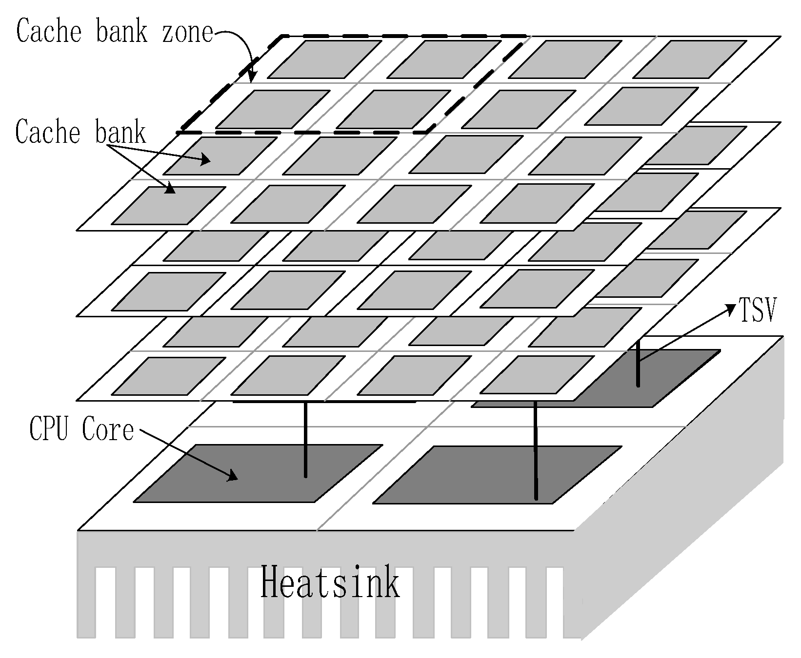
A 3D-stacked NUCA cache architecture [7] consisting of multiple layers of stacked caches and a single layer of processor cores is shown in Figure 1. We assumed that the core layer that was closeted to the heat sink consisted of four processor cores and every cache layer had 16 cache banks. The interlayer core-based distribution cache way placement in [7] was used to divide the banks into four zones, and the area of the cache zone was equal to the core. Every cache zone had four cache banks, and the quantity of cache zones was equivalent to the quantity of cores. With the TSVs, the core had the same access latency as the cache zones in different cache layers right above the core.
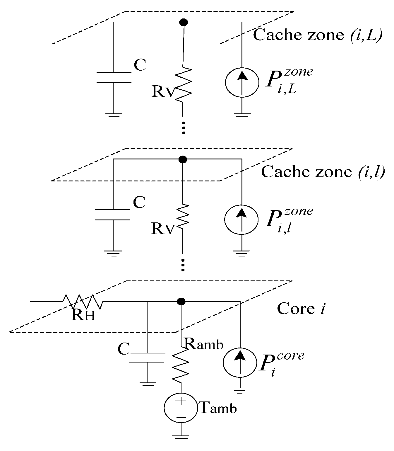
The thermal model of 3D-stacked NUCA cache architecture was adapted from [9], and each core or cache zone was represented as a thermal model component in this thermal model. For better electrical characteristics in 3D integrated circuits, the thickness of a silicon layer is exceedingly small, from only 5 to 50 , while the processor often spans over one millimeter [10]. Hence, vertical nodes have mutual thermal couplings stronger than those of the horizontal nodes, and 90% of the heat is transferred vertically from the silicon to the heatsink [11]. When applying the thermal model in [9], the core had a close thermal relationship with the cache zones right above the core. Therefore, we intuitively regarded the core and the cache zones directly above the core as a super-core. The thermal model of a super-core is shown in Figure 2. For Figure 2, we assumed that there were L cache layers and the cache zone directly above the core i and located in l cache layer was a cache_zone(i,l). The temperature of the core and cache zone can be calculated as follows:
where and represent the temperature of cache_zone(i,l) and core i, is the thermal resistance between the core and the ambient environment, is the thermal resistance between different cache zones in adjacent layers, is the ambient temperature, and and are the power consumptions of cache_zone(i,l) and core i, respectively. In Equation (2), becomes Pgated, which is a very small quantity of leakage power consumption, when cache_zone(i,l) is inactivated.
The core power consumption consists of dynamic power consumption and leakage power consumption. The dynamic power consumption is the power that is caused by the charging and discharging of capacitances, and the leakage power consumption is the power that is caused by the current leakage of the circuits. The core power consumption can be calculated as follows:
where is the supply voltage, f is the clock frequency, C is the switch capacitance, and is the switching activity. For leakage power, is the leakage current, T is the temperature, and A, B, ,, , and are all the parameters that rely on chip technology.
3. Proposed Thermal Management Scheme
It is worth noting that the power consumption of a cache zone is related to whether the cache banks of the cache zone are activated, and A, B, ,, , and are all the parameters that rely on chip technology and which are tough mathematically model beforehand. In addition, there is a feedback loop between the leakage power consumption and temperature in Equation (3). When one designs a thermal management scheme, one must consider the feedback loop. If not, thermal control quality may be affected.
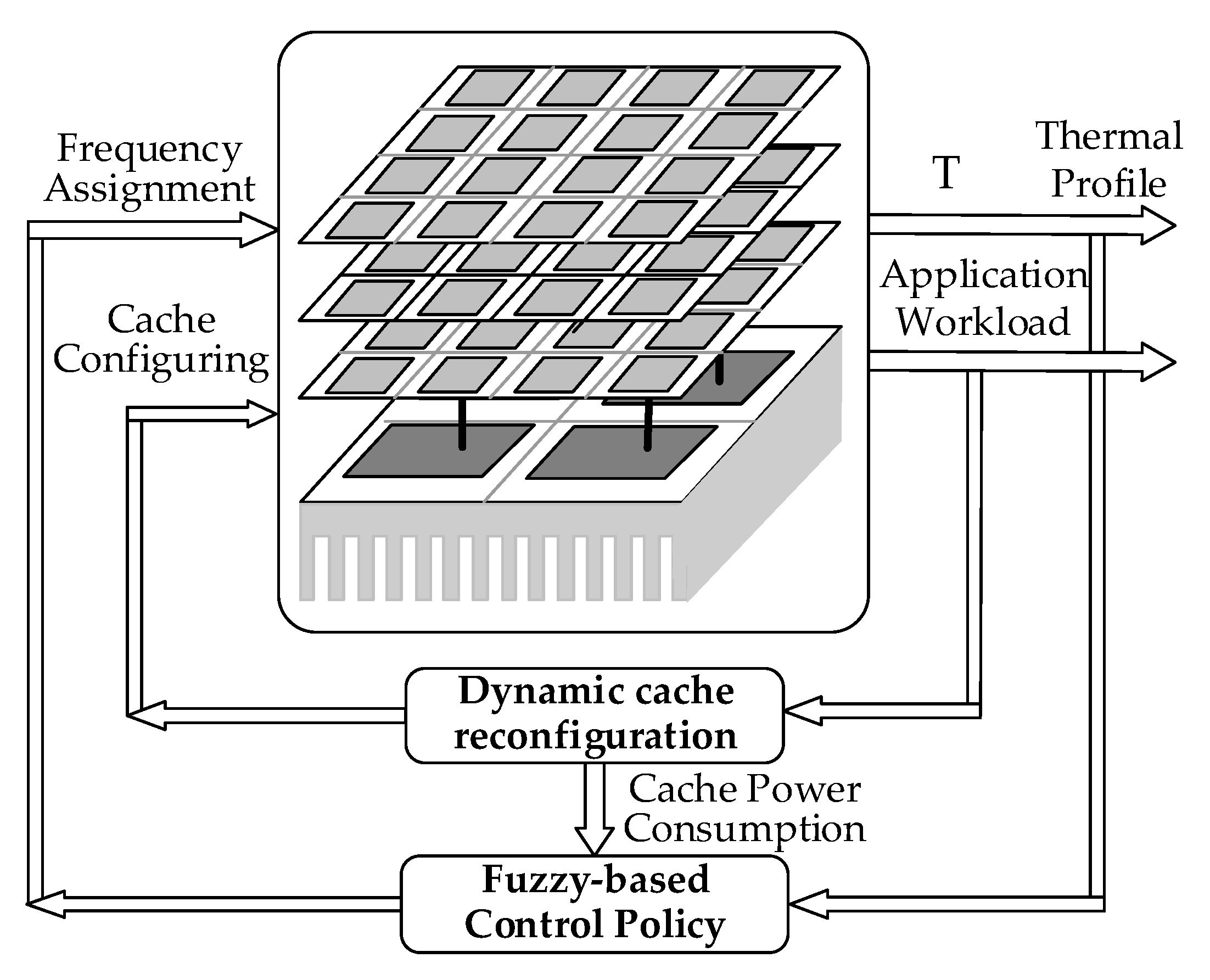
We tried to solve the issue through a combined fuzzy-based thermal management scheme that did not depend on a precise system model and that simultaneously considered the power consumption of cores and stacked caches. The proposed thermal management scheme is shown in Figure 3. On-chip caches play an essential role in improving system performance, which consumes a large portion of system power. The dynamic cache reconfiguration scheme determines the size of the cache for the processing core according to the application that reaches a substantial amount of power consumption savings. Each core has a fuzzy logic controller that manages one super-core. Based on fuzzy logic rules, the fuzzy-based control policy adjusts the frequency level of the cores, a process that can further improve system performance.
3.1. Dynamic Cache Reconfiguration Scheme
The applications running on the cores are classified into two types, memory-intensive and computation-intensive, which have different requirements for cache size. This characteristic motivated us to resize the cache according to their application. In addition, leakage power consumption is more intensive than dynamic power consumption for on-chip cache. Leakage power consumption always exists as long as the power is supplied to the cache bank, while the dynamic power consumption is only consumed during the cache block accesses. Hence, saving leakage power consumption is useful, and turning off some cache banks can aid this saving.
After observation, we found that if a memory-intensive application has a smaller size of cache than needed, the applications will have more cache misses. If we shrink the size of the LLC cache while the cache miss rate of the application is under a permissible degradation percentage, the performance remains the same. However, the power consumption is reduced by disabling some cache banks.
The aim of a dynamic cache reconfiguration scheme is to shut off as many cache banks as possible while the cache miss rate is not increasing so that the system performance remains the same. Therefore, a cache miss rate predictor, which predicts the cache miss rate before and after closing some cache banks, is needed in the cache controller. That means that is the cache miss rate is under a permissible degradation percentage, some cache banks are shut off.
For the cache miss rate predictor, we used the shadow tags that were suggested by Sun [7]. The shadow tags work similarly to normal cache tags that contain one more state bits, called gating bits, to show whether the cache line is disabled. A counter is needed to record the number of cache misses of the shadow tags during a period. The counter is periodically reset to zero to observe the runtime cache miss rate. By using shadow tags, the detailed procedure can be formulated as Algorithm 1, which is described in Table 1.
In the 3D-stacked NUCA cache architecture, the core layer is closest to the heat sink, which means that cache banks of different cache layers have different thermal dissipation values. Consequently, the cache banks in the cache layer away from the heat sink have the precedency to shut down. The input of Algorithm 1 is the application workload. The application is run for some interval before the cache reconfiguration process starts. First, all the cache banks are turned on, and the cache banks that are far away from the heat sink have higher priorities for being power gated. After gating, the miss rate is predicted by updating the shadow tags. Then, the predicted miss rate is compared to the current miss rate without gating the cache bank. If the miss rate is not increased much, the real cache bank is gated. The cache reconfiguration is repeated, and it can continue as long as the performance does not degrade beyond a predefined limit. We also put an additional restriction on the maximum number of banks that can be turned off. The output of Algorithm 1 is the reconfigured cache. By disabling some cache banks, the leakage power that is consumed by the cache bank is saved.
3.2. Fuzzy-Based Control Policy
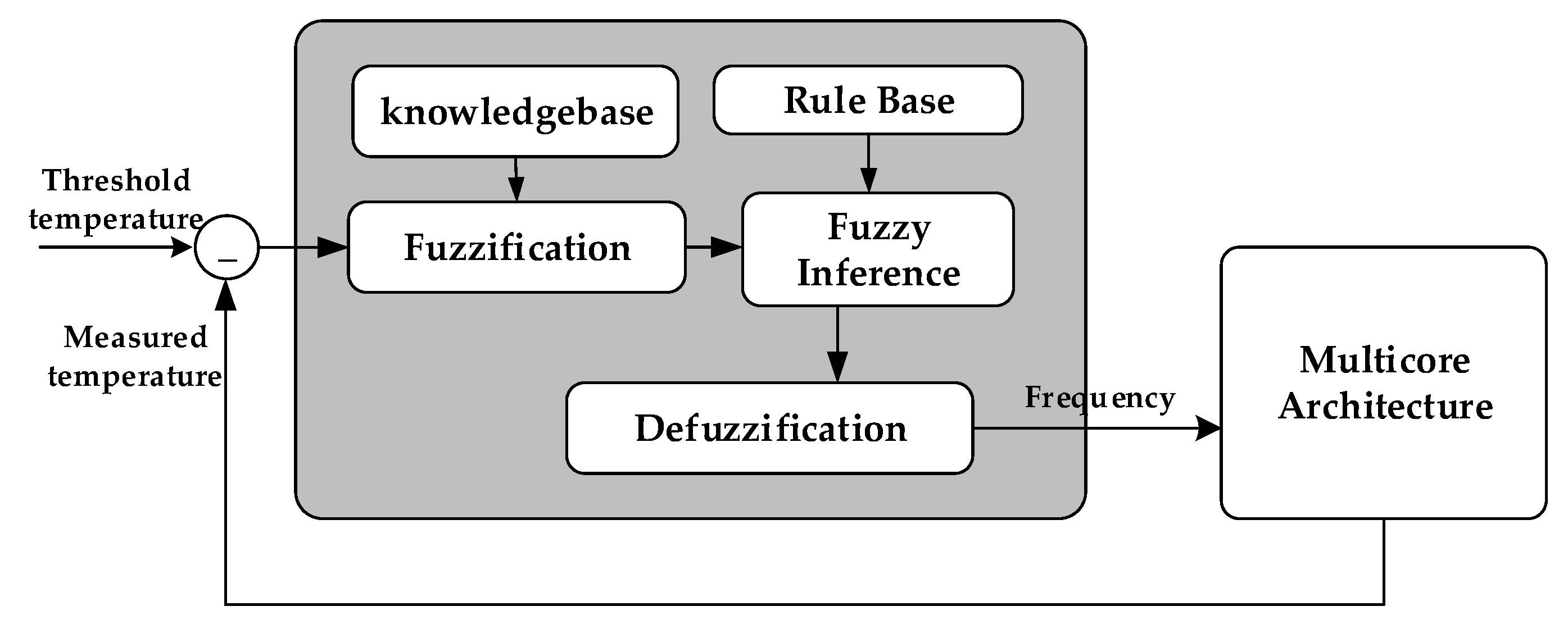
Due to the complexity of the thermal model, we adopted a fuzzy-based control policy. The main idea of the proposed policy was to take advantage of fuzzy logic to avoid the establishment of analytical models between the input and output parameters. The proposed policy based on fuzzy logic in a closed-loop is shown in Figure 4.
The fuzzy-based control policy involves input and output variables identification, the fuzzy membership functions of the input and output, and the fuzzy rules and defuzzification of the fuzzy rule outputs.
- (1)
- Input and Output:
By Fourier’s Law, the change of temperature can be calculated as follows [12]:
where R is the thermal resistance and C is the thermal capacitance, respectively, and and are the temperature and power consumption at time t. If the initial temperature and steady-state temperature be and , then can be derived as
By using derivative analysis to extract a recursive formula, temperature change rate at time can be shown as the following:
By using this equation, the temperature change rate at the time can be shown as the following:
Suppose the temperature control interval be ; then, the temperature for the next sampling period can be formulated as
The goal of the design was to limit the temperature near the threshold temperature Tth. The difference between threshold temperature and measured temperature can be formulated as
Thus, one of the input parameters is the difference value between the threshold temperature and the measured temperature , and another input parameter is the change rate of temperature . The output parameter is the frequency of the core after the normalization of the highest frequency of the whole system. At each sampling period, the controller monitors the difference value , predicts the direction of temperature change by , and adjusts the frequency of the processor core.
- (2)
- The Fuzzy Membership Functions:
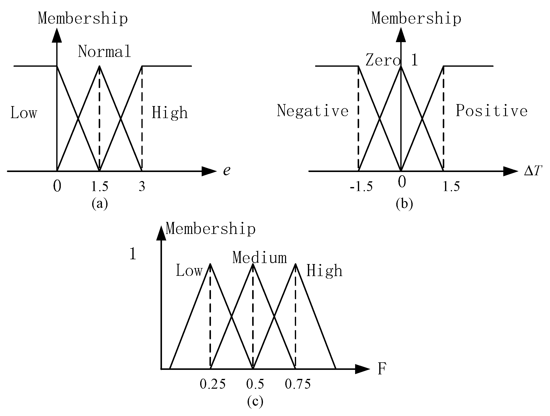
The fuzzy membership functions are shown in Figure 5. Every input linguistic variable has three values that can cover all essential situations, and we used the symmetric triangular function, which is a frequently-used type of the membership function.
We set the searching ranges for and . The searching range of was set to [0,3], which was compared with the threshold temperature that was allowed by the system. The searching range of was set to [-1.5, 1.5]. We could get the parameters through simulation by using HotSpot [13]. In a simulation, the initial temperature is set to be the same as the ambient temperature, and the power profile is the highest possible power consumption of the system. During the simulation, the highest temperature rising rate should be and the difference value between the threshold temperature and the peak temperature should be .
- (3)
- The Fuzzy Logic Rules:
The fuzzy logic rules were designed by knowledge that allowed the temperature of the super-core to remain around the threshold temperature. Table 2 shows the fuzzy rules, which were designed by the commonsense of the people. A low thermal error means that the temperature is relatively near the threshold temperature. Then, positive and zero thermal change rates may cause the temperature to exceed the threshold temperature. The high-frequency level may be set in the next time period. A high thermal error means that the temperature is below the threshold temperature. Then, negative and zero thermal change rates mean that the temperature barely increases. A low-frequency level may be set in the next time period. When the thermal error is normal, a positive thermal change rate may bring a high-frequency level, while a negative thermal change rate may bring a low-frequency level.
- (4)
- Defuzzification of Fuzzy Rule Outputs:
Based on the fuzzy logic rules and fuzzified input parameters, we adopted the mean-of-maxima method for the defuzzification and conversion of the output into a frequency ratio of the processor. The membership function of the output F is shown in Figure 5.
4. Experimental Evaluation
In our experiment, a 3D-stacked NUCA cache architecture consisting of four cores with three L2 cache layers was used. Every core had a 32KB L1 instruction cache and a 32KB L1 data cache. Four cache banks were formed into a cache zone, and these were stacked right above each core. The capacity of the cache bank was based on the area of the core. In this experiment, the capacity of every cache bank that was computed by CACTI [14] was 256 KB.
In order to validate the efficacy of our proposed thermal management scheme, HotSpot was used as the thermal simulation platform for multicore processors. We used the SPEC CPU2006 suit [15] on the multicore processor to test the system performance. In the experiment, we used multiprogrammed workloads consisting of four applications. The applications were selected from SPEC CPU2006 benchmark suites. Base on the memory demand of the application, we classified the applications into three sets: the compute-intensive set, the medium set, and the memory-intensive set, as listed in Table 3.
The full system simulator GEM5 [16], which allows for the simulation of multi-processor systems, was used in this experiment. GEM5 includes a Ruby memory model that can simulate memory systems. The GEM5 and McPAT [17] simulation platforms were used to calculate the power consumption in this paper. The change of temperature and the power consumption were simulated in unit intervals called control steps. GEM5 generated the performance trace within the control steps and transmitted it to McPAT. McPAT calculated the power consumption via the performance trace and transmitted the power trace to HotSpot, which is a grid-based thermal modeling tool.
In the experiments, we used three different methods of thermal management for comparison. First, we adopted a DVFS technique that was proposed in [18] as the base method of the experiments, and this was denoted as the baseline. Second, we used the fuzzy-based control policy without a dynamic cache reconfiguration module, and this was denoted as the FLC. Finally, we adopted our proposed thermal management that used a fuzzy-based control policy and dynamic cache reconfiguration module, and this was denoted as the FBTM.
In this work, we adopted a thermal threshold that was not a settled thermal threshold. Instead, it was a thermal threshold that changed during the runtime, as mentioned in [19]. In Algorithm 1, the parameter T was set to 2M clock cycles, and the allowable degradation percentage in cache miss rate was set to 3%.
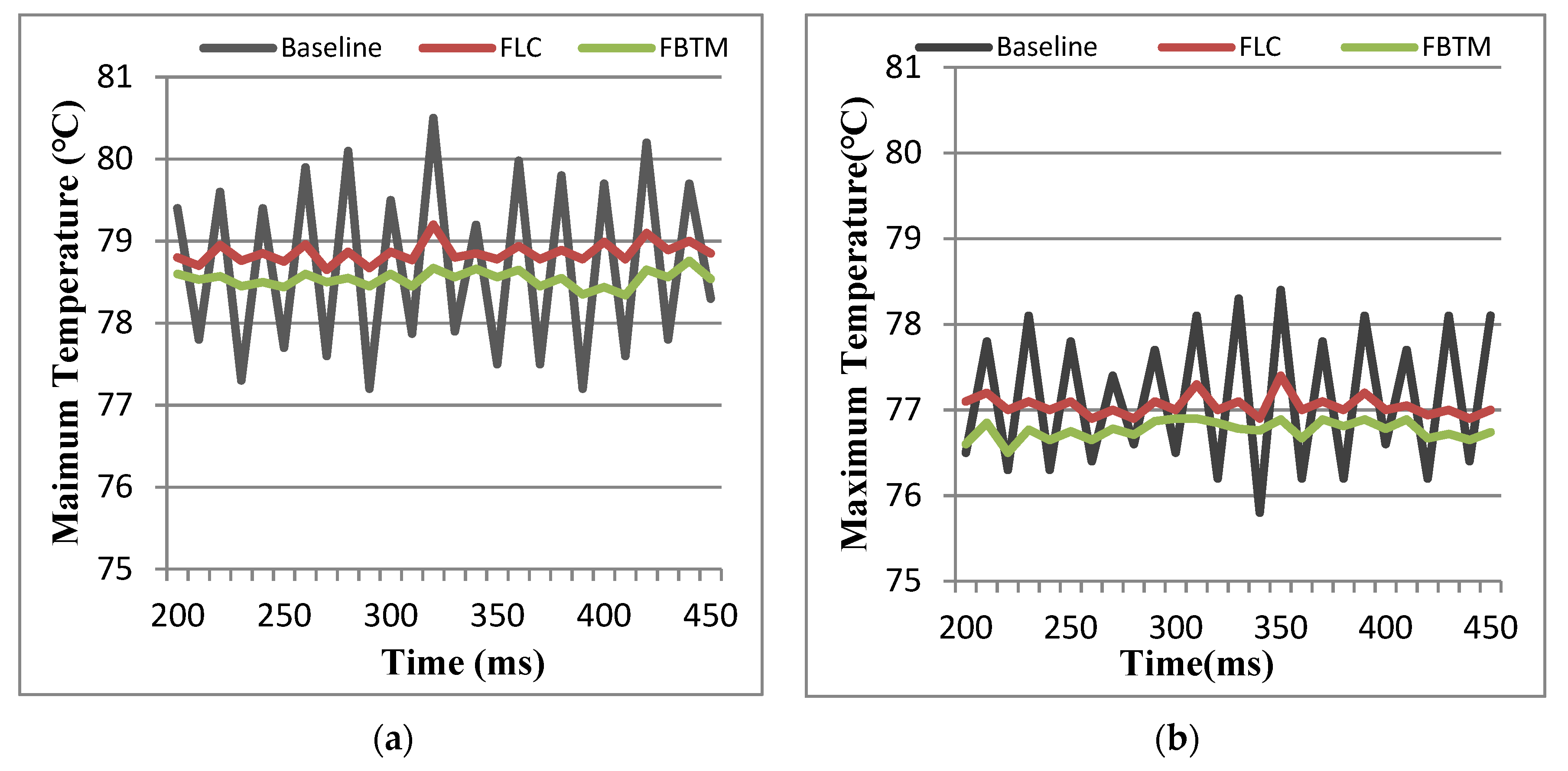
The transient maximum temperature curves while executing mem2 and com2 program sets are shown in Figure 6. The results show that the transient maximum temperature curves of the FLC and the FBTM were steadier than the baseline. From Figure 6, we can observe that the temperature of the baseline fluctuated faster near the threshold temperature, and its fluctuation could be as large as 3.5 degrees. By contrast, the FLC and the FBTM could stably control to the volatility within 0.5 degrees, achieving about 3 degrees of temperature reduction. This was due to the baseline considering too little information and ignoring feedback between the leakage power consumption and temperature. The baseline only worked when the measured temperature was higher than the thermal threshold.
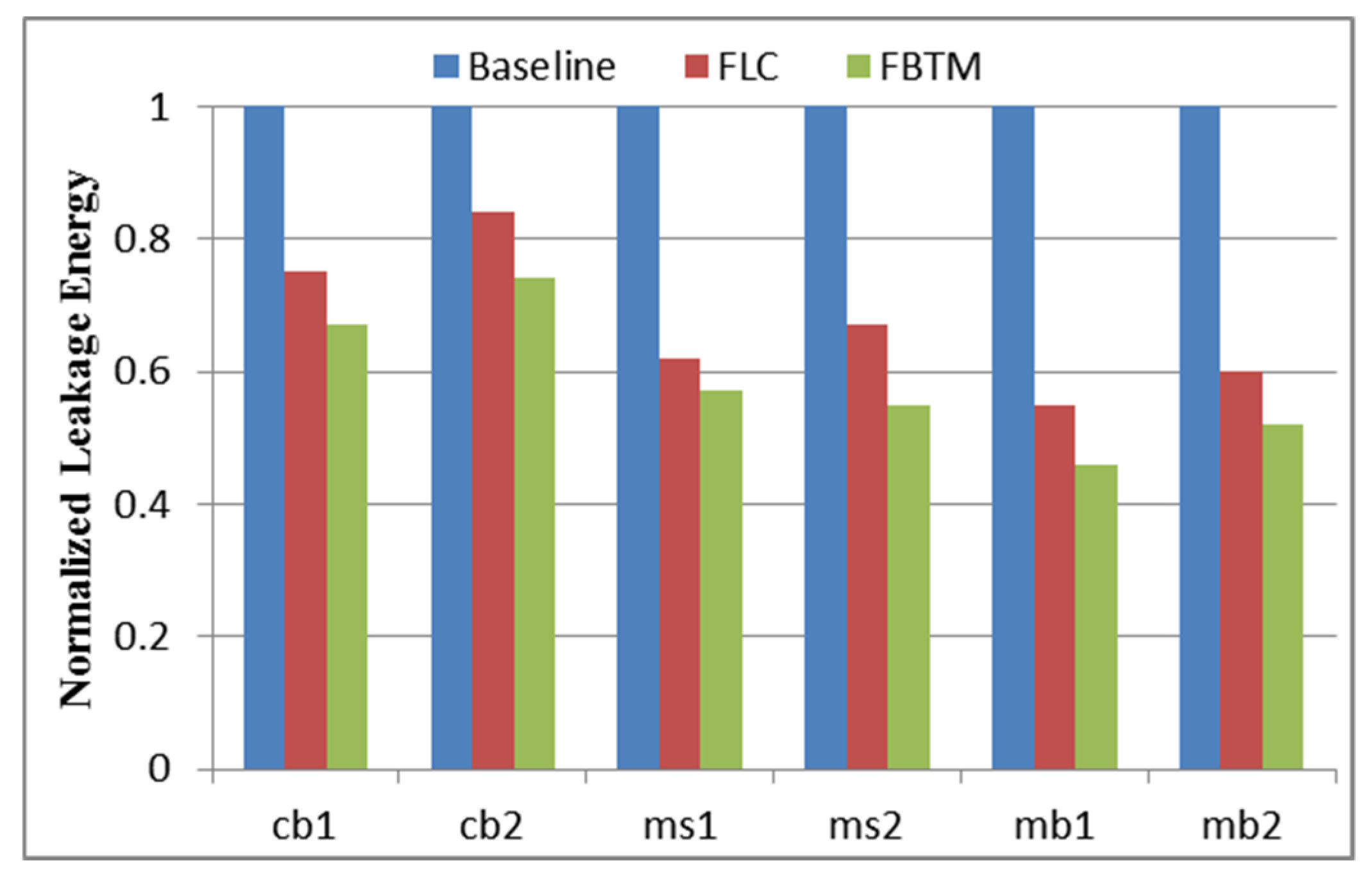
Leakage energy is the main component of the energy that can be saved by dynamically reconfiguring the cache size. Similarly, a reduction in temperature can also reduce the leakage energy of a system. The leakage energy reduction for the FLC and the FBTM normalized to the baseline is shown in Figure 7. On average, it was found that the FLC saved 33% in leakage energy, whereas the FBTM saved 41% for different test program suits. Shutting down the unused cache banks not only saves energy but also helps to control the temperature.
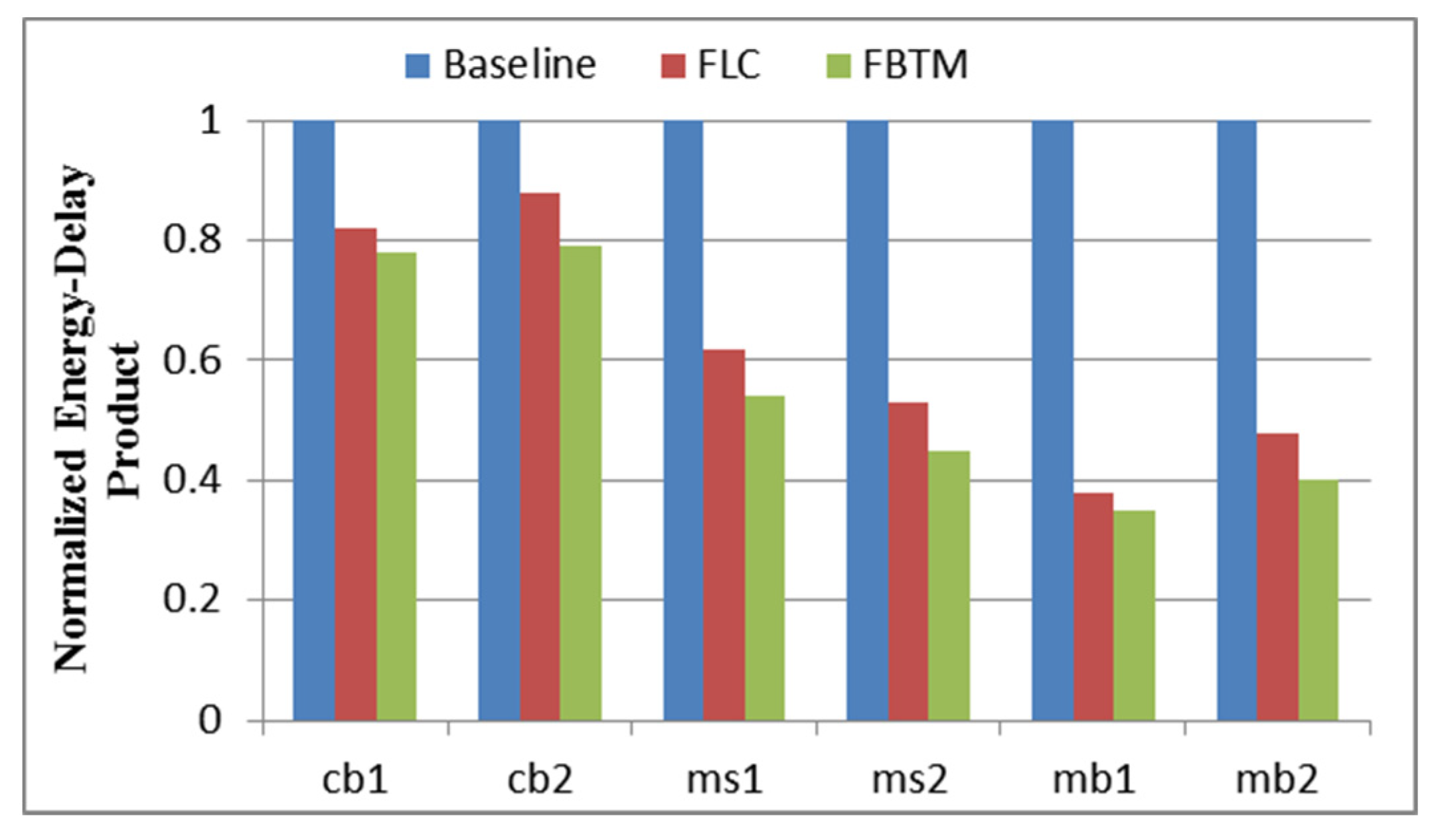
The results of energy efficiency normalized to the baseline for every program set are shown in Figure 8. Energy efficiency for thermal management schemes is called the energy-delay product (EDP). As shown in Figure 8, the FLC reached up to a 61% EDP reduction in comparison with the baseline, because the FLC regulated the frequency level of the processor core in real-time and finished the execution earlier than the baseline. Similarly, the FBTM reached up to a 65% EDP reduction compared with the baseline. The FBTM reached up to a 20% EDP reduction in comparison with the FLC because of the lower leakage power consumption. Compared with the baseline, the FLC and the FBTM reduced EDP by an average of 39% and 45%, respectively.
5. Conclusions
In this work, we proposed a fuzzy-based thermal management scheme (FBTM) for 3D chip multicores with stacked caches. Processor cores and stacked caches are the main components that affect the power consumption of systems. The proposed thermal management method considers both processor cores and caches, and it combines a dynamic cache reconfiguration scheme with fuzzy-based control policy in a temperature-aware manner. The dynamic cache reconfiguration scheme determines the size of the cache for the processing core according to the application that reaches a substantial amount of power consumption savings. The fuzzy-based control policy considers a feedback loop between the temperature and the power consumption to improve thermal control quality. The experimental results showed that the FBTM is able to achieve 3 degrees of reduction on average in temperature and is able to achieve a 41% reduction of leakage energy compared to an existing thermal management method.
Author Contributions
Conceive, methodology, and structure of this paper, L.S.; Resources, N.W.; Supervision, N.W.; Writing-original draft, L.S.; Validation, L.S. and G.Y.; Software, L.S.; Investigation, L.S. and G.Y.; Review and Editing, L.S. and Y.Z.; All authors have read and agreed to the published version of the manuscript.
Funding
This work was supported by the National Natural Science Foundation of China (No.61774086), the Natural Science Foundation of Jiangsu Province (No. BK20160806).
Acknowledgments
The authors would like to thank anonymous reviewers for their special effort.
Conflicts of Interest
The authors declare no conflict of interest.
References
- Burger, D.; Goodman, J.R.; Kagi, A. Limited bandwidth to affect processor design. IEEE Micro 1997, 17, 55–62. [Google Scholar] [CrossRef]
- Kim, C.; Burger, D.; Keckler, S.W. An adaptive, non-uniform cache structure for wire-delay dominated on-chip caches. ACM SIGARCH Comput. Archit. News 2002, 37, 211–222. [Google Scholar] [CrossRef] [Green Version]
- Kang, K.K.; Kim, J.; Yoo, S.; Kyung, C.M. Temperature-Aware Integrated DVFS and Power Gating for Executing Tasks with Runtime Distribution. IEEE Trans. Comput.-Aided Des. Integr. Circuits Syst. 2010, 29, 1381–1394. [Google Scholar] [CrossRef]
- Meng, J.; Kawakami, K.; Coskun, A.K. Optimizing energy efficiency of 3-D multicore systems with stacked DRAM under power and thermal constraints. In Proceedings of the DAC Design Automation Conference 2012, San Francisco, CA, USA, 3–7 June 2012; pp. 648–655. [Google Scholar]
- Zheng, J.; Wu, N.; Zhou, L.; Ye, Y.; Sun, K. DFSB-Based Thermal Management Scheme for 3-D NoC-Bus Architectures. IEEE Trans. Very Large Scale Integr. Syst. 2016, 24, 920–931. [Google Scholar] [CrossRef]
- Zhang, C.; Vahid, F.; Najjar, W.A. A Highly Configurable Cache for Low Energy Embedded Systems. ACM Trans. Embed. Comput. Syst. 2005, 4, 363–387. [Google Scholar] [CrossRef] [Green Version]
- Sun, G.; Wu, X.; Xie, Y. Exploration of 3D stacked L2 cache design for high performance and efficient thermal control. In Proceedings of the 2009 ACM/IEEE international symposium on Low power electronics and design, San Francisco, CA, USA, 19–21 August 2009; pp. 295–298. [Google Scholar]
- Wang, W.; Mishra, P. Leakage-aware energy minimization using dynamic voltage scaling and cache reconfiguration in real-time systems. Processing of the 2010 23rd International Conference on VLSI Design, Bangalore, India, 3–7 January 2010; pp. 357–362. [Google Scholar]
- Zhou, X.; Yang, J.; Xu, Y.; Zhang, Y.; Zhao, J. Thermal-aware task scheduling for 3D multicore processors. IEEE Trans. Parallel Distrib. Syst. 2010, 21, 60–71. [Google Scholar] [CrossRef]
- Puttaswamy, K.; Loh, G.H. Implementing caches in a 3d technology for high performance processors. In Proceeding of the 2005 International Conference on Computer Design, San Jose, CA, USA, 2–5 October 2005; pp. 525–532. [Google Scholar]
- Zhu, G.; Gu, Z.; Shang, L.; Dick, R.P.; Joseph, R. Three-dimensional chip-multiprocessor run-time thermal management. IEEE Trans. Comput.-Aided Des. Integr. Circuits Syst. 2008, 27, 1479–1492. [Google Scholar] [CrossRef] [Green Version]
- Wang, S.; Bettati, R. Reactive speed control in temperature-constrained real-time systems. Real-Time Syst. 2008, 39, 73–95. [Google Scholar] [CrossRef] [Green Version]
- Huang, W.; Ghosh, S.; Velusamy, S.; Sankaranarayanan, K.; Skadron, K.; Stan, M.R. HotSpot: A compact thermal modeling methodology for early-stage VLSI design. IEEE Trans. Very Large Scale Integr. (VLSI) Syst. 2006, 14, 501–513. [Google Scholar] [CrossRef]
- Balasubramonian, R.; Kahng, A.B.; Muralimanohar, N.; Shafiee, A.; Srinivas, V. CACTI 7: New Tools for Interconnect Exploration in Innovative Off-Chip Memories. ACM Trans. Archit. Code Optim. (TACO) 2017, 14, 1–25. [Google Scholar] [CrossRef]
- Standard Performance Evaluation Corporation. Available online: http://www.specbench.org (accessed on 3 May 2019).
- Binkert, N.; Beckmann, B.; Black, G.; Reinhardt, S.K.; Saidi, A.; Basu, A.; Hestness, J.; Hower, D. The gem5 simulator. ACM SIGARCH Comput. Archit. News 2011, 39, 1–7. [Google Scholar] [CrossRef]
- Li, S.; Ahn, J.H.; Strong, R.D.; Brockman, J.B.; Tullsen, D.M.; Jouppi, N.P. McPAT: An integrated power, area, and timing modeling framework for multicore and manycore architectures. In Proceedings of the 42nd Annual IEEE/ACM International Symposium on Microarchitecture, New York, NY, USA, 12–16 December 2009; pp. 469–480. [Google Scholar]
- Kang, K.; Jung, J.; Kyung, C.M. Performance maximization of 3D-stacked cache memory on DVFS-enabled processor. In Proceeding of the 2010 International SoC Design Conference, Seoul, Korea, 22–23 November 2010; pp. 47–50. [Google Scholar] [CrossRef]
- Wang, Y.; Ma, K.; Wang, X. Temperature-constrained power control for chip multiprocessors with online model estimation. In Proceedings of the 36th Annual International Symposium on Computer Architecture, Austin, TX, USA, 20–24 June 2009; pp. 314–324. [Google Scholar]
Figure 1.
Die floorplan of 3D-stacked non-uniform cache architecture (NUCA) cache architecture.

Figure 2.
Thermal model of a super-core i.

Figure 3.
Proposed thermal management scheme.

Figure 4.
Closed-loop system.

Figure 5.
Membership function of the linguistic variables. (a) e, (b) , and (c) F.

Figure 6.
Comparison of the transient maximum temperature. (a) Executing the mem2 program set. (b) Executing com2 program set.
Figure 6.
Comparison of the transient maximum temperature. (a) Executing the mem2 program set. (b) Executing com2 program set.

Figure 7.
Comparison of leakage energy results.

Figure 8.
Comparison of energy-delay product (EDP) results.


Table 1.
Algorithm 1.
| Algorithm 1: |
|---|
|
Table 2.
Fuzzy control rules
| Input | Output | |
|---|---|---|
| F | ||
| Low | Negative | High |
| Low | Zero | High |
| Low | Positive | Medium |
| Normal | Negative | High |
| Normal | Zero | Medium |
| Normal | Positive | Low |
| High | Negative | Medium |
| High | Zero | Low |
| High | Positive | Low |
Table 3.
Multiprogrammed workloads used in the experiment.
| Test Program Set | Benchmarks |
|---|---|
| Compute-intensive set (com1) | equake, parser, bzip, applu |
| Compute-intensive set (com2) | hmmer, mpeg_dec, astar |
| Medium set (med1) | mcf, bzip, gcc, sphinx3 |
| Medium set (med2) | leslie3d,mlic, omnetpp, calculix |
| Memory-intensive set (mem1) | lbm, art, swim, zeusmp |
| Memory-intensive set (mem2) | libquantum, lbm, GemsFDTD, art |
© 2020 by the authors. Licensee MDPI, Basel, Switzerland. This article is an open access article distributed under the terms and conditions of the Creative Commons Attribution (CC BY) license (http://creativecommons.org/licenses/by/4.0/).
Share and Cite
MDPI and ACS Style
Shen, L.; Wu, N.; Yan, G. Fuzzy-Based Thermal Management Scheme for 3D Chip Multicores with Stacked Caches. Electronics 2020, 9, 346. https://0-doi-org.brum.beds.ac.uk/10.3390/electronics9020346
AMA Style
Shen L, Wu N, Yan G. Fuzzy-Based Thermal Management Scheme for 3D Chip Multicores with Stacked Caches. Electronics. 2020; 9(2):346. https://0-doi-org.brum.beds.ac.uk/10.3390/electronics9020346
Chicago/Turabian StyleShen, Lili, Ning Wu, and Gaizhen Yan. 2020. "Fuzzy-Based Thermal Management Scheme for 3D Chip Multicores with Stacked Caches" Electronics 9, no. 2: 346. https://0-doi-org.brum.beds.ac.uk/10.3390/electronics9020346
Note that from the first issue of 2016, this journal uses article numbers instead of page numbers. See further details here.