Effect of A Superstrate on On-Head Matched Antennas for Biomedical Applications


1
Department of Electronic and Telecommunications Engineering, School of Engineering, RMIT University, Melbourne 3001, Australia
2
Department of Electronic Engineering and Computer Science, School of Electronic Engineering and Computer Science, Queen Mary University of London, London E1 4NS, UK
*
Author to whom correspondence should be addressed.
Electronics 2020, 9(7), 1099; https://0-doi-org.brum.beds.ac.uk/10.3390/electronics9071099
Submission received: 2 June 2020
/
Revised: 29 June 2020
/
Accepted: 2 July 2020
/
Published: 6 July 2020
(This article belongs to the Special Issue Microwave Devices Design and Application)
Abstract
:The effect of using a superstrate dielectric layer on an on-head matched antenna for biomedical diagnosis applications is investigated. Two on-head matched antennas are considered with different length meandered lines ensuring operation around 0.9 GHz frequency. The first antenna’s conductive radiating structure is in direct contact with the head phantom, whereas the second one utilises a 0.5 mm thick superstrate layer on top of the conducting layer as a buffer. The lateral dimensions of both antennas are held constant at 30 × 30 mm2. The electric and magnetic field distribution is analysed and the power penetration, 50 mm inside the head phantom, is derived from the electromagnetic field surrounding the antennas. Both homogeneous and inhomogeneous head phantoms are considered while evaluating the antennas in terms of their reflection coefficient, current distribution, electric field, magnetic field, specific absorption rate (SAR) and power penetration inside the head. The antennas are fabricated and measured utilizing an inhomogeneous phantom to validate the proposed performance improvement using a superstrate. It is shown that the superstrate antenna achieves a ~8 dB increase in power penetration inside the head phantom along with a 0.0731 W/kg decrease in SAR compared to the antenna without a superstrate.
1. Introduction
The microwave regime has gained its popularity over the last decade for medical diagnosis applications due to its non-ionizing radiation, low-cost, and time efficient advantages. The microwave antenna can act as the radiating element for stroke diagnosis, chemo-thermotherapy, and head imaging [1,2,3,4]. Numerous antennas have been proposed to achieve signal propagation inside human tissue without touching the surface of the human body. A coplanar waveguide (CPW)-fed antenna designed for medical diagnosis is reported in [5], where the antenna is designed to be operating at the far field from the human body. Another antenna for brain stroke detection is reported in [6], providing both the far field and near field characteristics of the antenna. However, the antenna also operates without touching the human body. A similar approach is taken when designing antennas for medical diagnosis in [3,7,8].
Antennas that contact with the surface of human tissue are more likely to provide increased penetration compared to those operating in air due to reflections at the air-skin interface. Relatively few antenna designs are reported in the literature which are directly attached to the human body for operation. In [9], a bowtie shaped antenna matched to a human head model is reported. The top antenna conductor directly touches the human head surface to achieve impedance matching. The radiation pattern of the antenna is characterized at the boresight direction only. Antenna designs with a similar operation principle are reported in [10,11] for breast cancer detection application where the antenna conductor plane is in direct connection with the skin layer of the breast. It is reported in [12,13,14] that a direct connection between the antenna and human tissue results in a poor antenna performance. However, there is no evidence of a direct comparison between antennas with and without direct contact of the conductor of the antenna with human tissue.
In some cases, direct contact between the antenna conductor layer and the human tissue is prevented by using a superstrate. A wideband antenna design is reported to detect early congestive heart failure employing a foam material as a superstrate and around the antenna to achieve durability during operation [15]. However, the foam material that is used outside of the antenna shielding the conductors from directly touching human tissue is not considered in the simulation. For thrombolytic treatment with microwave operated medical diagnosis systems, a patch antenna covered by a plastic container holding a matching liquid is utilized [1]. However, the impact of the container filled with water on the performance of the antenna was not investigated. An antenna utilizing a superstrate layer in the boresight direction of the antenna is reported in [16], but the performance of the antenna without a superstrate is omitted in the simulation and measurement and hence its effect cannot be determined. A superstrate layer is widely used for implantable antenna designs as well where the conductor contact with the human tissue is unwanted. An implantable antenna to monitor intracranial pressure of human head is presented in [17], equipped with a battery and data and power management circuitry encapsulated in a container. The container made of Alumina (Al2O3) isolates the whole antenna system from the human tissue. In [18], an implantable antenna operating at 2.4 GHz is reported for biomedical applications which uses a superstrate layer of Rogers 6010 material to achieve separation of the human tissue from the antenna conducting layer. Similar mechanisms to achieve antenna isolation from the human tissue are reported in [19,20,21]. In all these proposed implantable antennas, a comparative characterization of the presence of a superstrate layer is omitted so the usefulness and impact of the superstrate cannot be determined.
In this study we investigate the effectiveness of a superstrate layer on the performance of an on-head matched antenna, particularly with regards to power penetration pattern and SAR. As identified above there is a need for systematic characterization and comparison of the impact of a superstrate for antennas mounted in direct contact with the human body. Two on-head matched antennas, one with a superstrate and one without, are designed to compare the antenna performance. Both antennas are impedance matched at a similar frequency range to achieve a more rational comparison. The overall lateral dimensions of the antennas are fixed at 30 × 30 mm2 while achieving −10 dB impedance matching at around 0.9 GHz. An inhomogeneous head model is empolyed in the analysis and comparison of the antennas, and the importance of considering the inhomogeneity is highlighted. A realistic human head phantom with skin, bone and brain mimicking materials is constructed for verification of the results. The reflection coefficient, E- and H-fields, power penetration pattern, and specific absorption rate (SAR) inside a human head phantom are evaluated, considering both homogeneous and inhomogeneous lossy tissue models to establish the effect of a superstrate in antenna designs for biomedical applications.
2. Antenna Designs and Numerical Settings
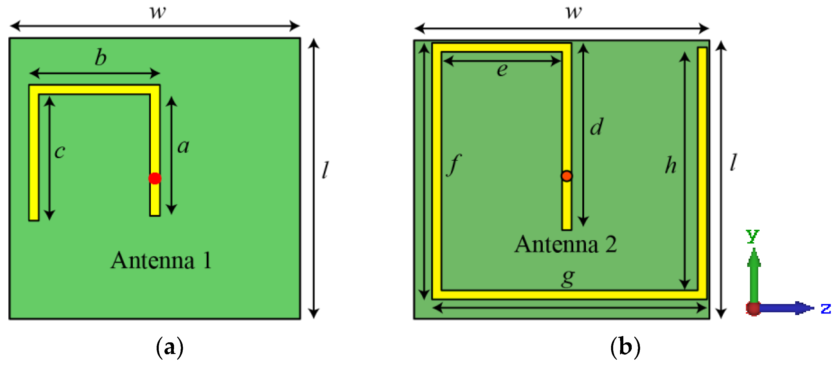
The antennas depicted in Figure 1 utilize FR4 dielectric material with a thickness of 1.6 mm. Antenna 1 in Figure 1a is designed to operate in contact with a human head without a superstrate layer. The thickness of the superstrate for Antenna 2 shown in Figure 1b is 0.5 mm, and is also made of FR4. With the aid of the high permittivity of human head, the radiating conductor of Antenna 2 achieves a short meandered length of a + b + c (0.12λ0) while achieving a good impedance matching at around 0.9 GHz. This frequency was targeted as the lower microwave frequency region is reported to be more suitable compared to higher microwave frequencies to achieve increased signal propagation inside human tissue [22]. The aim for Antenna 2 was to keep identical overall footprint of 30 × 30 mm2 of Antenna 1 for effective comparison. As the Antenna 2 lacks the advantage of being in direct contact with high permittivity human head phantom, the length of the conductive meander line is extended to d + e + f + g + h to achieve impedance matching at 0.9 GHz. The feed position also remains constant for both antennas in the middle of the ground plane on the reverse side.
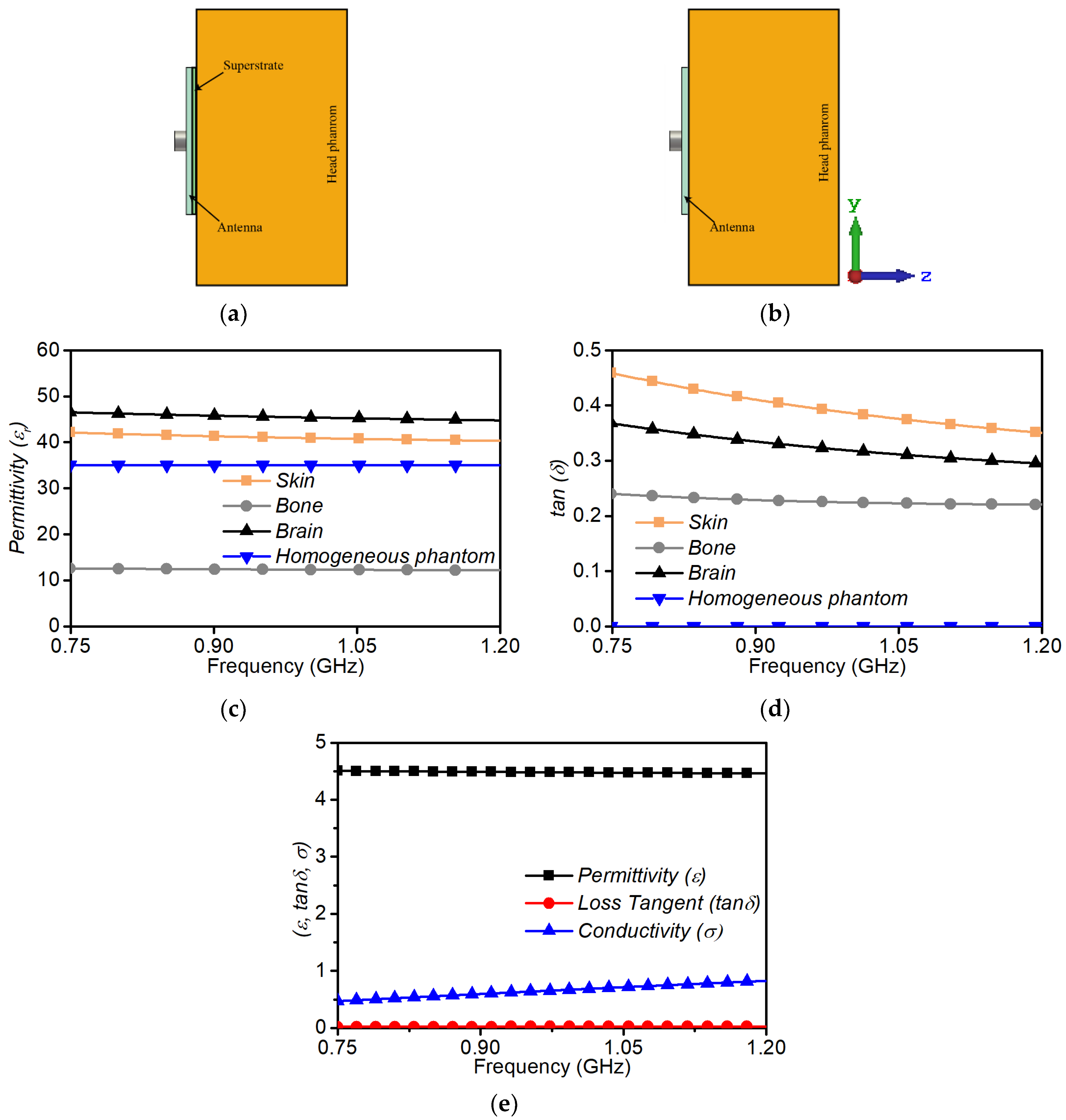
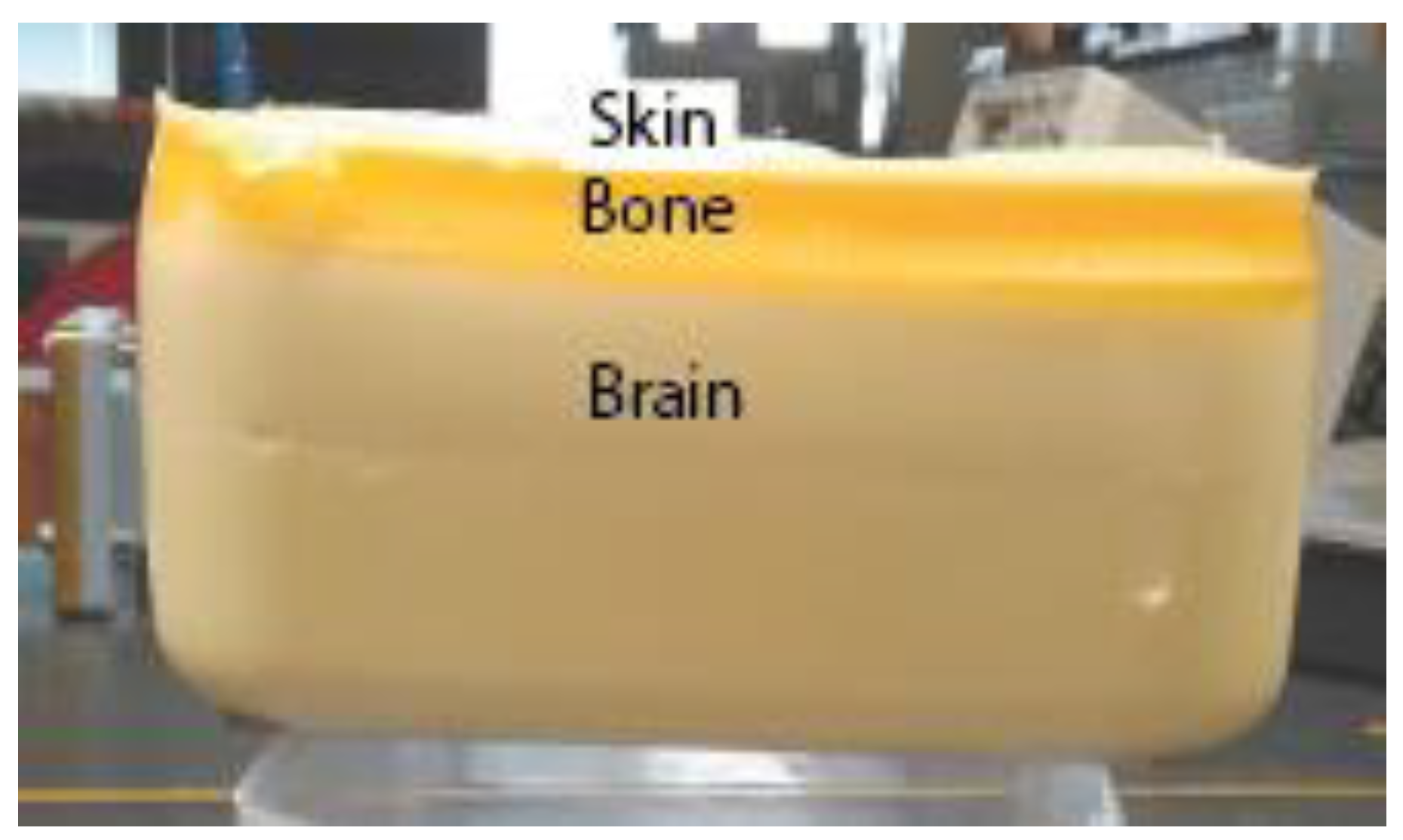
The simulation setups depicted in Figure 2 consider the antennas affixed to the surface of a human head phantom, and were executed in computer simulation technology (CST) 2017 [23]. For Antenna 1, the antenna conductor plane is in direct contact with the head phantom as shown in Figure 2a, whereas Antenna 2 is buffered by the superstrate (Figure 2b). The antennas were evaluated against both homogeneous and inhomogeneous human head phantoms. The homogeneous phantom is constructed with permittivity εphantom = 35 and conductivity σphantom = 0.5 S/m [9] with dimensions 80 × 80 × 60 mm3. The inhomogeneous head phantom is constructed using layered skin, bone and brain tissue materials from the CST 2017 library. The thickness used for the skin, bone and brain layers are 3 mm, 10 mm and 50 mm respectively. Figure 2c,d depicts the permittivity and loss tangent respectively of the utilized tissue materials to construct the phantom in terms of frequency, and Figure 2e presents the dielectric properties of the superstrate.
The surface current density of the antenna can be calculated utilizing Ampere’s Law among the Maxwell’s equations for time varying fields:
Here, = magnetic field, µ0 = permeability, = current density, ε0 = permittivity, and = electric field. The current distribution patterns of the two antennas at 0.9 GHz are shown in Figure 3. In Figure 3a the current flow intensity for Antenna 1 peaks near the feed point and decays towards the first 90° bend in the conducting line and is almost completely extinguished half way down the length of the line. Such a distribution occurs due to the direct connection between the antenna conducting plane and the conductive human head models. In Figure 3b, the current distribution for Antenna 2 shows distributed current flow across almost the entire length of the conductive meander line of the antenna, indicating its length is mostly responsible for impedance matching at 0.9 GHz. The superstrate inhibits the current from directly flowing towards the conductive human head phantom. The surface current distributions of Antennas 1 and 2 remain largely similar for both homogeneous and inhomogeneous head models.
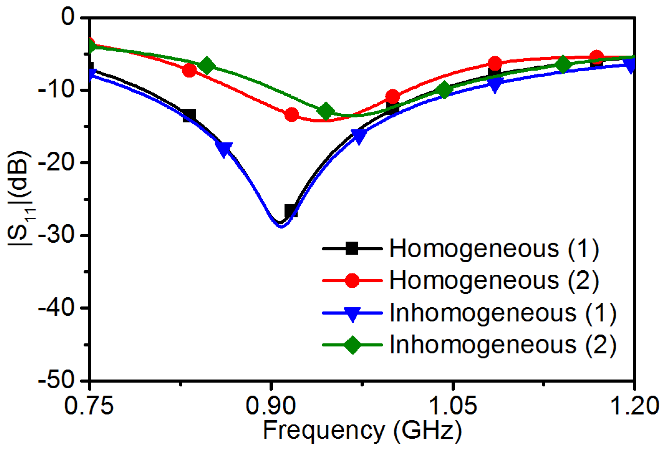
The |S11| responses of the antennas are shown in Figure 4. Antenna 1 with homogeneous head phantom possesses an impedance bandwidth of 0.25 GHz with the |S11| response below −25 dB at 0.9 GHz. The impedance dip of Antenna 2 occurs at 0.95 GHz, a 0.05 GHz offset from Antenna 1, with an impedance bandwidth of 0.14 GHz for the homogeneous head phantom. Nonetheless, the |S11| response for Antenna 2 at 0.9 GHz is below −10 dB providing minimal reflection at the desired frequency. The discrepancy between the two antennas is due to the set requirement of maintaining a 30 × 30 mm2 footprint for Antenna 2. To maintain a simple meandered loop shape, the length of the line is limited and can only reduce the centre of the impedance bandwidth down to 0.93 GHz. Similar |S11| responses can be found with the inhomogeneous head phantom, with corresponding overall meander length issues for Antenna 2.
3. Numerical and Experimental Results and Analyses
3.1. Numerical Simulations
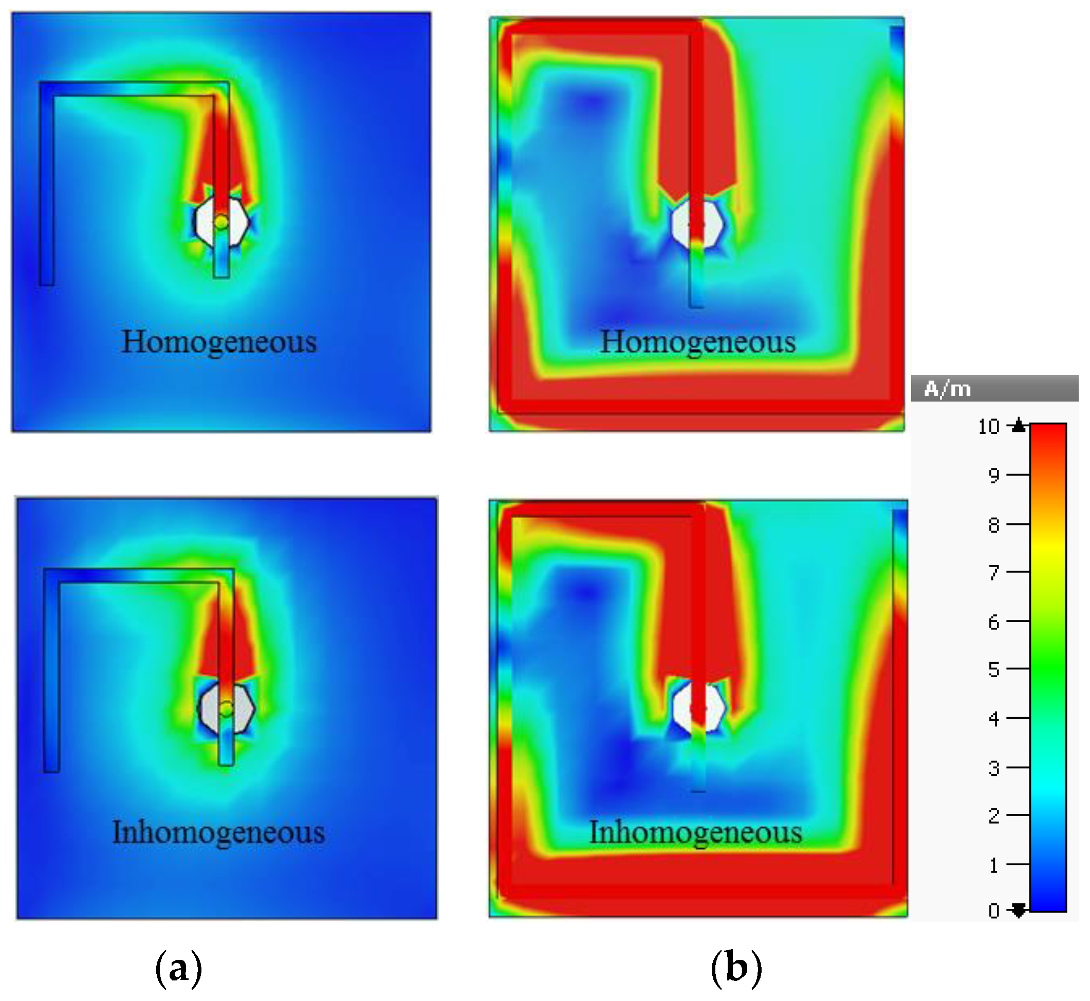
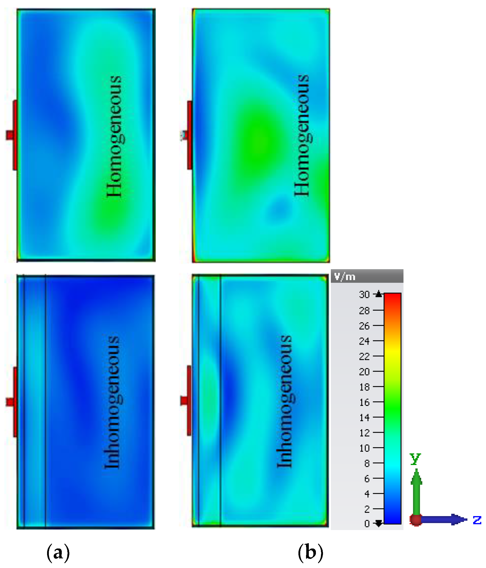
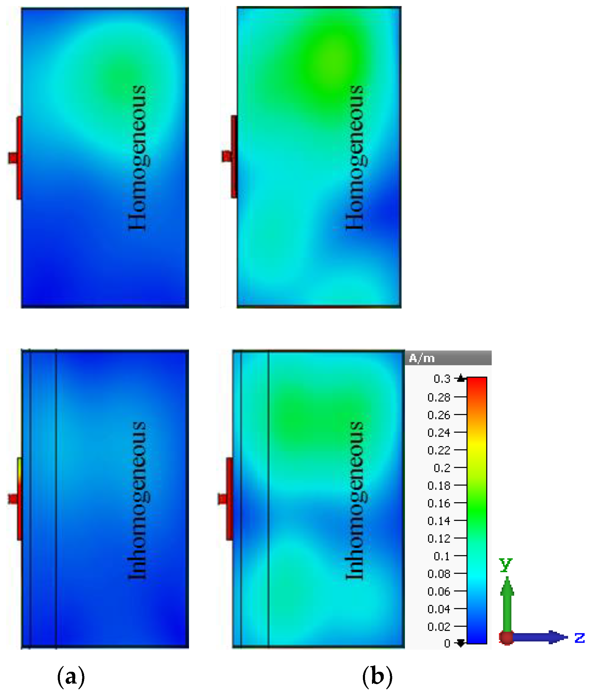
The E-field and H-field distributions inside the human head phantom with the two antennas attached are depicted in Figure 5 and Figure 6 respectively. Stronger, more evenly distributed fields are seen inside the homogeneous human head phantom for Antenna 2 (in Figure 5b and Figure 6b) than Antenna 1 (in Figure 5a and Figure 6a). The superstrate layer in Antenna 2 shields the conductor from leaking energy directly into the lossy material, allowing significantly more to penetrate into the head.
Once the more realistic inhomogeneous head phantom is considered, Antenna 2 generates significantly more E- and H-field intensity than Antenna 1. Only a very small portion of the field penetrates the skin and bone layers into the brain for Antenna 1 mounted on the inhomogeneous phantom. This is because the propagation modelling must consider the successive reflections at the boundaries between the tissues, which can be significant due to the large variation in layer permittivity properties. This highlights the importance of utilizing an inhomogeneous model in the design of biomedical antennas.
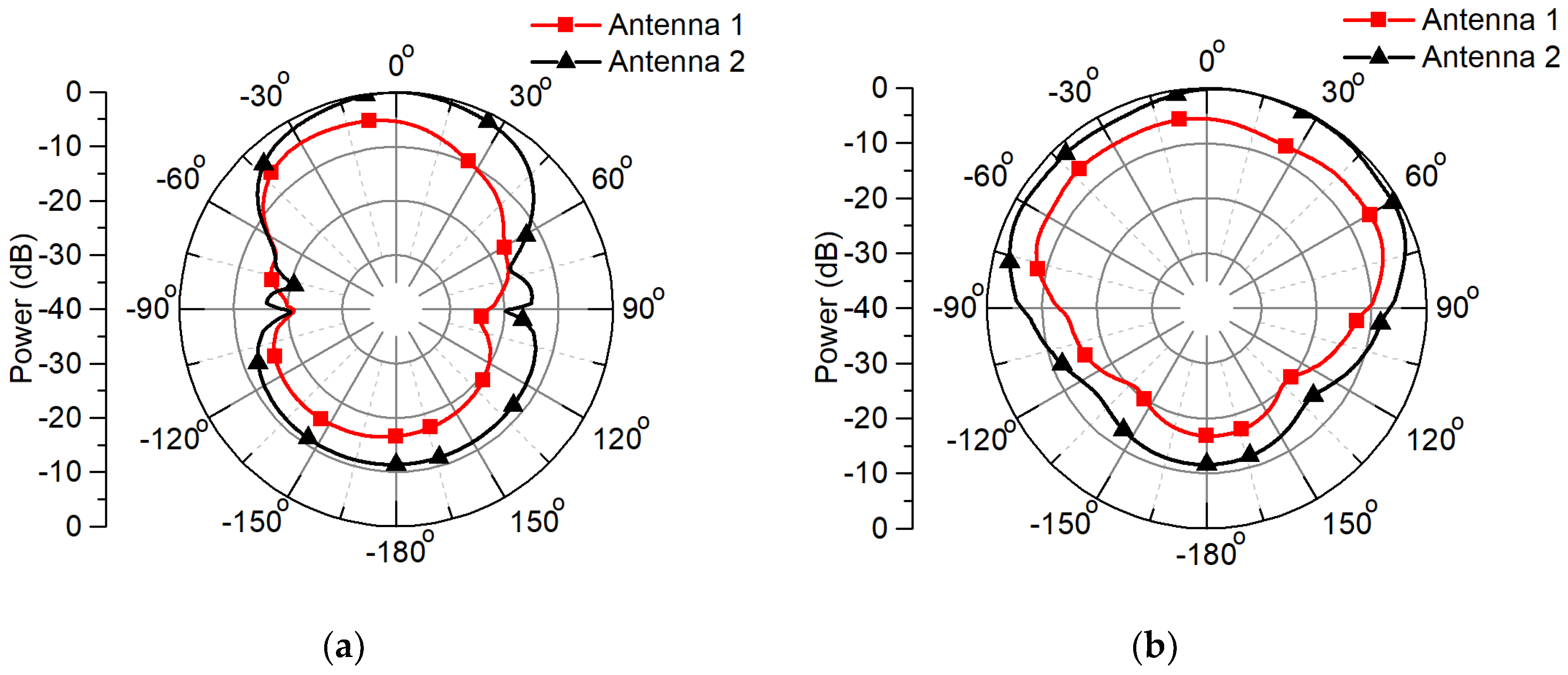
Figure 7 illustrates the xz- and yz-plane normalized near field power radiation pattern of the antennas along a 50 mm radius from the antenna feed centre for the homogeneous phantom, where 0° represents the +z direction. Although the patterns are of similar shape, the power radiation level is approximately 6 dB lower for Antenna 1 compared to Antenna 2 towards the boresight direction (0°) into the homogeneous head phantom. This corroborates with the field results of Figure 5 and Figure 6. The front to back ratio (FBR) of the power radiation patterns for Antenna 1 and Antenna 2 are 11.18 dB and 11.4 dB respectively.
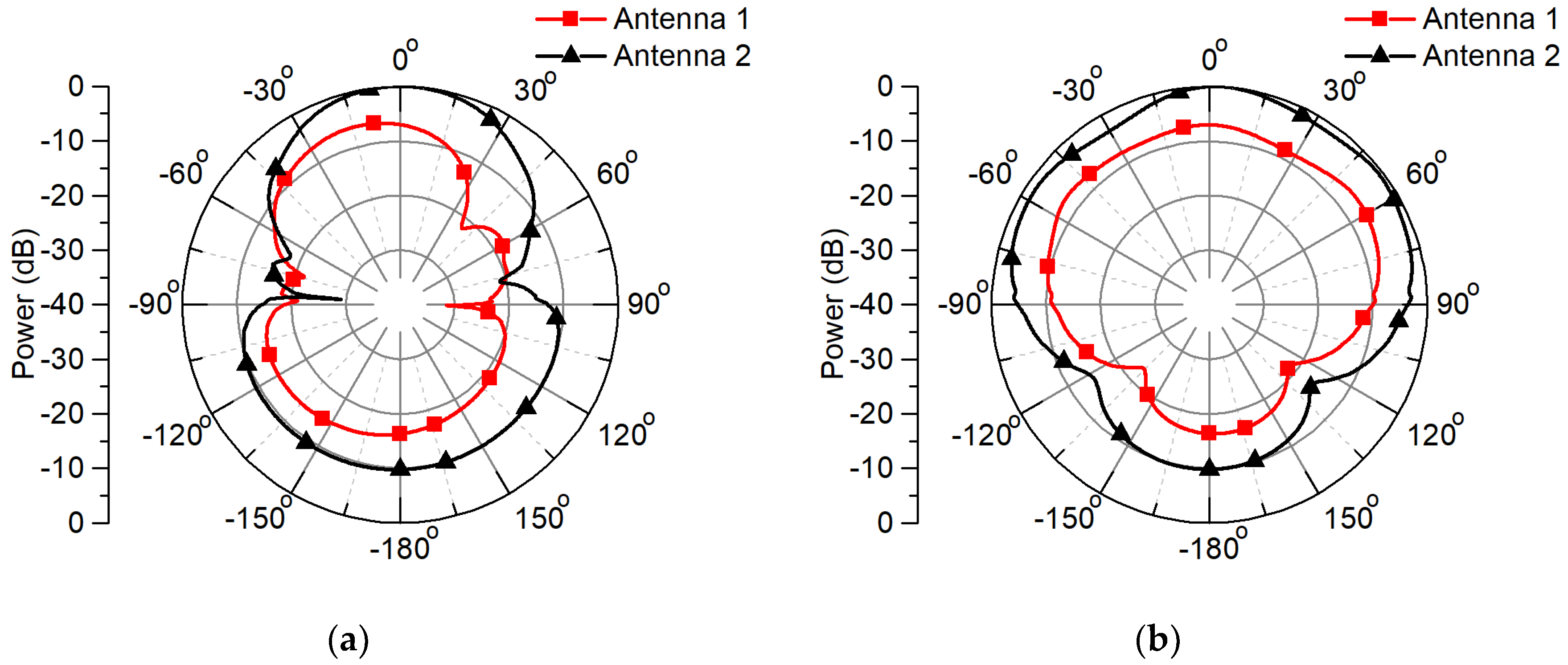
The normalized near field power radiation patterns when the inhomogeneous head phantom is utilized are depicted in Figure 8 for Antenna 1 and Antenna 2 at 0.9 GHz. The power penetration inside the inhomogeneous head phantom is 7 dB more for Antenna 2 as compared to Antenna 1 at the boresight direction of the antennas, and the FBR for Antenna 1 and Antenna 2 are 9.32 dB and 9.78 dB respectively. Variations in the main lobes of the antenna patterns are evident when the inhomogeneous head phantom is used, which are not there in the homogeneous case. These variations can be attributed to interference patterns generated by field reflections occurring at the interfaces between tissue layers.
As the human head comprises of inhomogeneous tissue characteristics, a simple homogeneous model is not adequate. The results of Figure 5, Figure 6, Figure 7 and Figure 8 indicate that to achieve more representative antenna design for biomedical applications such as on-head matched case, the inhomogeneity of human head needs to be considered.
SAR is an important parameter for biomedical applications, especially when an antenna is operating near or on a human body. The SAR is defined by the time derivative of the incremental energy (dW) absorbed by an incremental mass (dm):
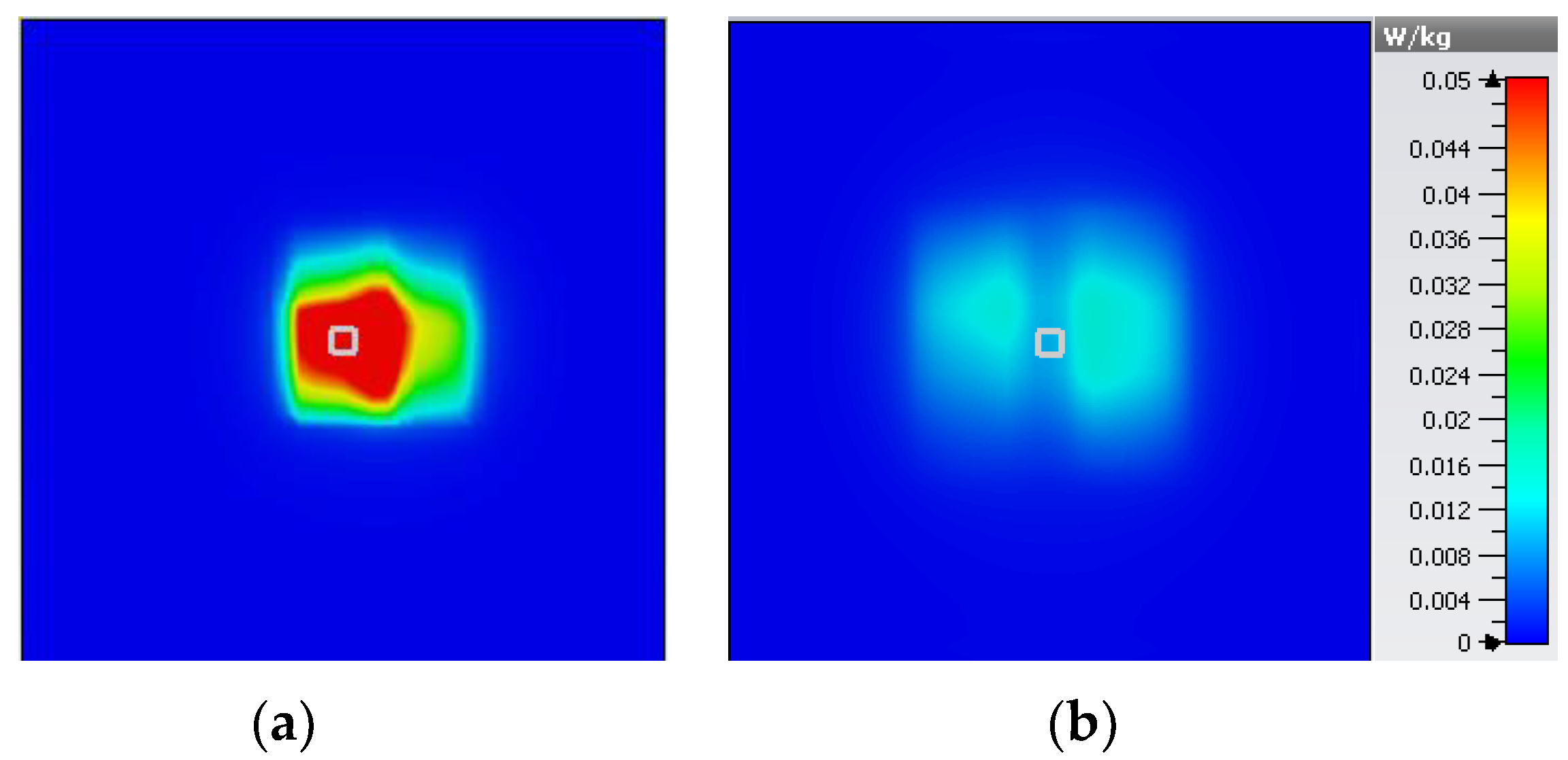
Using the built-in calculation system for human tissues in CST 2017 the SAR can be evaluated, indicating the absorption of energy by the tissue. As CST 2017 can only evaluate SAR for human tissue materials, the SAR response for the homogeneous head phantom (a bulk dielectric) cannot be calculated. Figure 9 displays the computed SAR for Antenna 1 and Antenna 2 at 0.9 GHz at the surface of the skin layer of the inhomogeneous phantom. The maximum 10 g average SAR for Antenna 1 and Antenna 2 are 0.0884 W/kg and 0.0153 W/kg when an input power of 1 mW is applied to each antenna. Although the SAR for Antenna 1 is over 5 time more than Antenna 2, both of the SAR levels are well below the general human exposure limit of SAR [24].
3.2. Experimental Validation
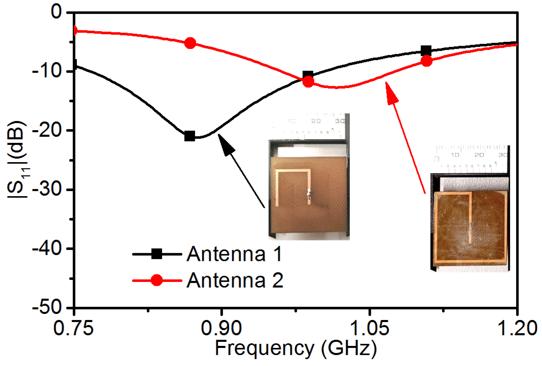
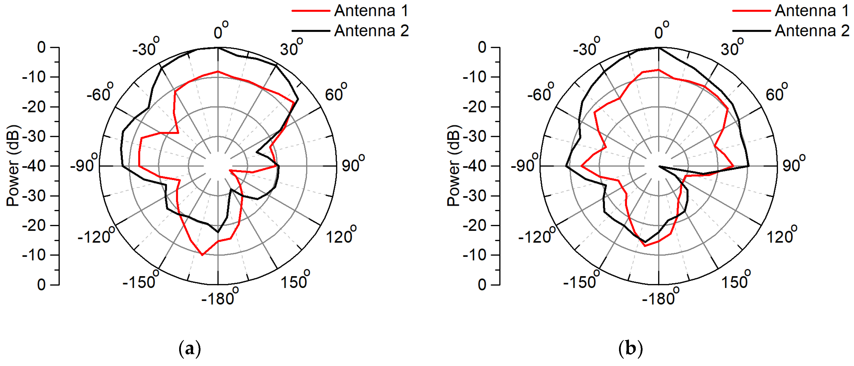
The antennas are fabricated on FR4 substrates using the UV precision processing system (DL561U) from design comes true (DCT). Antenna 1 is without a superstrate, and the superstrate of Antenna 2 is attached on top using an epoxy glue which has similar permittivity (~3.5) to the FR4 material. The antennas are fed through the ground plane using an subminiature-A (SMA) connector. Figure 10 depicts the measured |S11| response of the two antennas when they are attached to the fabricated inhomogeneous human head phantom shown in Figure 11. The details of the measurement setup and the head phantom can be found in [16]. Both the antennas exhibit similar characteristics to those predicted in the simulation for the inhomogeneous human head phantom in Figure 4. The normalized near field power radiation pattern is shown in Figure 12, with measurement points taken every 10º at a 50 mm radius for both xz- and yz-plane of the antennas. As the power radiation pattern are normalized to the peak value from both patterns, it can be observed that Antenna 2 directs ~8 dB more power towards boresight than Antenna 1. The FBR for Antenna 1 is 6.5 dB whereas for Antenna 2 it is 17.7 dB, again indicating more substantial levels of power directed into the head phantom. Table 1 compares the properties of the proposed antennas to relative antennas for biomedical applications. Antenna 2’s use of a superstrate enables it to be comparable or outperform the leading antennas in the literature, particularly in terms of SAR and FBR.
4. Conclusions
In this paper, two antennas for on-head biomedical applications are designed with identical lateral dimension of 30 × 30 mm2, both operating at 0.9 GHz. The antennas differ in relation to the presence (or not) of a superstrate layer between the antenna and a human head phantom. An analysis as to the effect of the superstrate layer is undertaken in terms of current distribution, E- and H-field penetration, near field power radiation pattern and SAR when utilizing both a homogeneous and inhomogeneous layered human head phantom. The antenna without the superstrate is less effective at achieving field/power penetration deep inside the phantom, primarily due to the direct contact of the antenna conductors with the lossy high permittivity tissues. The antenna with the superstrate achieves more significant field/power penetration with a lower SAR on the skin surface due to the separation between the phantom and the antenna elements. The superstrate antenna achieves ~8 dB higher power penetration inside the head model in conjunction with a 0.0731 W/kg decrease in SAR compared to the antenna without a superstrate. Experimental validation of the antenna performance utilizing an inhomogeneous phantom was also achieved. The superstrate antenna also surpasses the performance of comparative biomedical antennas presented in the literature particularly in terms of SAR and FBR highlighting the importance and originality of this research. Hence this paper has provided evidence that including a superstrate in the structure of an on-head matched antenna for biomedical applications can provide increased power penetration inside human head with lower SAR.
Author Contributions
Conceptualization, M.R.R. and W.S.T.R.; methodology, M.R.R.; software, M.R.R.; validation, M.R.R., A.A. (Asif Ahmed) and A.A. (Akram Alomainy); formal analysis, M.R.R.; investigation, M.R.R. and A.A. (Asif Ahmed); resources, W.S.T.R.; data curation, M.R.R., A.A. (Akram Alomainy) and A.A. (Asif Ahmed); writing—original draft preparation, M.R.R.; writing—review and editing, M.R.R., W.S.T.R. and A.A. (Akram Alomainy); visualization, M.R.R. and A.A. (Asif Ahmed); supervision, W.S.T.R.; project administration, W.S.T.R.; funding acquisition, W.S.T.R. All authors have read and agreed to the published version of the manuscript.
Funding
This research received no external funding.
Conflicts of Interest
The authors declare no conflict of interest.
References
- Persson, M.; Fhager, A.; Trefná, H.D.; Yu, Y.; McKelvey, T.; Pegenius, G.; Karlsson, J.A.; Elam, M. Microwave-Based stroke diagnosis making global prehospital thrombolytic treatment possible. IEEE Trans. Biomed. Eng. 2014, 61, 2806–2817. [Google Scholar] [CrossRef] [Green Version]
- Asili, M.; Chen, P.; Hood, A.Z.; Purser, A.; Hulsey, R.; Johnson, L.; Ganesan, A.V.; Demirci, U.; Topsakal, E. Flexible microwave antenna applicator for chemo-thermotherapy of the breast. IEEE Antennas Wirel. Propag. Lett. 2015, 14, 1778–1781. [Google Scholar] [CrossRef]
- Rokunuzzaman, M.; Samsuzzaman, M.; Islam, M.T. Unidirectional Wideband 3-D antenna for human head-imaging application. IEEE Antennas Wirel. Propag. Lett. 2017, 16, 169–172. [Google Scholar] [CrossRef]
- Mobashsher, A.; Abbosh, A. Compact 3-D slot-loaded folded dipole antenna with unidirectional radiation and low impulse distortion for head imaging applications. IEEE Trans. Antennas Propag. 2016, 64, 3245–3250. [Google Scholar] [CrossRef]
- Mobashsher, A.; Abbosh, A. CPW-fed low-profile directional antenna operating in low microwave band for wideband medical diagnostic systems. Electron. Lett. 2014, 50, 246–248. [Google Scholar] [CrossRef]
- Mobashsher, A.T.; Abbosh, A. Development of compact directional antenna utilising plane of symmetry for wideband brain stroke detection systems. Electron. Lett. 2014, 50, 850–851. [Google Scholar] [CrossRef]
- Schwarz, U.; Thiel, F.; Seifert, F.; Stephan, R.; Hein, M. Ultrawideband antennas for magnetic resonance imaging navigator techniques. IEEE Trans. Antennas Propag. 2010, 58, 2107–2112. [Google Scholar] [CrossRef]
- Xu, L.J.; Duan, Z.; Tang, Y.M.; Zhang, M. A Dual-Band On-Body repeater antenna for body sensor network. IEEE Antennas Wirel. Propag. Lett. 2016, 15, 1649–1652. [Google Scholar] [CrossRef]
- Li, X.; Jalilvand, M.; Sit, Y.L.; Zwick, T. A compact double-layer on-body matched bowtie antenna for medical diagnosis. IEEE Trans. Antennas Propag. 2014, 62, 1808–1816. [Google Scholar] [CrossRef]
- Porter, E.; Bahrami, H.; Santorelli, A.; Gosselin, B.; Rusch, L.A.; Popović, M. A Wearable microwave antenna array for time-domain breast tumor screening. IEEE Trans. Med. Imaging 2016, 35, 1501–1509. [Google Scholar] [CrossRef] [Green Version]
- Bahramiabarghouei, H.; Porter, E.; Santorelli, A.; Gosselin, B.; Popovic, M.; Rusch, L.A. Flexible 16 Antenna Array for Microwave Breast Cancer Detection. Biomed. Eng. IEEE Trans. 2015, 62, 2516–2525. [Google Scholar] [CrossRef]
- Bocan, K.N.; Mickle, M.H.; Sejdić, E. Simulating, modeling, and sensing variable tissues for wireless implantable medical devices. IEEE Trans. Microw. Theory Tech. 2018, 66, 3547–3556. [Google Scholar] [CrossRef]
- Liu, Y.; Chen, Y.; Lin, H.; Juwono, F.H. A novel differentially fed compact dual-band implantable antenna for biotelemetry applications. IEEE Antennas Wirel. Propag. Lett. 2016, 15, 1791–1794. [Google Scholar] [CrossRef]
- Bakogianni, S.; Koulouridis, S. An implantable planar dipole antenna for wireless MedRadio-Band biotelemetry devices. IEEE Antennas Wirel. Propag. Lett. 2016, 15, 234–237. [Google Scholar] [CrossRef]
- Rezaeieh, S.A.; Zamani, A.; Bialkowski, K.; Abbosh, A. Foam embedded wideband antenna array for early congestive heart failure detection with tests using artificial phantom with animal organs. IEEE Trans. Antennas Propag. 2015, 63, 5138–5143. [Google Scholar] [CrossRef]
- Rokunuzzaman, M.; Ahmed, A.; Baum, T.C.; Rowe, W.S.T. Compact 3-D Antenna for medical diagnosis of the human head. IEEE Trans. Antennas Propag. 2019, 67, 5093–5103. [Google Scholar] [CrossRef]
- Shah, S.A.A.; Yoo, H. Scalp-Implantable antenna systems for intracranial pressure monitoring. IEEE Trans. Antennas Propag. 2018, 66, 2170–2173. [Google Scholar] [CrossRef]
- Yang, Z.J.; Xiao, S.Q.; Zhu, L.; Wang, B.Z.; Tu, H.L. A Circularly polarized implantable antenna for 2.4-GHz ISM band biomedical applications. IEEE Antennas Wirel. Propag. Lett. 2017, 16, 2554–2557. [Google Scholar] [CrossRef]
- Ma, S.; Sydänheimo, L.; Ukkonen, L.; Björninen, T. Split-Ring resonator antenna system with cortical implant and head-worn parts for effective far-field implant communications. IEEE Antennas Wirel. Propag. Lett. 2018, 17, 710–713. [Google Scholar] [CrossRef]
- Xu, L.J.; Guo, Y.X.; Wu, W. Miniaturized circularly polarized loop antenna for biomedical applications. IEEE Trans. Antennas Propag. 2015, 63, 922–930. [Google Scholar] [CrossRef]
- Liu, C.; Zhang, Y.; Liu, X. Circularly polarized implantable antenna for 915 MHz ISM-band far-field wireless power transmission. IEEE Antennas Wirel. Propag. Lett. 2018, 17, 373–376. [Google Scholar] [CrossRef]
- Poon, A.S.; O’Driscoll, S.; Meng, T.H. Optimal frequency for wireless power transmission into dispersive tissue. IEEE Trans. Antennas Propag. 2010, 58, 1739–1750. [Google Scholar] [CrossRef] [Green Version]
- Studio, C.M. 3D EM Simulation Software. Comput. Simul. Technol. 2017. Available online: https://www.remcom.com/xfdtd-3d-em-simulation-software (accessed on 2 June 2020).
- IEEE Standard for Safety Levels with Respect to Human Exposure to Radio Frequency Electromagnetic Fields, 3 kHz to 300 GHz Amendment 1: Specifies Ceiling Limits for Induced and Contact Current, Clarifies Distinctions between Localized Exposure and Spatial Peak Power Density. Available online: https://0-ieeexplore-ieee-org.brum.beds.ac.uk/document/5433227 (accessed on 2 June 2020).
- Bashri, M.S.R.; Arslan, T.; Zhou, W.; Haridas, N. Wearable device for microwave head imaging. In Proceedings of the Microwave Conference (EuMC), 2016 46th European, IEEE, London, UK, 3–7 October 2016; pp. 671–674. [Google Scholar]
Figure 1.
Schematic diagrams of the human head phantom matched antennas (a) without superstrate (b) with superstrate. Dimensions (in mm): a = 13, b = 13.5, c = 13.5, d = 20.8, e = 12.9, f = 28.5, g = 29.4, h = 27, l = 30, w = 30.
Figure 1.
Schematic diagrams of the human head phantom matched antennas (a) without superstrate (b) with superstrate. Dimensions (in mm): a = 13, b = 13.5, c = 13.5, d = 20.8, e = 12.9, f = 28.5, g = 29.4, h = 27, l = 30, w = 30.

Figure 2.
Simulation setup of (a) Antenna 1 (b) Antenna 2 attached to the surface of a human head phantom. (c) Permittivity (εr), (d) loss tangent (tan δ) of the human head phantom material and (e) superstrate material (FR4) microwave characteristics.
Figure 2.
Simulation setup of (a) Antenna 1 (b) Antenna 2 attached to the surface of a human head phantom. (c) Permittivity (εr), (d) loss tangent (tan δ) of the human head phantom material and (e) superstrate material (FR4) microwave characteristics.

Figure 3.
Surface current distribution of (a) Antenna 1, and (b) Antenna 2 at 0.9 GHz while operating on-head.
Figure 3.
Surface current distribution of (a) Antenna 1, and (b) Antenna 2 at 0.9 GHz while operating on-head.

Figure 4.
|S11| of Antenna 1 and Antenna 2 for homogeneous and inhomogeneous head phantoms.

Figure 5.
Distribution of the E-field inside the human head phantom for (a) Antenna 1 and (b) Antenna 2 at 0.9 GHz.
Figure 5.
Distribution of the E-field inside the human head phantom for (a) Antenna 1 and (b) Antenna 2 at 0.9 GHz.

Figure 6.
Distribution of the H-field inside the human head phantom for (a) Antenna 1 and (b) Antenna 2 at 0.9 GHz.
Figure 6.
Distribution of the H-field inside the human head phantom for (a) Antenna 1 and (b) Antenna 2 at 0.9 GHz.

Figure 7.
Normalized power radiation pattern at a 50 mm radius from the antenna feed centre for the homogeneous head phantom. (a) xz-plane, (b) yz-plane at 0.9 GHz.
Figure 7.
Normalized power radiation pattern at a 50 mm radius from the antenna feed centre for the homogeneous head phantom. (a) xz-plane, (b) yz-plane at 0.9 GHz.

Figure 8.
Normalized power radiation pattern at a 50 mm radius from the antenna feed centre for the inhomogeneous head phantom (a) xz-plane, (b) yz-plane at 0.9 GHz.
Figure 8.
Normalized power radiation pattern at a 50 mm radius from the antenna feed centre for the inhomogeneous head phantom (a) xz-plane, (b) yz-plane at 0.9 GHz.

Figure 9.
SAR distribution of inhomogeneous head phantom for (a) Antenna 1 and (b) Antenna 2 for an input power of 1 mW.
Figure 9.
SAR distribution of inhomogeneous head phantom for (a) Antenna 1 and (b) Antenna 2 for an input power of 1 mW.

Figure 10.
Measured |S11| response of the antennas with and inhomogeneous phantom.

Figure 11.
Fabricated inhomogeneous human head phantom. Overall dimensions: 300 mm × 150 mm × 150 mm.
Figure 11.
Fabricated inhomogeneous human head phantom. Overall dimensions: 300 mm × 150 mm × 150 mm.

Figure 12.
Measured normalized power radiation pattern at a 50 mm radius from the antenna feed centre with an inhomogeneous head phantom (a) xz-plane, (b) yz-plane at 0.9 GHz.
Figure 12.
Measured normalized power radiation pattern at a 50 mm radius from the antenna feed centre with an inhomogeneous head phantom (a) xz-plane, (b) yz-plane at 0.9 GHz.


Table 1.
Performance comparison.
| Antenna | Electrical Size | Max SAR (W/kg) | Phantom | FBR | Placement |
|---|---|---|---|---|---|
| [3] | 0.22λ × 0.22λ | Not shown | Inhomogeneous human head | 19 dB | On-body |
| [4] | 0.29λ × 0.08λ | 0.02 (10 g) | Inhomogeneous human head | 10 dB | Off-body |
| [9] | 0.05λ × 0.05λ | 0.06 (10g) | Homogeneous human head | 3.5 dB–16.5 dB | On-body |
| [25] | 0.35λ × 0.15λ | Not shown | Inhomogeneous human head | Not shown | On-body |
| This Work (Antenna 1) | 0.09λ × 0.09λ | 0.0884 (10 g) | Inhomogeneous human head | 6.5 dB | On-body |
| This work (Antenna 2) | 0.09λ × 0.09λ | 0.0153 (10 g) | Inhomogeneous human head | 17.7 dB | On-body |
© 2020 by the authors. Licensee MDPI, Basel, Switzerland. This article is an open access article distributed under the terms and conditions of the Creative Commons Attribution (CC BY) license (http://creativecommons.org/licenses/by/4.0/).
Share and Cite
MDPI and ACS Style
Robel, M.R.; Ahmed, A.; Alomainy, A.; Rowe, W.S.T. Effect of A Superstrate on On-Head Matched Antennas for Biomedical Applications. Electronics 2020, 9, 1099. https://0-doi-org.brum.beds.ac.uk/10.3390/electronics9071099
AMA Style
Robel MR, Ahmed A, Alomainy A, Rowe WST. Effect of A Superstrate on On-Head Matched Antennas for Biomedical Applications. Electronics. 2020; 9(7):1099. https://0-doi-org.brum.beds.ac.uk/10.3390/electronics9071099
Chicago/Turabian StyleRobel, Md Rokunuzzaman, Asif Ahmed, Akram Alomainy, and Wayne S. T. Rowe. 2020. "Effect of A Superstrate on On-Head Matched Antennas for Biomedical Applications" Electronics 9, no. 7: 1099. https://0-doi-org.brum.beds.ac.uk/10.3390/electronics9071099
Note that from the first issue of 2016, this journal uses article numbers instead of page numbers. See further details here.