Optimization-Based Constrained Trajectory Generation for Robot-Assisted Stitching in Endonasal Surgery


1
Department of Micro-Nano Mechanical Science and Engineering, Nagoya University, Furo-cho, Chikusa-ku, Nagoya 464-8603, Aichi, Japan
2
Department of Mechanical Engineering, Meijo University, 1-501 Shiogamaguchi, Tempaku-ku, Nagoya 468-8502, Aichi, Japan
*
Author to whom correspondence should be addressed.
Robotics 2021, 10(1), 27; https://0-doi-org.brum.beds.ac.uk/10.3390/robotics10010027
Submission received: 19 November 2020
/
Revised: 22 January 2021
/
Accepted: 25 January 2021
/
Published: 1 February 2021
(This article belongs to the Section Medical Robotics and Service Robotics)
Abstract
:The reduced workspace in endonasal endoscopic surgery (EES) hinders the execution of complex surgical tasks such as suturing. Typically, surgeons need to manipulate non-dexterous long surgical instruments with an endoscopic view that makes it difficult to estimate the distances and angles required for precise suturing motion. Recently, robot-assisted surgical systems have been used in laparoscopic surgery with promising results. Although robotic systems can provide enhanced dexterity, robot-assisted suturing is still highly challenging. In this paper, we propose a robot-assisted stitching method based on an online optimization-based trajectory generation for curved needle stitching and a constrained motion planning framework to ensure safe surgical instrument motion. The needle trajectory is generated online by using a sequential convex optimization algorithm subject to stitching kinematic constraints. The constrained motion planner is designed to reduce surrounding damages to the nasal cavity by setting a remote center of motion over the nostril. A dual concurrent inverse kinematics (IK) solver is proposed to achieve convergence of the solution and optimal time execution, in which two constrained IK methods are performed simultaneously; a task-priority based IK and a nonlinear optimization-based IK. We evaluate the performance of the proposed method in a stitching experiment with our surgical robotic system in a robot-assisted mode and an autonomous mode in comparison to the use of a conventional surgical tool. Our results demonstrate a noticeable improvement in the stitching success ratio in the robot-assisted mode and the shortest completion time for the autonomous mode. In addition, the force interaction with the tissue was highly reduced when using the robotic system.
1. Introduction
Endoscopic endonasal surgery (EES) is a common procedure for treating pituitary lesions and has proven to be effective in reducing tissue trauma and speeding up the recovery time. However, due to the reduced workspace and the lack of direct visualization, much dexterity is required for the execution of complex surgical tasks with increased surgeon’s work effort. Suturing is considered one of the most challenging and time-consuming tasks in minimally invasive surgery [1], and is a common procedure in EES to secure the reconstructed dura after an endonasal tumor resection (see Figure 1). Inadequate suture can lead to cerebrospinal fluid leakage, which is a common postoperative complication in EES. The limited degrees of freedom (DOFs) in conventional surgical tools reduce the range of motion for needle manipulation. Furthermore, the two-dimensional endoscopic view makes it difficult to recognize the relative position of the tissue from the surgical instruments, resulting in multiple attempts and increased tissue trauma to achieve a proper suture [2].
Recently, there has been an increasing interest on the development of robotic surgical systems to perform complex tasks such as suturing in a limited workspace with reduced trauma, by autonomous procedures with higher dexterity [3]. Robotic systems can also help to reduce the steep learning curve for surgeons associated with minimally invasive suturing. However, the development of commercial robotic surgical systems for EES is still limited. For example, the da Vinci Surgical System (Intuitive Surgical, Sunnyvale, CA, USA) has been used successfully in urological, gynecological, and gastrointestinal surgery. The use of their high-dexterity endo-wrist technology facilitates the manipulation of surgical needles on a limited workspace. However, the size of the current surgical instruments (5–8 mm in shaft diameter), the large required workspace, and complex preoperational setup still prevent the use of the da Vinci Surgical System in EES.
In our previous work [4], we have focused on the development of a human–robot interface for controlling multi-DOF articulated forceps in EES. This paper expands our prior work with a robot-assisted stitching framework based on optimal needle trajectory generation subject to the stitching kinematic constraints, and a dual concurrent constrained control algorithm to track the generated trajectory. The proposed approach restrains and guides the motion of the robot during the needle insertion and extraction through the tissue, while preserving a remote center of motion (RCM) placed over the nostril to reduce additional tissue damage.
The rest of this paper is organized as follows. Section 1.1 introduces the related work in robot-assisted suturing. Section 2 first describes the problem setup. Then, we present the proposed needle trajectory optimization algorithm and the constrained motion planning method. The experimental setup and the performance results discussion is presented in Section 3. Section 4 concludes the paper.
1.1. Related Work
A suturing task comprises several steps: (s0) selection of suitable entry and exit points; (s1) needle grasping, placement, and reorientation over the entry point; (s2) needle insertion and extraction; (s3) create a suture loop for knot tying; and (s4) tighten and secure the knot [5]. In minimally invasive surgery, suturing is a frequent, repetitive, and yet time-consuming task. Previous studies have focused on the automation of one or some of the above-mentioned steps in the suturing task in order to reduce surgeon’s fatigue and operation time.
Learning-by-demonstration techniques have been proposed for autonomous knot-tying tasks (s3–s4). Knoll et al. [6] introduced a skill transfer approach from human demonstrations based on knot-tying primitives decomposition, feature extraction, and task generalization using the da Vinci robot. However, the implementation was not suitable for online planning because of the significant computational cost. In [7], Osa et al. use a set of demonstrated trajectories under various environmental conditions to learn the knot-tying process, and proposed an online trajectory regeneration for adapting over changes of the dynamic surgical environment. On the other hand, Van der Berg et al. [8] proposed the use of iterative learning control to determine a task trajectory without the need of the task description. Different approaches have been proposed to perform autonomous surgical tasks without learning. Multi-step sequential trajectory specifically designed for knot-tying was proposed in [9]. Chow et al. [10] proposed a knot-tying automated path generation based on a binary-star search method over objective metrics defined for candidate motion patterns.
Autonomous stitching (s0–s2) has also been studied, mainly focused on the generation of an optimal needle trajectory, and can be divided into two types: constant curvature paths and adjustable curvature paths. In the case of a constant curvature path, the needle rotates around its center to reduce trauma when puncturing the tissue. Nageotte et al. [11] presented a kinematic analysis of the stitching task, and used an A*-based method to find the optimal needle path given the desired entry and exit points. Liu et al. [12] introduced an offline optimization framework for optimal entry port selection and needle grasping pose. However, the exhaustive search methods require a high computational cost and is not suitable for real-time implementation. Staub et al. [13] proposed a visual-servoing control to position the needle over a desired point marked by a laser pointer and performs a circular needle motion to pierce the tissue. D’Ettore et al. [14] also applied a vision based control for autonomous needle grasping, but did not consider additional requirements for subsequents suturing steps. Iyer et al. [15] proposed a visual-servoing control for autonomous stitching, which provides smooth needle steering by calculating the needle optimal center point of rotation. Pedram et al. [16] used a nonlinear optimization algorithm to generate a needle constant curvature path subject to the tissue geometry, desired entry/exit points and kinematic constraints.
Notice that the use of a constant curvature paths could fail to meet the suturing requirements, e.g., depth and length, or conflict with the robot kinematic constraints. As a result, capability of exerting forces required for tissue penetration could be reduced. Therefore, subsequent studies have considered adjustable curvature paths, where needle orientation adjustments are allowed. Sen et al. [17] proposed a sequential non-convex optimization framework to find the optimal trajectory, subject to kinematic constraints, bounded needle reorientation, minimum trajectory length, and orthogonal needle poses to reduce tissue trauma. It also includes a mechanical needle guide to reduce needle pose uncertainty. Jackson et al. [18] developed a needle trajectory plan based on the best practices of manual suturing that allows needle reorientation and ensures suture depth and needle handling. Autonomous needle extraction was proposed in [19], in which the visual feedback is used to control two teleoperated robot arms with a single user interface.
Additional studies explored the automation of other surgical sub-tasks: optimal port placement [20], surgical debridement [21], surgical cutting [22,23], and real-time thread tracking [24,25]. Fully autonomous suturing is still considered a high-risk procedure because of the variability in human anatomy and uncertainties in environment modeling (tissue, needle pose, and thread). They also rely on time-consuming complex calibration setups that need frequent readjustments and low operational speeds that extend the operation time.
Cooperative human–robot suturing with shared control between the operator and robot has been also explored as an alternative to autonomous suturing. Here, the robot can guide or restrict the surgeon’s command, or execute automated surgical sub-tasks. In [26], the surgeon commands the robot in subtasks where environment interactions are involved, such as grasping or needle insertion, and automatic execution of pre-learned subtasks are executed sequentially after the manual subtasks. Reed et al. [27] developed a robot-assisted steering system for bevel-tip steerable needles by integrating a stochastic roadmap-based planer, a planar controller, and a torsion compensator. During the surgical procedure, the surgeon can either only pause the insertion to verify the needle location or abort the procedure by retracting the needle.
Virtual constraints are often used to guide or constrain the surgeon’s commanding motion. Kapoor et al. [5] proposed a guidance virtual fixture to assist the surgeon move towards the entry point and along the desired trajectory defined for a stitching task. The constrained motions is formulated as a quadratic programming minimization problem. The surgeon commands the robot through a force-based control, and needle reorientation is allowed to reduce the error between the desired entry/exit points. An impedance virtual fixture framework for needle passing and knot tying was introduced in [28] by constraining the tool tip within a plane, and reducing needle pose uncertainty through a 3D printed needle holder. Selvaggio et al. [29] presented an optimization-based haptic shared control for needle grasping that takes into consideration the robot joint limits and singularities. Marinho et al. [30] developed a looping guidance virtual fixture and a trajectory guidance cylinder based on constrained optimization and haptic feedback to assist the surgeon during a teleoperated knot-tying task. In [31], multiple control strategies for a stitching task were compared: telemanipulation, autonomous, shared control with orientation free, and shared control with orientation constrained.
In this work, we propose an optimization-based needle trajectory planning for a stitching task considering the suturing restrictions for an EES. The contributions of this paper can be summarized as follows.
- An online optimization-based needle trajectory generation method that is used as a reference for a smooth guidance virtual fixture.
- Constrained motion planning based on dual concurrent inverse kinematics (IK) solver that integrates a task-priority based IK and a nonlinear optimization based IK.
- Experimental comparison between the proposed method in a robot-assisted mode and an autonomous mode with the use of a conventional surgical tool.
2. Materials and Methods
2.1. System Overview
2.1.1. Robotic Surgical System
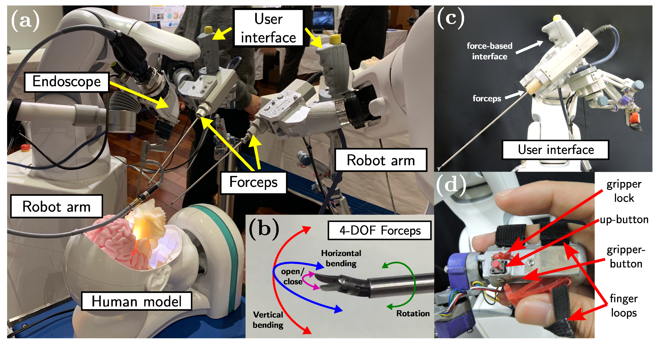
The proposed method is implemented on the system we have developed in [4] (see Figure 2a) composed of two 6-DOF industrial robot arms (VS-050, DENSO Corporation, Aichi, Japan), 4-DOF articulated forceps developed in [32], and user interfaces attached to the robot arms [4]. Each robotic unit has a total of 10-DOF, where 6-DOF are provided by the robot arm and 4-DOF are the contribution from the articulated forceps. The 4-DOF articulated forceps (see Figure 2b) comprises a shaft (diameter: 3.5 mm and length: 233 mm), a triangular-shaped gripper (length: 4 mm), and elastic elements to provide 3-DOF tip movement (bending in two directions and rotation around the axis) and the grasping function. The 4-DOF forceps tip motion is controlled by five DC motors (four motors for bending and grasping, and one motor for the rotation around the axis). The user interface comprises a vertical handle attached to a 6-axis force/torque sensor and an articulated serial link interface with a gripper handle (see Figure 2c). The vertical handle is used during the initial positioning and insertion/extraction of the articulated forceps, and the serial link interface is used for controlling the 4-DOF forceps and the robot arm during the suturing task. The gripper handle contains two push-buttons: one above the handle (up-button), and the second one placed inside the gripper (gripper-button) (see Figure 2d). The upper push-button enables the free motion control of the forceps tip and the gripper push-button activates the robot-assisted stitching mode.
2.1.2. Description of the Stitching Workspace Frames
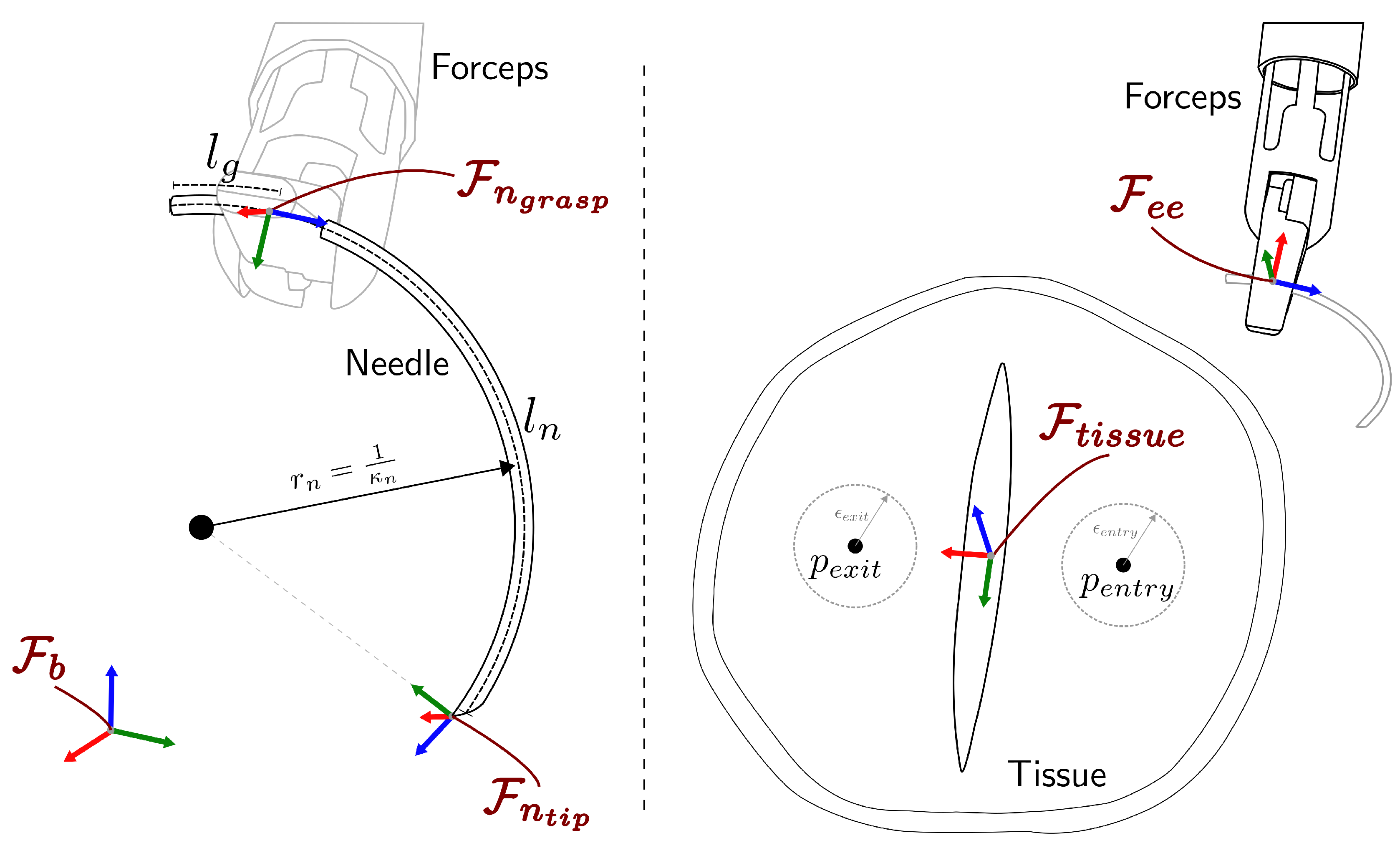
The coordinate frames for the robotic system are defined as shown in Figure 3, where represents the robot arm base frame, is the forceps tip frame, is the needle tip frame, is the frame associated to the needle grasping point, and corresponds to the tissue frame with the z-axis aligned to the tissue surface normal vector. We define relative coordinate frames as where b refers to the local frame and a refers to the reference frame. For notational convenience, a full pose (including position and orientation) in the frame a is denoted by as a combination of a position vector and a rotation matrix . When no reference frame is specified, it is assumed to be expressed in the base frame .
2.1.3. Algorithm Overview
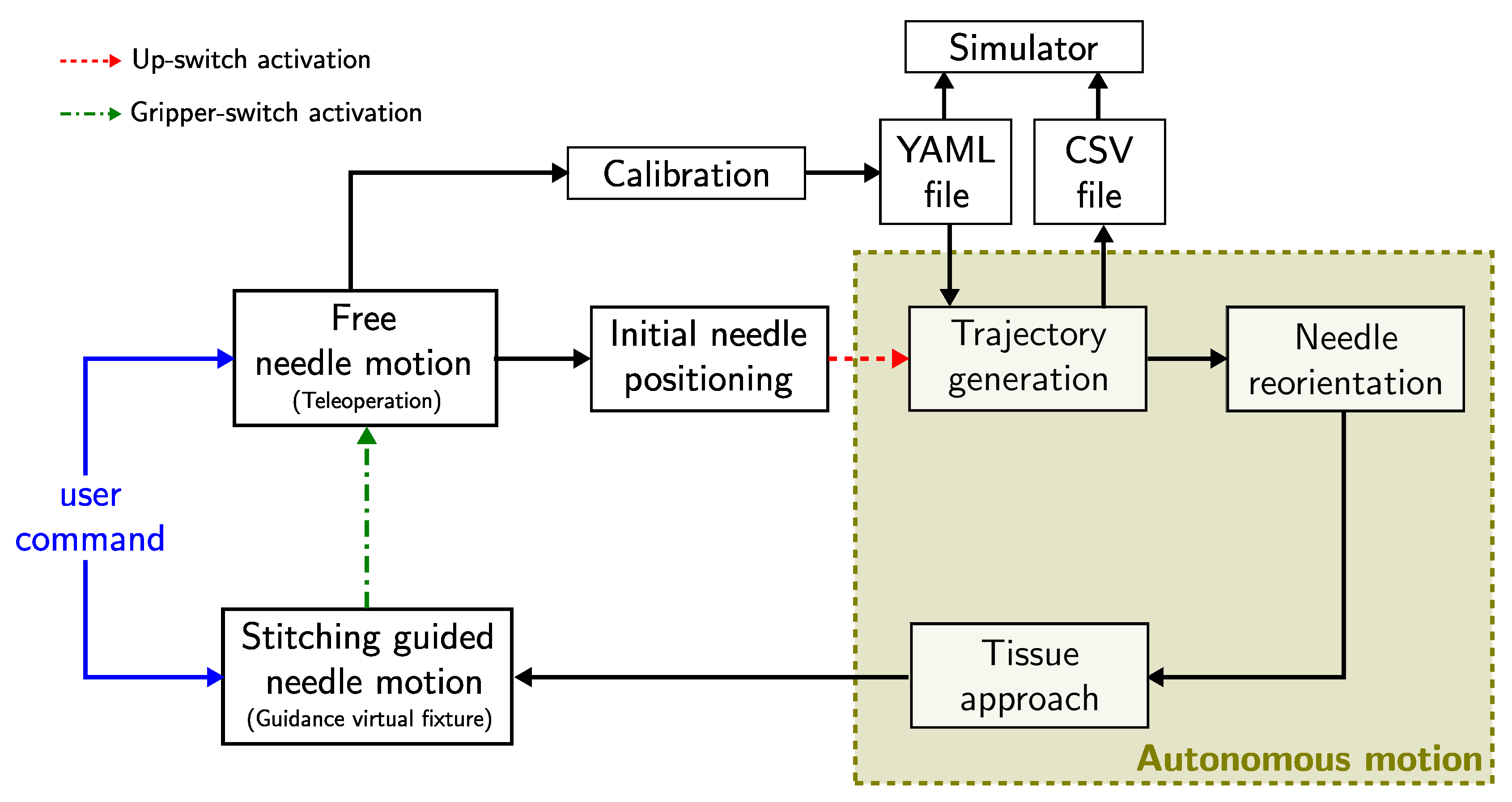
The high-level schematic overview of the proposed algorithm is shown in Figure 4. The proposed algorithm assumes that the forceps have been inserted into the nasal cavity through a remote center of motion (RCM) placed over the patient’s nostril [4], which is kept fixed by the constrained motion planner during the entire execution of the stitching task. First, the surgeon can command the forceps tip pose through the user interface (see Figure 2c) in a teleoperation mode. An initial calibration procedure can be performed to define the desired entry and exit points, and to determine the orientation plane of the tissue surface, by positioning the forceps tip over the desired points and recording them in a YAML file. The calibration file can be either generated online or retrieved from the previously recorded ones at any time during the trajectory generation process. During the teleoperation mode, the needle pose can be freely controlled. The surgeon places the needle in a suitable initial position and activates the robot-assisted stitching sequence by pressing the gripper-button located in the user interface handle. The robotic system will automatically generate an optimal trajectory to be followed by the needle tip during the stitching task. The generated trajectory is stored as a CSV file that is synchronized with a simulator for trajectory visualization. The optimal trajectory defines the desired initial needle tip pose close to the entry point over the tissue. The robot reorients the needle and approaches to the desired initial needle pose following the trajectory defined by a linear interpolation for the translational motion and a spherical linear interpolation for the rotational motion. When the needle is expected to be in an initial contact with the tissue, the robot stops and the stitching guided mode is activated. Now the robotic system follows a shared control scheme, in which the robot ensures that the needle tip pose (position and orientation) follows the optimal trajectory generated by the proposed algorithm, while the surgeon is in charge of the control of the insertion speed and direction of the motion. In this way, the optimal trajectory works as a virtual guidance constraint for the surgeon’s command. In case of changes in the trajectory generation parameters while performing the stitching sequence (e.g., changes on the desired entry or exit positions), the needle can be retracted along the optimal trajectory until full extraction, and a new trajectory can be generated with the updated parameters. Moreover, the surgeon can return to the free needle motion at any time by pressing the up-button located in the user interface handle. Then, the guidance virtual constraint is disabled and the surgeon can freely manipulate the needle pose.
2.2. Online Optimization-Based Trajectory Generation
Schulman et al. [33] proposed a non-convex sequential optimization for bevel-tip needle steering based on a curvature-constrained kinematic model. Sen et al. [17] extended this concept for curved needles. Building on this model, we formulate the stitching needle trajectory generation problem as a non-convex constrained optimization problem to be solved by penalized trust-region based sequential optimizations. The notation used in this paper is listed in Table 1.
2.2.1. Sequential Convex Programming
The goal of a general nonlinear programming problem (NLP) is to find an optimal set of parameters that minimizes a given cost function , while satisfying a set of equality and inequality constraints as
In general, NLPs are difficult to solve, but one of the most effective methods is the use of Sequential Convex Programming (SCP). The SCP method approximates a given NLP into convex subproblems (convex cost function, convex inequality constraints, and affine equality constraints) and sequentially update the solution estimation by solving the convex subproblem. NLP convexification can be performed by representing the cost function and constraints through Taylor series expansions around the current iteration u as
The solution of the subproblem generates a step to update the current solution towards the optimal solution. However, infeasibility is a common problem during an SCP that can be caused by a poor convexification or initial solution guess. One possible solution is to move the infeasible constraints into the objective function as penalties, which will converge to zero and ensure feasibility. Compared with other common penalty functions, the use of penalty provides an exact representation of the deviation from the constraint and numerical stability [34]. To avoid complications because of its non-smooth characteristic, it is common to implement penalties by using slack variables ( and t in Equation (3)) that do not modify the convexity of the original problem [35].
A trust-region method is also used to ensure global convergence. It is represented as a step boundary constraint , where is the trust region radius and p represents the p-norm used for the boundary conditions. The minimization problem is reformulated for a positive penalty as
To determine the acceptance of the current step, the SCP method uses the actual-to-predicted cost reduction ratio , defined by
where the merit function is given as
and the approximation of the objective function is given as
where represents a numerical approximation of the Hessian of the cost function , and . If is an accurate representation of the merit function , the trust region is expanded by a factor of and the control variable is updated. On the hand, if is rejected , is shrunk by a factor of . The sequential iteration stops when the convergence criteria are satisfied or the maximum number of iterations is exceeded. The outline of penalized trust region-based sequential optimization algorithm is shown in Algorithm 1.
| Algorithm 1: penalty trust region based sequential optimization. |
 |
2.2.2. Problem Definition
The stitching needle trajectory is discretized into N time intervals and represented as a set of needle tip poses at each time step , where each pose is defined as a homogeneous transformation matrix . The stitching trajectory planning problem can be defined as follows.
Input: The desired entry and exit points are given by the surgeon during the calibration process. The needle size and shape (, ), the suture depth , and the maximum needle curvature allowed are also provided.
Output: The set of desired needle tip poses .
Assumptions: It is assumed that the gripper holds the needle firmly so that needle deviations during the stitching task do not occur. We consider a flexible tissue where the friction forces produced during the tissue penetration can be neglected.
2.2.3. Optimization Model
The stitching needle trajectory generation problem is formulated as a constrained optimization problem as
Costs (Equation (7)):
The objective of penalizes longer trajectories to reduce tissue trauma. Additionally, needle deviation from an orthogonal pose with respect to the tissue surface is also penalized during the needle insertion with and extraction to facilitate tissue penetration. The concrete forms of these cost functions are given as
Stitching kinematic constraints (Equation (8)):
We use the curvature constrained kinematic model proposed by Sen et al. [17] for curved needles. At each time step, the needle is inserted following a fixed length b with a curvature , where is the needle natural curvature and are local curvature changes applied for needle reorientation at the time step t. The transformation between consecutive needle poses can be represented as a twist , composed of a translational motion b along the needle tip tangent vector, and a rotational motion along the normal vector to the needle’s plane. The corresponding twist in the base frame can then be computed as , with the adjoint matrix defined as .
The lie algebra exponential and logarithmic mapping in [36] are used to represent the kinematic constraint at each time step.
Desired Entry/Exit Port Constraints (Equations (9) and (10)):
The generated trajectory entry/exit points should be within a tolerance from the desired entry/exit point, respectively.
Needle Constraints (Equation (11)):
The total trajectory length including the distance for the forceps to hold the needle should be less than the needle length .
Suture depth constraint (Equation (12)):
The trajectory should have a minimum depth to ensure a proper tissue penetration.
Needle reorientation constraints (Equations (13)–(15)):
Small curvature changes are allowed from the needle natural curvature , but are bounded by and limited to be monotonically decreasing.
2.3. Constrained Motion Planning
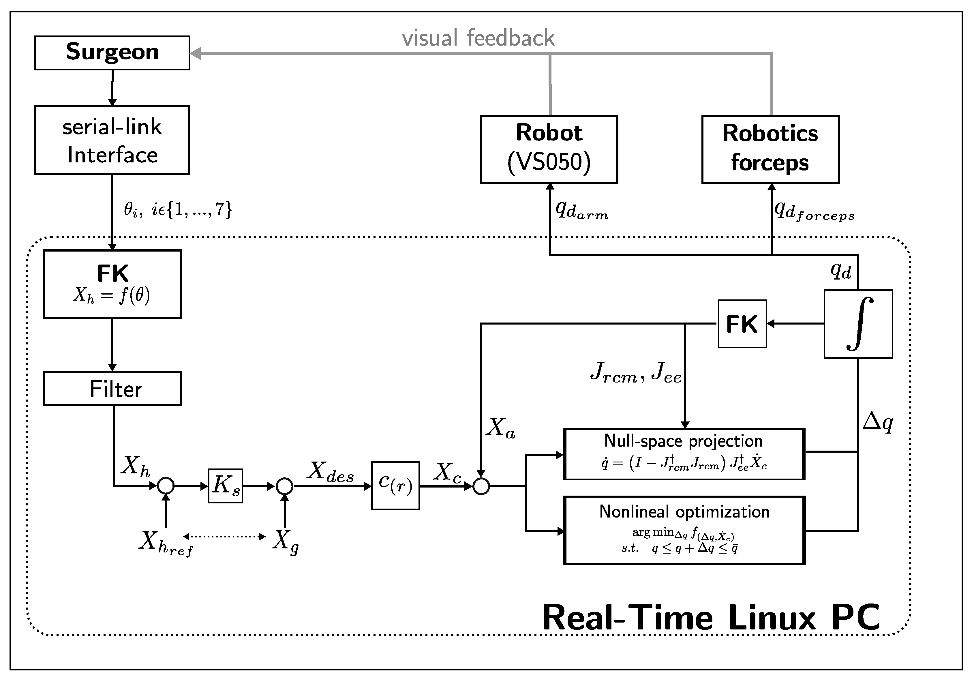
EES constrains the motion of the surgical tools along the nostril and nasal cavity. It is important to ensure safe tool manipulation by implementing a remote center of motion constraint over the nostril. We propose a constrained motion planning based on a guidance virtual fixture along the optimally generated needle trajectory, and a concurrent constrained inverse kinematic solver implementation based on a task-priority IK method and a nonlinear programming IK method. Figure 5 depicts a block diagram of the proposed constrained motion control. Given a surgeon’s pose command through the serial-link interface , the scaled desired end-effector pose is computed. A guidance virtual fixture constrains the needle tip motion along a continuous optimal trajectory and generates the constrained end-effector pose . Then, a concurrent IK solver performs a simultaneous prioritized Jacobian-based inverse kinematics and a constrained nonlinear optimization inverse kinematics. The task-priority IK can find a solution faster, but joint limits and higher priority tasks may produce convergence failures. On the other hand, nonlinear optimization takes longer to compute, but can better handle joint limits and additional constraints. When one of them finds an acceptable solution, the other IK solver is stopped, and the computed joint command is distributed between the robot arm () and the articulated forceps ().
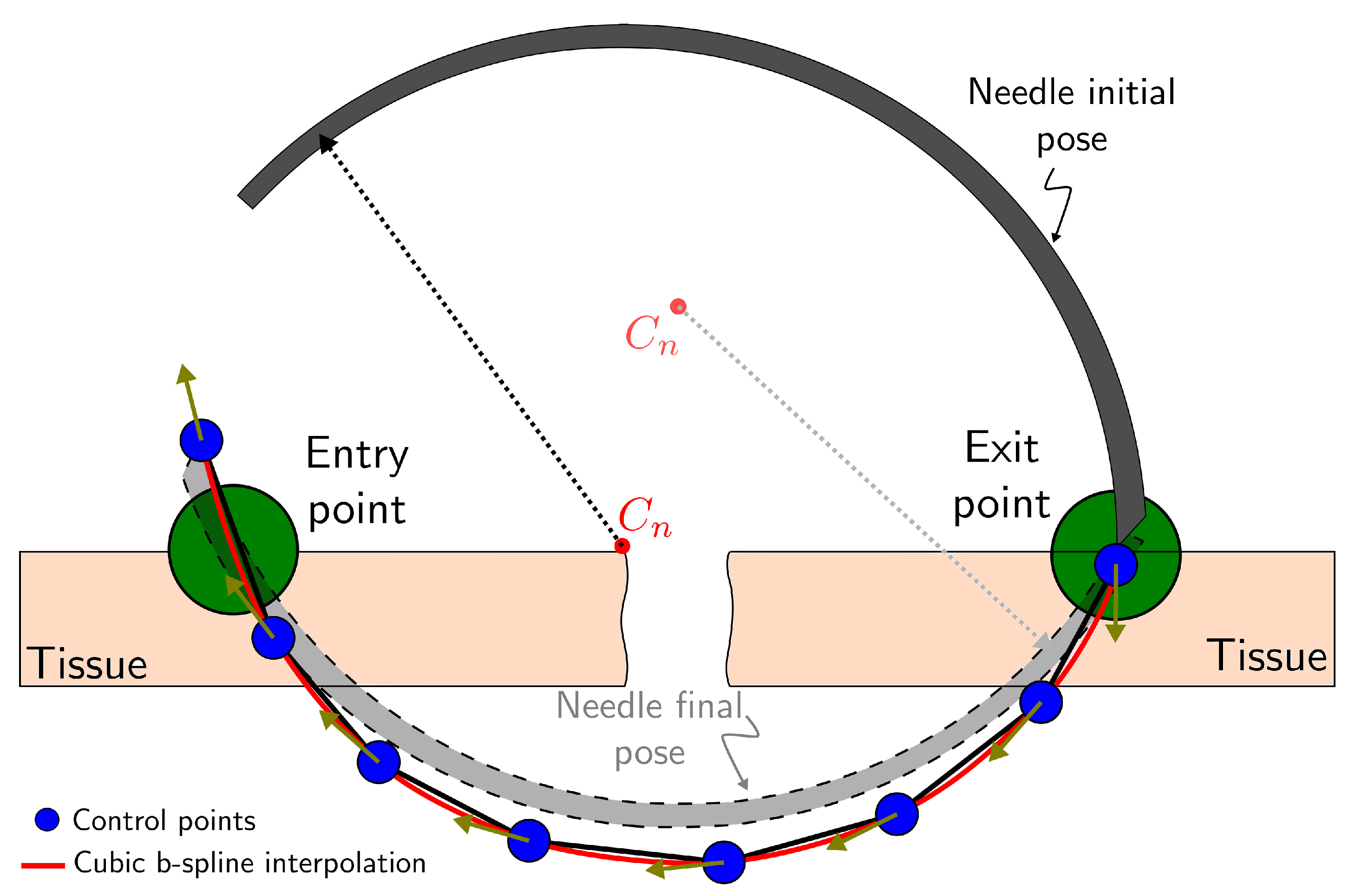
2.3.1. Guidance Virtual Fixture
A continuous and differentiable position and orientation trajectory is generated by cubic b-spline interpolation of the control points from the optimal stitching needle trajectory obtained in Section 2.2 (see Figure 6) as
where are the b-spline basis functions and are the uniformly distributed knots.
The continuous trajectory is then used as reference curve for a hard virtual fixture [37]. The desired position obtained from the user interface command is projected onto the normalized tangent direction of the reference curve with , and scaled by to update the interpolation parameter as
The constrained pose is then computed by evaluating .
2.3.2. Task-Priority Inverse Kinematics
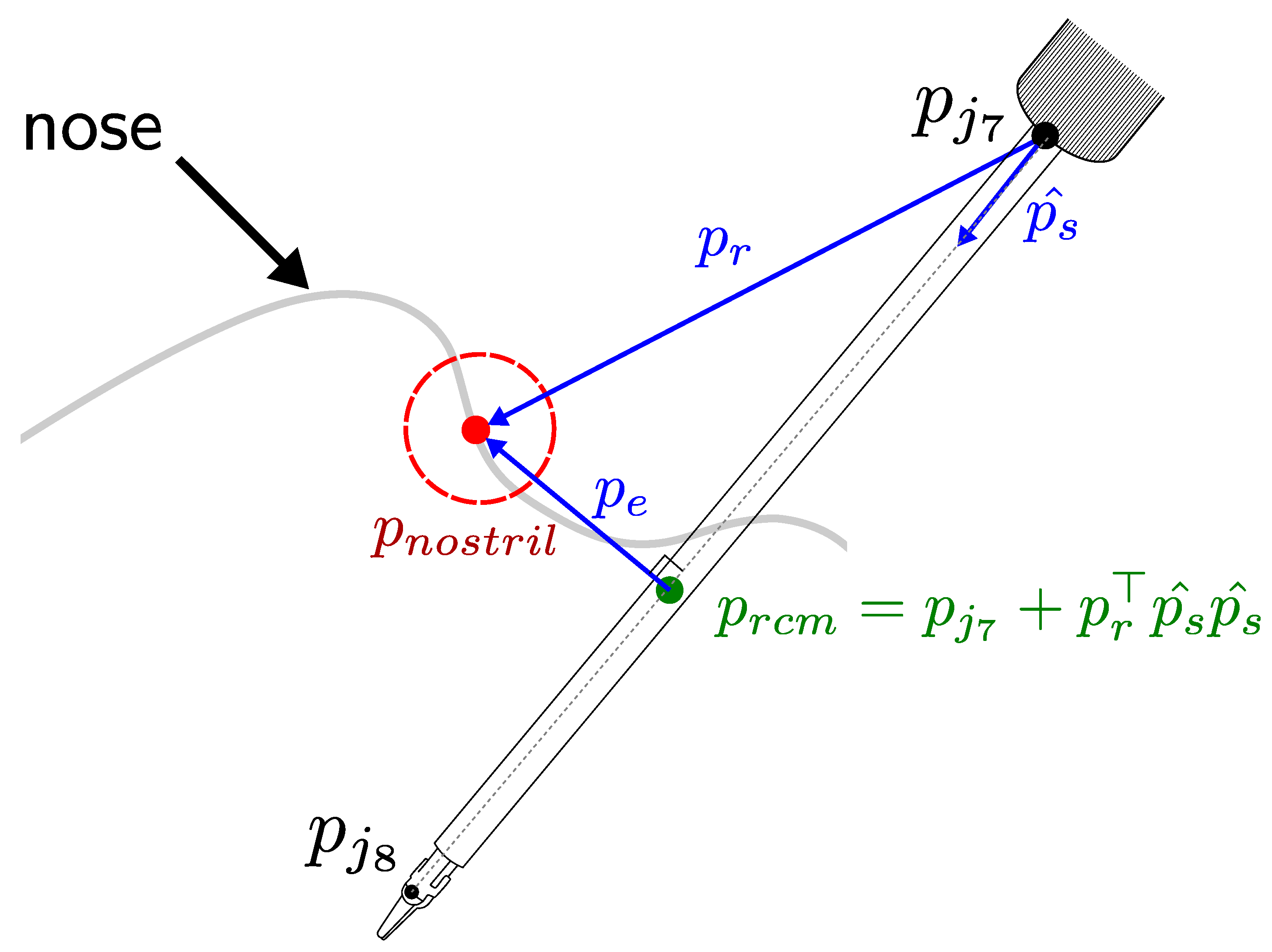
The RCM constraint can be defined as a higher priority task in a hierarchical null-space projection method [38]. Based on this, Azimian et al. [39] proposed an RCM implementation by projecting the end-effector tracking task over the null space of the RCM task. Sandoval et al. [40] proposed a similar RCM implementation for torque-controlled redundant manipulator, but based on the RCM distance to a trocar that does not depend on the insertion velocity. We define the RCM constraint problem also using a prioritized Jacobian method but defining the RCM position as the nostril projection onto the forceps shaft.
Figure 7 depicts the variables used in the RCM Jacobian computation. The unit vector with represents the direction of the forceps shaft and is the vector between the nostril and the base of the forceps shaft. We can compute the RCM position by
Then we can differentiate :
By matrix differentiation, we obtain the RCM Jacobian as
where
We assume the constrained motion planning is initialized with the forceps shaft over the nostril, so that the RCM Jacobian velocity must be zero . By projecting the end-effector tracking task over the null space of the RCM task we can compute the joint velocity command as
2.3.3. Nonlinear Optimization Inverse Kinematics
The previous prioritized Jacobian-based IK can be susceptible to convergence failure when close to joint limits. Beeson et al. [41] proposed a concurrent inverse kinematics library for generic inverse kinematic (TRAC-IK) that addresses the convergence problem by simultaneously executing a nonlinear optimization based IK solver. In a similar way, we propose a constrained nonlinear optimization problem to be executed simultaneously with our previous task-priority IK solver.
We define the constrained nonlinear optimization problem as
where are the positive coefficients, is the Cartesian position end-effector error, is the orientation error expressed using the logarithmic mapping, and is the RCM position error. By increasing the value of over the other coefficients, we can prioritize the minimization of an RCM error.
3. Experiments and Discussion
3.1. Implementation Details
The proposed methodology is implemented on a 2.4 GHz Core i7 CONTEC computer running Linux (Ubuntu 16.04, Canonical) with real-time patches (RT-PREEMPT) and the Robot Operating System (ROS) framework on top of it. The control loop runs at a rate of 125 Hz in synchronous mode with the industrial robot arm controller. In each cycle, the current robot pose is updated, and then the target robot pose is computed and sent to the robot arm and the articulated forceps controllers [4]. The rigid body kinematic is implemented by using the template library Pinocchio [42], and the optimization framework is built on CasADi [43], which allows C-code generation to speed up the optimization process. The quadratic programming solver used for the stitching needle trajectory generation is the Gurobi Optimizer [44]. For the nonlinear optimization based IK, we use the IPOPT solver [45].
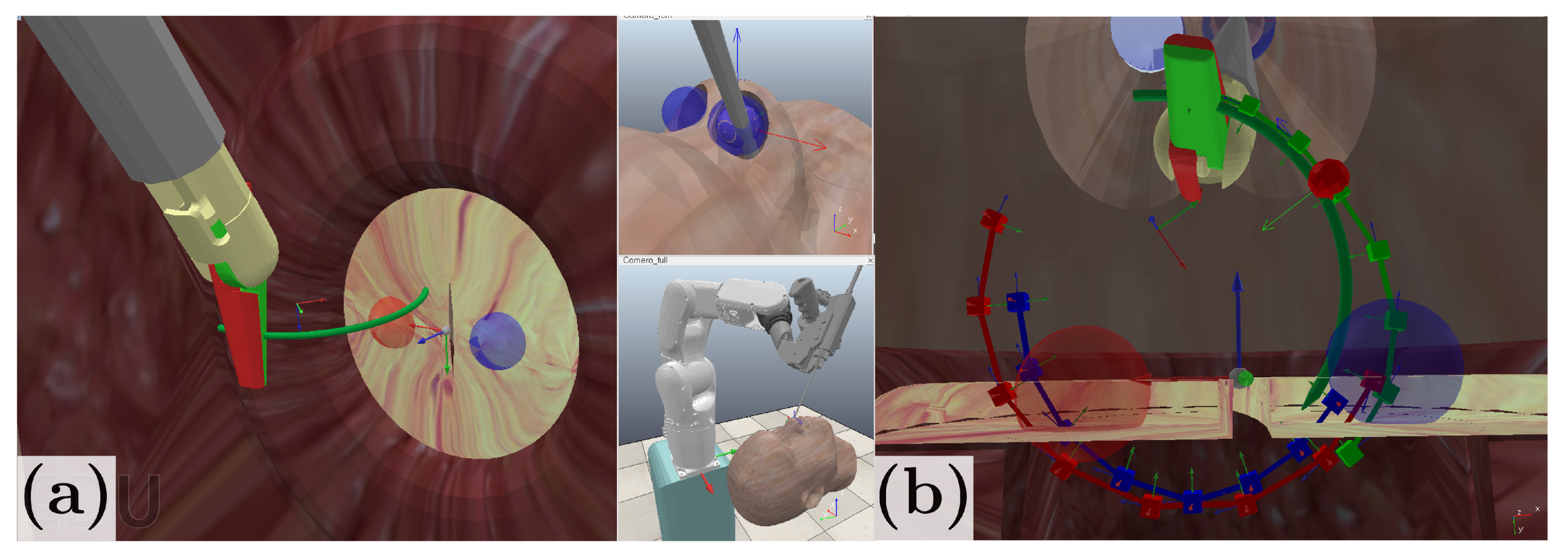
3.2. Simulation Environment
To evaluate the performance of our proposed scheme, we initially validate the trajectory generation and constrained motion control in a simulation environment developed on CoppeliaSim EDU V4.1 [46], in which we model the nostril constraint and simulate the robot kinematics. Figure 8a shows the simulation environment created for system implementation. In Figure 8b, the desired entry point and exit points are represented with a blue and red sphere, respectively, with a 1.5 mm tolerance radius. An initial needle trajectory is provided as half-turn trajectory that follows the natural needle curvature and is shown as a red curve. The blue curve corresponds to the optimal trajectory obtained from the sequential convex optimization, and the green curve corresponds to the forceps tip reference trajectory. In simulation conditions, the stitching needle trajectory generation takes approximately 500 ms and the maximum RCM deviation is 1 mm.
3.3. Stitching Experiments
We conduct a stitching experiment to validate the performance our system in a physically realistic environment, and compare three stitching modes:
- Manual: by using conventional forceps for endoscopic endonasal surgery.
- Robot-assisted: by using the proposed method. The system generates the optimal trajectory and constrains the needle pose.
- Autonomous: the robot starts in a fixed initial pose and executes the stitching task without human assistance.
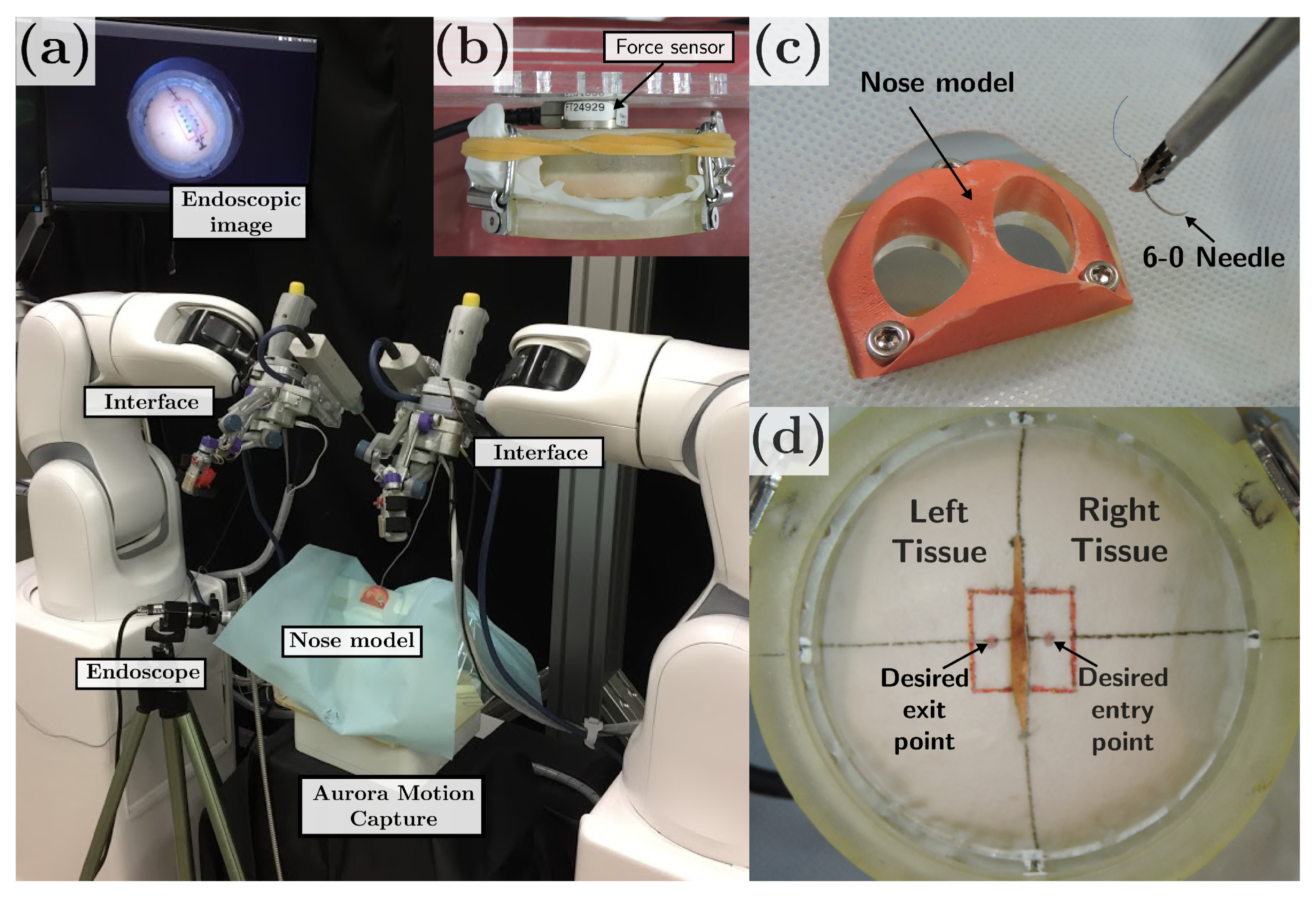
The experimental setup is presented in Figure 9. It comprises a 3D printed nose model and an acrylic platform for the stitching testbed. A six-axis force/torque sensor (Nano17, ATI Industrial Automation, North Carolina, USA) is placed behind the elastic tissue to measure the compression and shear forces applied to the tissue during the stitching task (see Figure 9b). We assumed the compression forces to be perpendicular to the tissue surface and aligned to the z-axis of the force sensor, whereas the shear forces are tangential to the tissue surface. For the force analysis, we use the root sum square (RSS) of the resulting forces given by the square root of the sum of squares of the forces in each direction measured by the force sensor (Equation (28)). The forces are sampled at a frequency of 1 kHz and the testbed’s weight related forces are subtracted.
A magnetic motion capture system (Aurora, Northern Digital Inc., Ontario, Canada) is used to record the motions of the surgical instrument for both the manual and robot operation. A rigid endoscope (, 2.7 mm diameter) is used for visualization and targeting the area of interest.
The participants were asked to perform a stitching task. The task consisted of grasping a 6-0 surgical needle and puncture an elastic tissue, on which the desired entry/exit point were marked (see Figure 9d). In the manual stitching mode, the participants were asked to follow a three-step procedure: (1) puncture the right tissue from the marked point, (2) penetrate the right tissue until the needle tip is placed under the left tissue, and (3) puncture the left tissue from underneath. In the robot-assisted stitching mode, the participants were asked to position the needle in a suitable initial position and command the needle insertion speed (0–0.5 mm/s) and direction through the user interface, while the robot constrained the needle pose along the reference trajectory and kept the RCM constraints. In both cases, assistance from the surgical tool on the left hand was also allowed to tighten the left tissue, but no needle manipulation assistance was allowed. The autonomous stitching mode was performed without human assistance, and the needle insertion speed was set at the maximum allowed (0.5 mm/s). In all the stitching modes, the trial starts with the needle grasped by the surgical tool and placed about 2 cm above the center frame of the tissue.
Seven subjects between the ages of 25 and 35 who had no previous surgical training took part in this experiment. Before the experiment, each participant was instructed about the procedure and practiced for up to 10 min until they were familiarized with the operation. All subjects were given informed consent before they participated in the study. This study was approved by the Ethical Research Committee of Nagoya University.
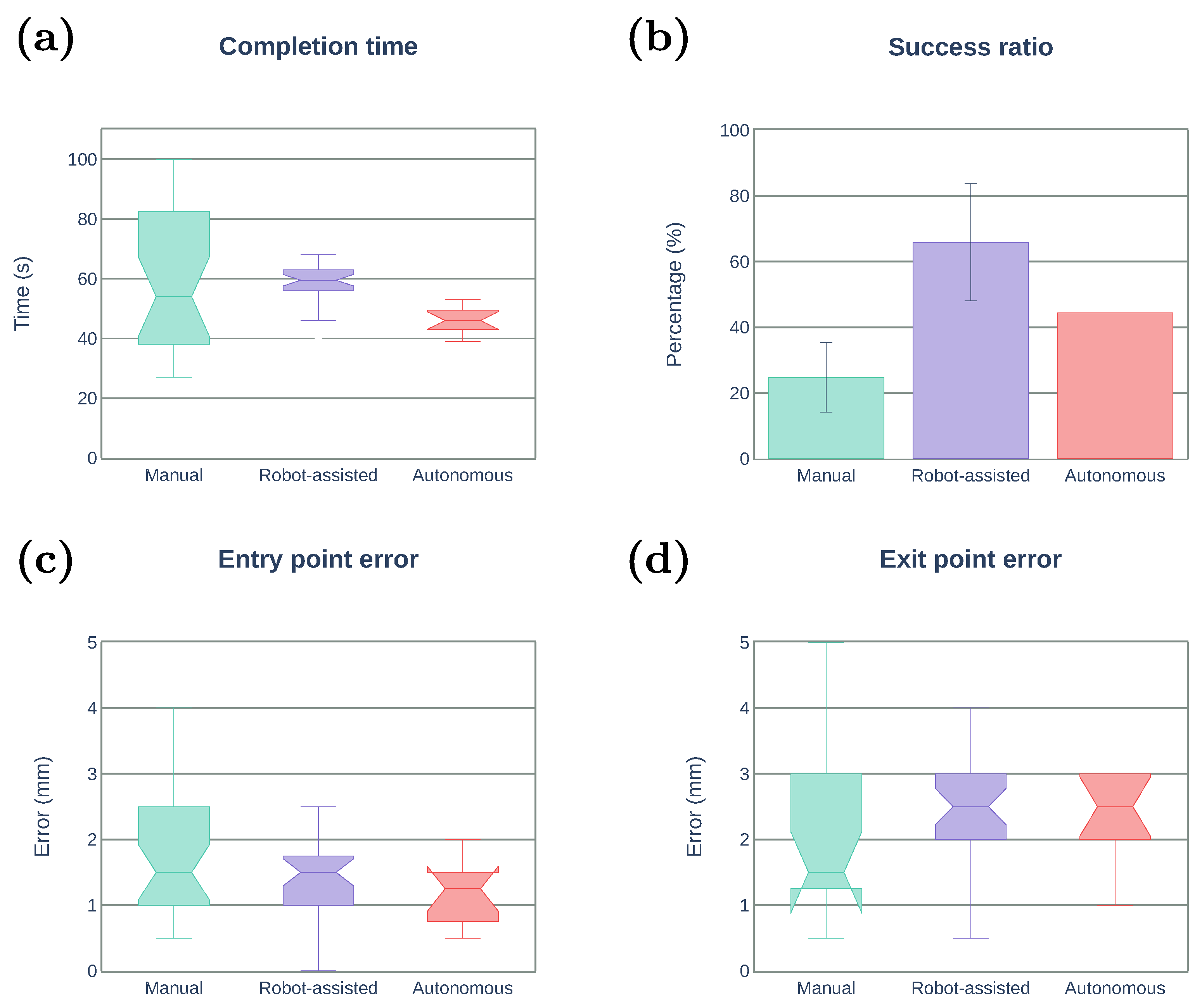
We evaluate participants’ performance using the following metrics:
- Task completion time (s): the total time in which participants performed the task.
- Success ratio (%): the percentage of succeed stitching from the total number of attempts.
- Entry point error (mm): the Euclidean distance between the desired entry point and the actual entry point.
- Exit point error (mm): the Euclidean distance between the desired exit point and the actual exit point.
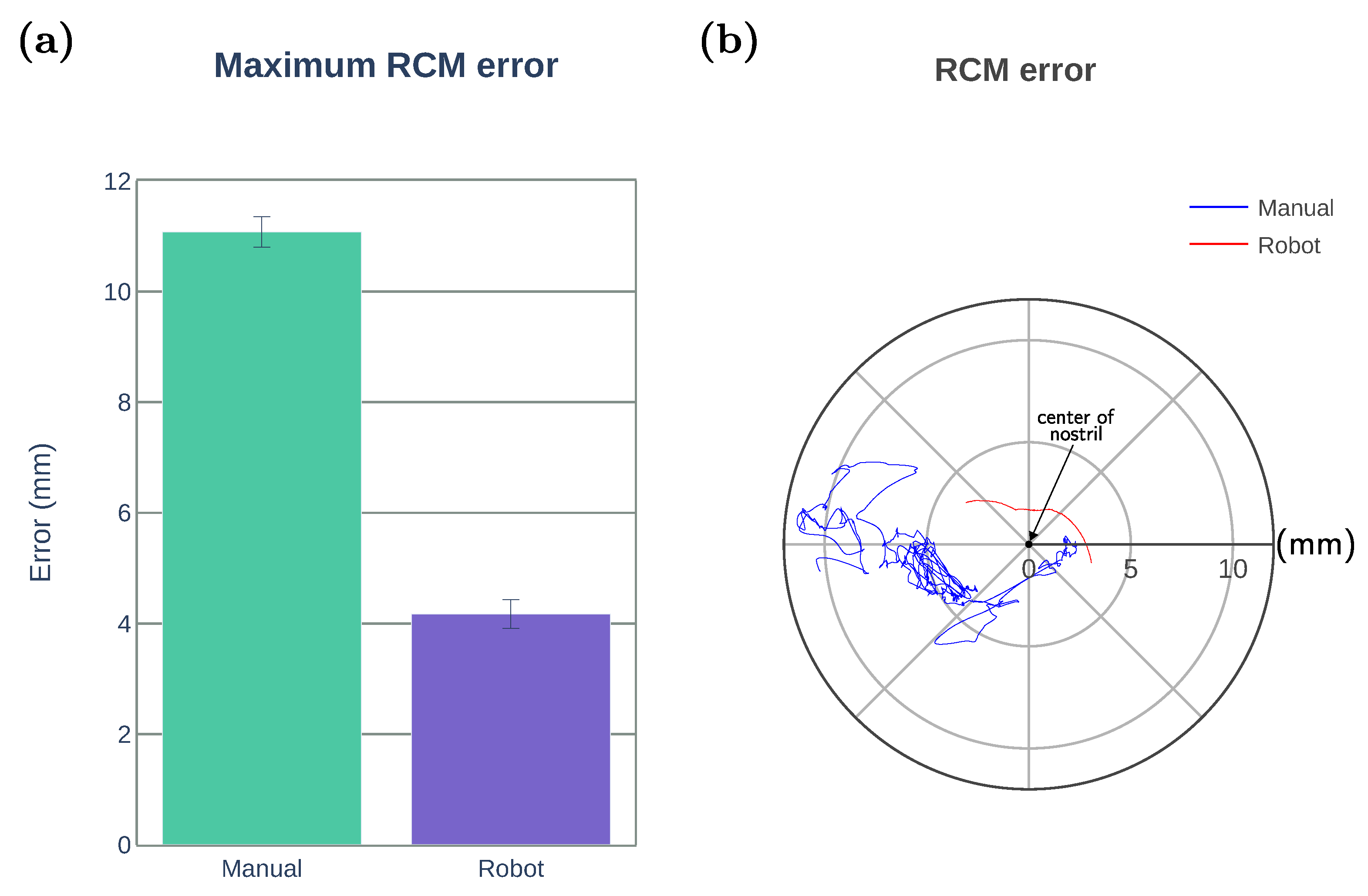
- Maximum RCM error (mm): the maximum Euclidean distance between the RCM position and the center of the nostril.
- Maximum RSS force (N): the maximum RSS force applied on the tissue.
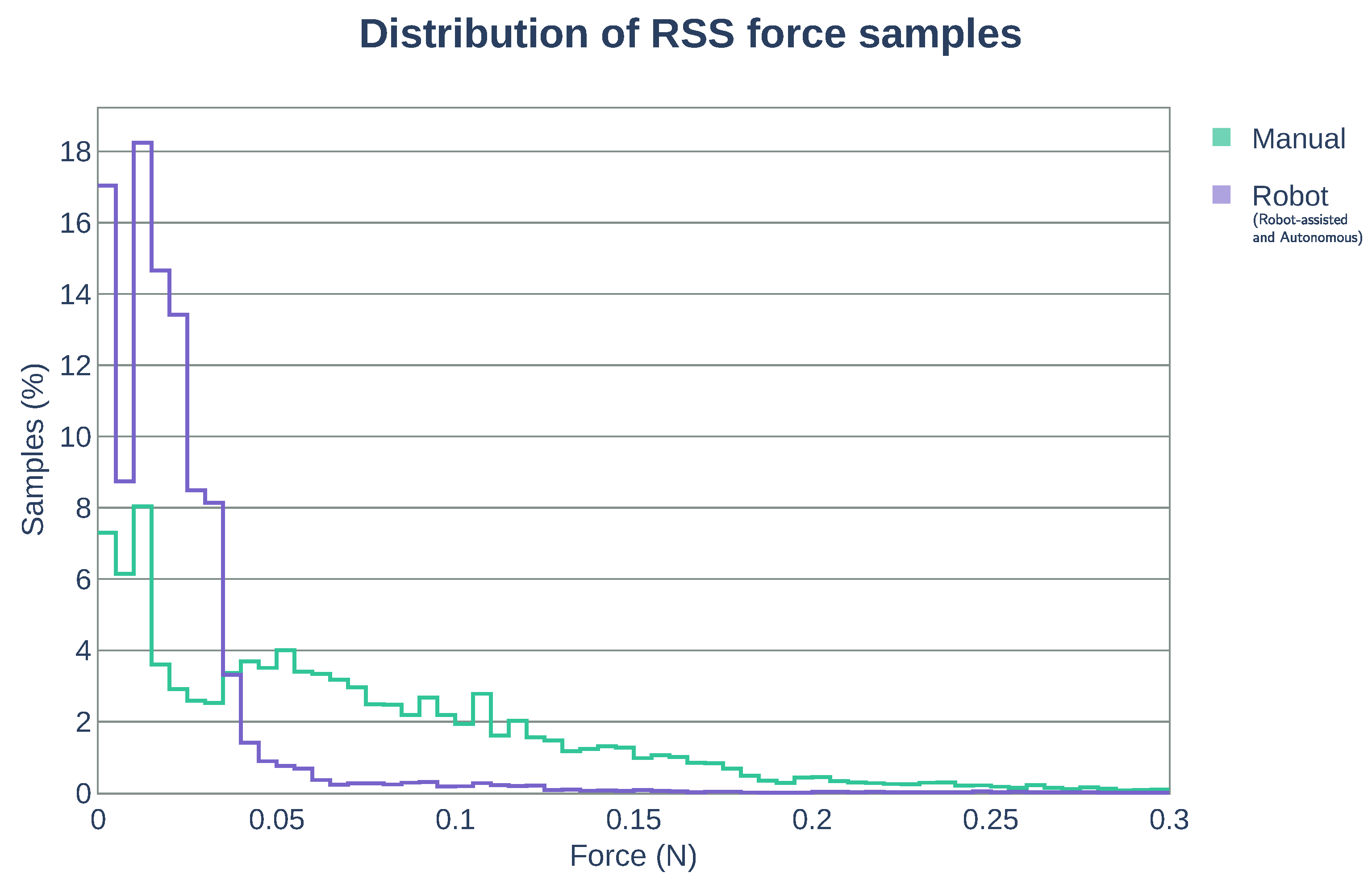
- Distribution of RSS force samples: graphical representation of the number of RSS force measurements within equally distributed force intervals with respect to the total number of RSS force samples obtained during the stitching task.
Figure 10 summarizes the results obtained for the three stitching modes (manual, robot-assisted, and autonomous). The number of trials and success ratio per subject are presented in Table 2, Table 3 and Table 4. Note that the task completion time, entry point error, and exit point error are computed only for the successful trials. Figure 10a depicts the task completion time. The reliability of using the robotic system is evident as the standard deviation is greatly reduced compared with the manual operation. The median time for the robot-assisted is about 25% longer than that of the autonomous mode. However, there was no significant improvement with respect to the manual operation. Figure 10b shows the success ratio of the stitching task, where the robot-assisted mode achieved the success ratio of 65.3%, much higher than that of the autonomous mode (43.8%) and the manual operation (25.4%). Needle–tissue interaction forces arising at the needle tip may induce undesired changes in the needle orientation, which could result in a failed attempt to penetrate the tissue. Unlike the autonomous mode where the speed is fixed, the robot-assisted mode allows the user to freely control the insertion speed and reduce the effect of such interaction forces. Moreover, in the robot-assisted mode, the user can also retract the needle along the optimal trajectory if proper penetration is not achieved (e.g., because of tissue deformation). The needle can be pulled back and reinserted without the need of recomputing the optimal trajectory as long as the needle orientation with respect to the forceps tip has not changed. As a consequence, the robot-assisted mode can require additional time to complete the task compared with the autonomous method. Therefore, a trade-off exists between assuring proper tissue penetration and the stitching completion time. Figure 10c,d depicts the entry/exit point error. The autonomous mode showed the smaller entry point error among the three cases, but no improvement in exit point error can be observed when using the robotic system. This is expected, as the stitching trajectory generation algorithm will try to keep the changes in the curvature bounded to facilitate tissue penetration and reduce tissue deformation, which can produce a larger deviation from the desired exit point. By increasing the allowed range of curvature changes, the exit error is expected to be reduced, but higher forces might be generated.
We evaluate the constrained motion planning performance by the maximum RCM error defined as the minimum distance between the nostril and forceps shaft. The RCM constraint implemented for the robotic operation (including robot-assisted and autonomous modes) was able to keep the maximum RCM error below 4.2 mm as shown in Figure 11a. Figure 11b illustrates an example of the forceps displacement from the center of the nostril during task execution by one of the participants. The blue line represents the position of the forceps shaft intersection with the nostril plane for the manual operation, and the red line represents the intersection trajectory obtained when using the robotic system.
We also measured the forces applied during the stitching task to evaluate the possibility of potential tissue trauma. Table 5 summarizes the maximum RSS force applied. The use of the robotic system demonstrates a reduction of approximately 70% of the maximum force compared with manual operation. During the manual operation, frequent undesired collision of the forceps on the tissue occurred because of the lack of the depth information by the 2D endoscopic visualization. Figure 12 shows the distribution of the RSS force samples contained within the force intervals of 0.005 N. The larger the number of bins close to 0 N, the smaller amount of continuous force applied to the tissue (less potential damage). With the use of the robot system (robot-assisted and autonomous modes), approximately 90% of the RSS force samples are within the range of [0, 0.05] N, while for the manual operation, the 90% of the samples are found within the range of [0, 0.15] N. The use of the robotic system reduced effectively the range of forces applied over the tissue in approximately 66%.
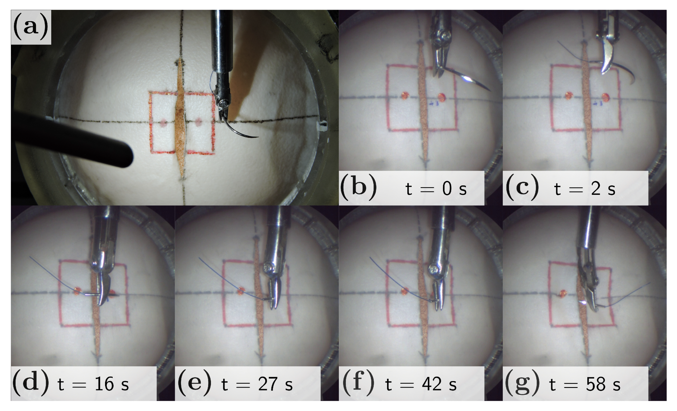
Figure 13a depicts the needle positioned into the stitching workspace. An example of the complete stitching sequence achieved with the robot-assisted mode is shown in Figure 13b–g, with a total duration of 58 s. The user initially placed the needle close to the entry point (t = 0, Figure 13b) and activates the robot-assisted stitching sequence. An optimal trajectory is generated with an initial needle tip pose. The robot reorients the needle (Figure 13c) and approaches to the entry point located over the tissue (Figure 13d). Under the user control, the needle penetrates the right tissue (Figure 13e), commands the needle under the tissue toward the exit point (Figure 13f), and finally penetrates the left tissue from underneath (Figure 13g).
4. Conclusions
In this paper, we have proposed an optimization-based trajectory generation method for robot-assisted stitching based on a sequential convex optimization to find the optimal needle trajectory and a dual concurrent IK solver to constrain the surgical tool around the nostril. The trajectory generation algorithm was capable of generating optimal trajectory subject to the suturing requirements. The surgeon can regenerate the trajectory online through the user interface. Integrating two constrained IK methods allowed us to achieve the convergence of the solution and meet time constraints. We compared the performance of our system with a manual stitching operation and an autonomous operation. The results showed a noticeable improvement in the stitching success ratio and reduction of the force interaction with the tissue. In the robot-assisted mode, the surgeon can control the initial positioning and insertion speed, which avoids potential rotations in the needle and ensure a proper initial tissue penetration. However, the task completion time did not significantly improve compared with the manual mode. Although the robot task completion time could be reduced by increasing the maximum speed allowed for the needle, it might reduce the insertion success. In addition, the interaction force distribution showed that the use of robot reduced about 70% of the forces showed in a manual stitching task. This is important to avoid any potential tissue trauma. The results also showed that the proposed system could safely constrain the motion of the articulated multi-DOF forceps for an endoscopic endonasal surgical stitching. Future work will focus on the use of visual feedback for dynamic generation of virtual constraints and extend the proposed method into other surgical tasks such as knot tying.
Author Contributions
Conceptualization, J.N. and Y.H.; methodology, J.C.; software, J.C.; experiments, J.C.; writing—original draft preparation, J.C.; writing—review and editing, J.N., T.A., and Y.H.; supervision, J.N., T.A., and Y.H.; project administration, Y.H.; funding acquisition, Y.H. All authors have read and agreed to the published version of the manuscript.
Funding
This work was funded by ImPACT Program of Council for Science, Technology and Innovation (Cabinet Office, Government of Japan).
Institutional Review Board Statement
The study was conducted according to the guidelines of the Declaration of Helsinki, and approved by the Ethical Research Committee of Nagoya University.
Informed Consent Statement
Informed consent was obtained from all subjects involved in the study.
Data Availability Statement
The data presented in this study are available on request from the corresponding author.
Acknowledgments
We thank Murilo Marinho at the University of Tokyo for his assistance on real-time control implementation and Tsuyoshi Ueyama at Denso Corporation for his help on the robot hardware setup.
Conflicts of Interest
The authors declare no conflict of interest.
References
- Garcia-Ruiz, A.; Gagner, M.; Miller, J.H.; Steiner, C.P.; Hahn, J.F. Manual vs Robotically Assisted Laparoscopic Surgery in the Performance of Basic Manipulation and Suturing Tasks. Arch. Surg. Chic. 1998, 133, 957–961. [Google Scholar] [CrossRef]
- Ruurda, J.P.; Broeders, I.A.M.J.; Pulles, B.; Kappelhof, F.M.; van der Werken, C. Manual robot assisted endoscopic suturing: Time-action analysis in an experimental model. Surg. Endosc. 2004, 18, 1249–1252. [Google Scholar] [CrossRef]
- Kranzfelder, M.; Staub, C.; Fiolka, A.; Schneider, A.; Gillen, S.; Wilhelm, D.; Friess, H.; Knoll, A.; Feussner, H. Toward increased autonomy in the surgical OR: Needs, requests, and expectations. Surg. Endosc. 2013, 27, 1681–1688. [Google Scholar] [CrossRef] [Green Version]
- Colan, J.; Nakanishi, J.; Aoyama, T.; Hasegawa, Y. A Cooperative Human-Robot Interface for Constrained Manipulation in Robot-Assisted Endonasal Surgery. Appl. Sci. 2020, 10, 4809. [Google Scholar] [CrossRef]
- Kapoor, A.; Li, M.; Taylor, R.H. Spatial Motion Constraints for Robot Assisted Suturing Using Virtual Fixtures. In Proceedings of the 2005 International Conference on Medical Image Computing and Computer-Assisted Intervention, Palm Springs, CA, USA, 26–29 October 2005; pp. 89–96. [Google Scholar] [CrossRef] [Green Version]
- Knoll, A.; Mayer, H.; Staub, C.; Bauernschmitt, R. Selective automation and skill transfer in medical robotics: A demonstration on surgical knot-tying. Int. J. Med. Robot. Comput. Assist. Surg. 2012, 8, 384–397. [Google Scholar] [CrossRef] [PubMed] [Green Version]
- Osa, T.; Sugita, N.; Mitsuishi, M. Online Trajectory Planning in Dynamic Environments for Surgical Task Automation. In Proceedings of the 2014 Robotics: Science and Systems Conference, Berkeley, CA, USA, 12–16 July 2014; pp. 1–9. [Google Scholar] [CrossRef]
- Van den Berg, J.; Miller, S.; Duckworth, D.; Hu, H.; Wan, A.; Fu, X.-Y.; Goldberg, K.; Abbeel, P. Superhuman Performance of Surgical Tasks by Robots using Iterative Learning from Human-Guided Demonstrations. In Proceedings of the 2010 IEEE International Conference on Robotics and Automation, Anchorage, AK, USA, 3–7 May 2010; pp. 2074–2081. [Google Scholar] [CrossRef]
- Kang, H.; Wen, J.T. Autonomous suturing using minimally invasive surgical robots. In Proceedings of the 2000 IEEE International Conference on Control Applications, Anchorage, AK, USA, 27 September 2000; pp. 742–747. [Google Scholar] [CrossRef]
- Chow, D.-L.; Newman, W. Trajectory Optimization of Robotic Suturing. In Proceedings of the 2015 IEEE International Conference on Technologies for Practical Robot Applications, Woburn, MA, USA, 11–12 May 2015; pp. 1–6. [Google Scholar] [CrossRef]
- Nageotte, F.; Zanne, P.; Doignon, C.; de Mathelin, M. Stitching Planning in Laparoscopic Surgery: Towards Robot-assisted Suturing. Int. J. Robot. Res. 2009, 28, 1303–1321. [Google Scholar] [CrossRef]
- Liu, T.; Cavusoglu, M.C. Needle Grasp and Entry Port Selection for Automatic Execution of Suturing Tasks in Robotic Minimally Invasive Surgery. IEEE Trans. Autom. Sci. Eng. 2016, 13, 552–563. [Google Scholar] [CrossRef] [PubMed]
- Staub, C.; Osa, T.; Knoll, A.; Bauernschmitt, R. Automation of Tissue Piercing using Circular Needles and Vision Guidance for Computer Aided Laparoscopic Surgery. In Proceedings of the 2010 IEEE International Conference on Robotics and Automation, Anchorage, AK, USA, 3–7 May 2010; pp. 4585–4590. [Google Scholar] [CrossRef] [Green Version]
- D’Ettorre, C.; Dwyer, G.; Du, X.; Chadebecq, F.; Vasconcelos, F.; Momi, E.D.; Stoyanov, D. Automated pick-up of suturing needles for robotic surgical assistance. In Proceedings of the 2018 IEEE International Conference on Robotics and Automation, Brisbane, QLD, Australia, 21–25 May 2018; pp. 1370–1377. [Google Scholar] [CrossRef] [Green Version]
- Iyer, S.; Looi, T.; Drake, J. A Single Arm, Single Camera System for Automated Suturing. In Proceedings of the 2013 IEEE International Conference on Robotics and Automation, Karlsruhe, Germany, 6–10 May 2013; pp. 239–244. [Google Scholar] [CrossRef]
- Pedram, S.A.; Ferguson, P.; Ma, J.; Dutson, E.; Rosen, J. Autonomous Suturing via Surgical Robot: An Algorithm for Optimal Selection of Needle Diameter, Shape, and Path. In Proceedings of the 2017 IEEE International Conference on Robotics and Automation, Singapore, 29 May–3 June 2017; pp. 2391–2398. [Google Scholar] [CrossRef]
- Sen, S.; Garg, A.; Gealy, D.V.; McKinley, S.; Jen, Y.; Goldberg, K. Automating Multi-Throw Multilateral Surgical Suturing with a Mechanical Needle Guide and Sequential Convex Optimization. In Proceedings of the 2016 IEEE International Conference on Robotics and Automation, Stockholm, Sweden, 16–21 May 2016; pp. 4178–4185. [Google Scholar] [CrossRef] [Green Version]
- Jackson, R.C.; Cavusoglu, M.C. Needle Path Planning for Autonomous Robotic Surgical Suturing. In Proceedings of the 2013 IEEE International Conference on Robotics and Automation, Karlsruhe, Germany, 6–10 May 2013; pp. 1669–1675. [Google Scholar] [CrossRef] [Green Version]
- Watanabe, K.; Kanno, T.; Ito, K.; Kawashima, K. Single-Master Dual-Slave Surgical Robot With Automated Relay of Suture Needle. IEEE Trans. Ind. Electron. 2018, 65, 6343–6351. [Google Scholar] [CrossRef]
- Adhami, L.; Coste-Maniere, E. Optimal planning for minimally invasive surgical robots. IEEE Trans. Robot. Autom. 2003, 19, 854–863. [Google Scholar] [CrossRef]
- Kehoe, B.; Kahn, G.; Mahler, J.; Kim, J.; Lee, A.; Lee, A.; Nakagawa, K.; Patil, S.; Boyd, W.D.; Abbeel, P.; et al. Autonomous Multilateral Debridement with the Raven Surgical Robot. In Proceedings of the 2014 IEEE International Conference on Robotics and Automation, Hong Kong, China, 31 May–7 June 2014; pp. 1432–1439. [Google Scholar] [CrossRef] [Green Version]
- Murali, A.; Sen, S.; Kehoe, B.; Garz, A.; McFarland, S.; Patil, S.; Boyd, W.D.; Lim, S.; Abbeel, P.; Goldberg, K. Learning by Observation for Surgical Subtasks: Multilateral Cutting of 3D Viscoelastic and 2D Orthotropic Tissue Phantoms. In Proceedings of the 2015 IEEE International Conference on Robotics and Automation, Seattle, WA, USA, 26–30 May 2015; pp. 1202–1209. [Google Scholar] [CrossRef] [Green Version]
- Thananjeyan, B.; Garg, A.; Krishnan, S.; Chen, C.; Miller, L.; Goldberg, K. Multilateral Surgical Pattern Cutting in 2D Orthotropic Gauze with Deep Reinforcement Learning Policies for Tensioning. In Proceedings of the 2017 IEEE International Conference on Robotics and Automation, Singapore, 29 May–3 June 2017; pp. 2371–2378. [Google Scholar] [CrossRef]
- Javdani, S.; Tandon, S.; Tang, J.; O’Brien, J.F.; Abbeel, P. Modeling and Perception of Deformable One-Dimensional Objects. In Proceedings of the 2011 IEEE International Conference on Robotics and Automation, Shanghai, China, 9–13 May 2011; pp. 1607–1614. [Google Scholar] [CrossRef] [Green Version]
- Jackson, R.C.; Yuan, R.; Chow, D.-L.; Newman, W.S.; Avuolu, M.C. Real-Time Visual Tracking of Dynamic Surgical Suture Threads. IEEE Trans. Autom. Sci. Eng. 2018, 15, 1078–1090. [Google Scholar] [CrossRef] [PubMed]
- Padoy, N.; Hager, G.D. Human-Machine Collaborative Surgery Using Learned Models. In Proceedings of the 2011 IEEE International Conference on Robotics and Automation, Shanghai, China, 9–13 May 2011; pp. 5285–5292. [Google Scholar] [CrossRef] [Green Version]
- Reed, K.B.; Majewicz, A.; Kallem, V.; Alterovitz, R.; Goldberg, K.; Cowan, N.J.; Okamura, A.M. Robot-Assisted Needle Steering. IEEE Robot. Autom. Mag. 2011, 18, 35–46. [Google Scholar] [CrossRef] [PubMed] [Green Version]
- Chen, Z.; Malpani, A.; Chalasani, P.; Deguet, A.; Vedula, S.S.; Kazanzides, P.; Taylor, R.H. Virtual Fixture Assistance for Needle Passing and Knot Tying. In Proceedings of the 2016 IEEE/RSJ International Conference on Intelligent Robots and Systems, Daejeon, Korea, 9–14 October 2016; pp. 2343–2350. [Google Scholar] [CrossRef]
- Selvaggio, M.; Ghalamzan Esfahani, A.; Moccia, R.; Ficuciello, F.; Siciliano, B. Haptic-guided shared control for needle grasping optimization in minimally invasive robotic surgery. In Proceedings of the 2019 IEEE/RSJ International Conference on Intelligent Robots and Systems, Macau, China, 3–8 November 2019; pp. 3617–3623. [Google Scholar] [CrossRef] [Green Version]
- Marinho, M.M.; Ishida, H.; Harada, K.; Deie, K.; Mitsuishi, M. Virtual Fixture Assistance for Suturing in Robot-Aided Pediatric Endoscopic Surgery. IEEE Robot. Autom. Lett. 2019, 5, 524–531. [Google Scholar] [CrossRef]
- Fontanelli, G.A.; Yang, G.-Z.; Siciliano, B. A Comparison of Assistive Methods for Suturing in MIRS. In Proceedings of the 2018 IEEE/RSJ International Conference on Intelligent Robots and Systems, Madrid, Spain, 1–5 October 2018; pp. 4389–4395. [Google Scholar] [CrossRef]
- Arata, J.; Fujisawa, Y.; Nakadate, R.; Kiguchi, K.; Harada, K.; Mitsuishi, M.; Hashizume, M. Compliant four degree-of-freedom manipulator with locally deformable elastic elements for minimally invasive surgery. In Proceedings of the 2019 IEEE International Conference on Robotics and Automation, Montreal, QC, Canada, 20–24 May 2019; pp. 2663–2669. [Google Scholar] [CrossRef]
- Schulman, J.; Duan, Y.; Ho, J.; Lee, A.; Awwal, I.; Bradlow, H.; Pan, J.; Patil, S.; Goldberg, K.; Abbeel, P. Motion planning with sequential convex optimization and convex collision checking. Int. J. Robot. Res. 2014, 33, 1251–1270. [Google Scholar] [CrossRef] [Green Version]
- Fletcher, R. Practical Methods of Optimization; John Wiley & Sons: Hoboken, NJ, USA, 1987. [Google Scholar]
- Nocedal, J.; Wright, S.J. Numerical Optimization; Springer Science & Business Media: New York, NY, USA, 2006. [Google Scholar]
- Murray, R.M.; Li, Z.; Sastry, S.S. A Mathematical Introduction to Robotic Manipulation; CRC Press: Boca Raton, FL, USA, 1994. [Google Scholar]
- Bettini, A.; Marayong, P.; Lang, S.; Okamura, A.M.; Hager, G.D. Vision-Assisted Control for Manipulation Using Virtual Fixtures. IEEE Trans. Robot. 2004, 20, 953–966. [Google Scholar] [CrossRef] [Green Version]
- Chiaverini, S. Singularity-robust task-priority redundancy resolution for real-time kinematic control of robot manipulators. IEEE Trans. Robot. Autom. 1997, 13, 398–410. [Google Scholar] [CrossRef] [Green Version]
- Azimian, H.; Patel, R.V.; Naish, M.D. On Constrained Manipulation in Robotics-Assisted Minimally Invasive Surgery. In Proceedings of the 2010 IEEE RAS & EMBS International Conference on Biomedical Robotics and Biomechatronics, Tokyo, Japan, 26–29 September 2010; pp. 650–655. [Google Scholar] [CrossRef]
- Sandoval, J.; Poisson, G.; Vieyres, P. A New Kinematic Formulation of the RCM Constraint for Redundant Torque-Controlled Robots. In Proceedings of the 2017 IEEE/RSJ International Conference on Intelligent Robots and Systems, Vancouver, BC, Canada, 24–28 September 2017; pp. 4576–4581. [Google Scholar] [CrossRef]
- Beeson, P.; Ames, B. TRAC-IK: An open-source library for improved solving of generic inverse kinematics. In Proceedings of the IEEE-RAS 15th International Conference on Humanoid Robots, Seoul, Korea, 3–5 November 2015; pp. 928–935. [Google Scholar] [CrossRef]
- Carpentier, J.; Saurel, G.; Buondonno, G.; Mirabel, J.; Lamiraux, F.; Stasse, O.; Mansard, N. The Pinocchio C++ library. In Proceedings of the 2019 IEEE/SICE International Symposium on System Integration, Paris, France, 14–16 January 2019; pp. 614–619. [Google Scholar] [CrossRef] [Green Version]
- Andersson, J.A.E.; Gillis, J.; Horn, G.; Rawlings, J.B.; Diehl, M. CasADi: A software framework for nonlinear optimization and optimal control. Math. Program. Comput. 2019, 11, 1–36. [Google Scholar] [CrossRef]
- Gurobi Optimizer. Available online: https://www.gurobi.com/ (accessed on 15 November 2020).
- Wächter, A.; Biegler, L.T. On the implementation of an interior-point filter line-search algorithm for large-scale nonlinear programming. Math. Program. 2006, 106, 25–27. [Google Scholar] [CrossRef]
- Rohmer, E.; Singh, S.P.N.; Freese, M. V-REP: A Versatile and Scalable Robot Simulation Framework. In Proceedings of the 2013 IEEE/RSJ International Conference on Intelligent Robots and Systems, Tokyo, Japan, 3–7 November 2013; pp. 1321–1326. [Google Scholar] [CrossRef]
Figure 1.
(a) Endoscopic endonasal surgery. (b) Dura suturing in endonasal endoscopic surgery (EES) performed in a head model phantom. (c) An example of an endoscopic view of the suturing task in the head model.
Figure 1.
(a) Endoscopic endonasal surgery. (b) Dura suturing in endonasal endoscopic surgery (EES) performed in a head model phantom. (c) An example of an endoscopic view of the suturing task in the head model.

Figure 2.
(a) SmartArm robot for endoscopic endonasal surgery (EES) [4]. (b) 4-DOF articulated forceps. (c) Human–robot user interface. (d) Push-buttons used to alternate between robot-assisted modes.
Figure 2.
(a) SmartArm robot for endoscopic endonasal surgery (EES) [4]. (b) 4-DOF articulated forceps. (c) Human–robot user interface. (d) Push-buttons used to alternate between robot-assisted modes.

Figure 3.
Definition of the coordinate frames used to represent the stitching task.

Figure 4.
High-level schematic overview of the proposed robot-assisted stitching.

Figure 5.
Block diagram of the proposed constrained motion planning.

Figure 6.
Guidance virtual fixture.

Figure 7.
Remote center of motion characterization.

Figure 8.
(a) CoppeliaSim simulation environment. (b) Trajectory generated in simulation.

Figure 9.
(a) Experiment setup. (b) Force sensor placed behind the stitching testbed. (c) 3D printed nose model. (d) Stitching testbed.
Figure 9.
(a) Experiment setup. (b) Force sensor placed behind the stitching testbed. (c) 3D printed nose model. (d) Stitching testbed.

Figure 10.
Experimental results of the stitching task. (a) Task completion time of successful trials. (b) Success ratio. (c,d) Distance between the desired entry/exit point and the actual entry/exit point.
Figure 10.
Experimental results of the stitching task. (a) Task completion time of successful trials. (b) Success ratio. (c,d) Distance between the desired entry/exit point and the actual entry/exit point.

Figure 11.
Comparison of the constrained motion planning performance. (a) Maximum RCM error for manual and robotic operation (including robot-assisted and autonomous modes). (b) An example of the trajectories followed by the forceps shaft intersection with the nostril plane during the task execution by one participant.

Figure 12.
Distribution of RSS force samples. In robot operation (robot-assisted and autonomous modes), approximately 90% of the RSS force samples are within the range of [0, 0.05] N. For the manual operation, the 90% of the samples are within the range of [0, 0.15] N.
Figure 12.
Distribution of RSS force samples. In robot operation (robot-assisted and autonomous modes), approximately 90% of the RSS force samples are within the range of [0, 0.05] N. For the manual operation, the 90% of the samples are within the range of [0, 0.15] N.

Figure 13.
(a) Needle grasped by the 4-DOF forceps before starting the stitching task. (b–g) Robot-assisted stitching task sequence. (b) Initial needle positioning about 2cm over the tissue. (c) Needle reorientation. (d) Needle approach to the tissue. (e) Right tissue penetration. (f) Needle insertion. (g) Left tissue penetration from underneath.


Table 1.
The list of notation used in this paper.
| Notation | Description |
|---|---|
| k-iteration penalty | |
| k-iteration trust region size | |
| k-iteration control variable | |
| step rejection threshold | |
| step acceptance threshold | |
| trust region shrinkage factor | |
| trust region expansion factor | |
| penalty scaling factor | |
| convergence threshold for merit | |
| convergence threshold for control variable | |
| constraint satisfaction threshold | |
| needle pose at step t | |
| N | number of trajectory steps |
| b | needle insertion distance at each step |
| twist applied at step t | |
| needle deviation at step t | |
| max. needle deviation | |
| needle length free for grasping | |
| needle length | |
| needle natural curvature | |
| entry position tolerance | |
| exit position tolerance |
Table 2.
Success ratio for manual operation.
| Subject | # of Trials | # of Success | Success Ratio (%) |
|---|---|---|---|
| 1 | 12 | 4 | 33.3 |
| 2 | 15 | 4 | 26.7 |
| 3 | 12 | 4 | 33.3 |
| 4 | 8 | 2 | 25.0 |
| 5 | 15 | 2 | 13.3 |
| 6 | 12 | 1 | 8.3 |
| 7 | 8 | 3 | 37.5 |
| Total | 82 | 20 | |
| Mean Success Ratio (%) | 25.4 |
Table 3.
Success ratio for robot-assisted operation.
| Subject | # of Trials | # of Success | Success Ratio (%) |
|---|---|---|---|
| 1 | 12 | 5 | 41.7 |
| 2 | 10 | 5 | 50.0 |
| 3 | 8 | 5 | 62.5 |
| 4 | 8 | 5 | 62.5 |
| 5 | 7 | 4 | 57.1 |
| 6 | 6 | 6 | 100.0 |
| 7 | 6 | 5 | 83.3 |
| Total | 57 | 35 | |
| Mean Success Ratio (%) | 65.3 |
Table 4.
Success ratio for autonomous operation.
| # of Trials | # of Success | Success Ratio (%) |
|---|---|---|
| 16 | 7 | 43.8 |
Table 5.
Maximum RSS force measured during the stitching task.
| Mean (N) | SD (N) | |
|---|---|---|
| Manual operation | 0.349 | 0.178 |
| Robotic system | 0.096 | 0.046 |
Publisher’s Note: MDPI stays neutral with regard to jurisdictional claims in published maps and institutional affiliations. |
© 2021 by the authors. Licensee MDPI, Basel, Switzerland. This article is an open access article distributed under the terms and conditions of the Creative Commons Attribution (CC BY) license (http://creativecommons.org/licenses/by/4.0/).
Share and Cite
MDPI and ACS Style
Colan, J.; Nakanishi, J.; Aoyama, T.; Hasegawa, Y. Optimization-Based Constrained Trajectory Generation for Robot-Assisted Stitching in Endonasal Surgery. Robotics 2021, 10, 27. https://0-doi-org.brum.beds.ac.uk/10.3390/robotics10010027
AMA Style
Colan J, Nakanishi J, Aoyama T, Hasegawa Y. Optimization-Based Constrained Trajectory Generation for Robot-Assisted Stitching in Endonasal Surgery. Robotics. 2021; 10(1):27. https://0-doi-org.brum.beds.ac.uk/10.3390/robotics10010027
Chicago/Turabian StyleColan, Jacinto, Jun Nakanishi, Tadayoshi Aoyama, and Yasuhisa Hasegawa. 2021. "Optimization-Based Constrained Trajectory Generation for Robot-Assisted Stitching in Endonasal Surgery" Robotics 10, no. 1: 27. https://0-doi-org.brum.beds.ac.uk/10.3390/robotics10010027
Note that from the first issue of 2016, this journal uses article numbers instead of page numbers. See further details here.