
Development of a Design Methodology for Cloud Distributed Control Systems of Mobile Robots

 , and
, and 
Abstract
:1. Introduction
2. Background
- Use the CAN interface for low-speed (up to 1 Mbit/s) communication between parts and blocks of the complex;
- At the stage of technical design, determine the technical need for physical separation of different subsystems according to their functional characteristics with the organization of a common CAN bus within each subsystem;
- Use the Ethernet interface of 100BASE-TX and 1000BASE-T standards for high-speed (up to 1 Gbit/s) communication between parts and blocks of the complex;
- To communicate with components having RS-232, RS-422 and RS-485 interfaces, use the appropriate interfaces.
- KUKA Extension Bus (KEB);
- KUKA System Bus (KSB);
- KUKA Service Interface (KSI);
- KUKA (KCB);
- KUKA (KOI).
3. Development of a Cloud Control Architecture and Derivation of the Methodology
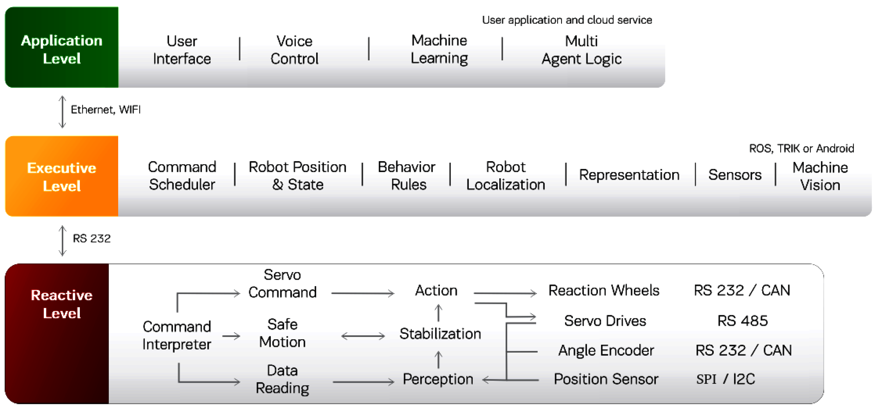
- A reactive level based on a micro-controller that provides control of actuators, data processing from sensors, and control of energy consumption.
- The executive level is implemented on a microprocessor with a full-fledged operating system, implements the basic functionality of the system (orientation in space, video processing, state automaton), taking into account the limitations on computing power and provides the access to the API.
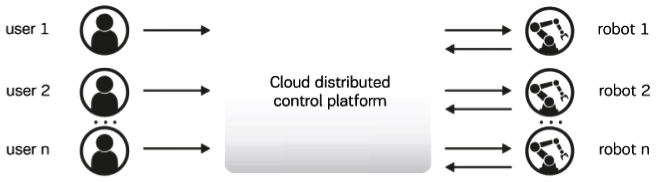
- The application layer represents a distributed cloud application software that solves computationally expensive tasks: physical modeling of motion, elements of artificial intelligence, and collective behavior.
- General technical requirements for the implementation: weight and dimensions, satisfaction of the requirements of industry standards for integration into existing processes, and the application of specialized software packages (ROS, MATLAB, etc.).
- Assessment of the number of connected sensors: based on estimates of the number of sensors necessary to evaluate the load on the network. This assessment determines the choice of network interfaces and standards (EtherCAT, SERCOS III, etc.).
- Specification of the number of drives and non-motorized degrees of freedom. The number of drives determines the workload of the nodes of the computing complex, i.e. the workload of servers and communication channels. For a significant number, it is necessary to divide the computing complex into modules and/or use parallel channels to separate groups of motors.
- Assessment of the need for rapid prototyping: when rapid prototyping is required, it is necessary to use MATLAB/Simulink and systems that support them, such as DSpace DS1104, MicroAutoBox or other external computers for development and debugging.
- Assessment of the criticality of fault tolerance requirements: if one of the main requirements for the architecture is reliability (for example, the braking system of a car or the autopilot system of a copter), you should choose, for example, the CAN Network, which has proven itself as a network with high fault tolerance.
- Determination of computing power for the operation of the system: if large computing power is required, which for one reason or another cannot be placed in the device being developed, then they can be transferred to an external computing module. Calculations can also be divided logically between different nodes of the system.
- Evaluation of the criticality of the noise immunity of the device: the popular solution in the case of the criticality of noise immunity is CAN. However, industrial Internet standards (EtherCAT, SERCOS III and others) also have good noise immunity.
- Evaluation of the limitation on the distance between interacting modules: for example, CAN, with all its advantages in reliability, at distances over 30 m significantly loses in transmission speed.
- Assessment of real-time requirements: depending on the system, a network may be required that guarantees a hard real-time. An estimate of the permissible delay in the robot control loop can be carried out.
- Evaluation of parameters based on the analysis of technical and economic requirements and operating conditions that determine the characteristics of the information and network infrastructure of the general computing complex.
- Distribution of functional tasks for each of the three levels of the computing complex: reactive, executive and application levels.
- The choice of data exchange technologies, microprocessors, based on the obtained estimates of parameters and tasks to be solved.
- Formation of the information and network infrastructure of the complex.
- Application development, configuration of cloud services.
- Implementation.
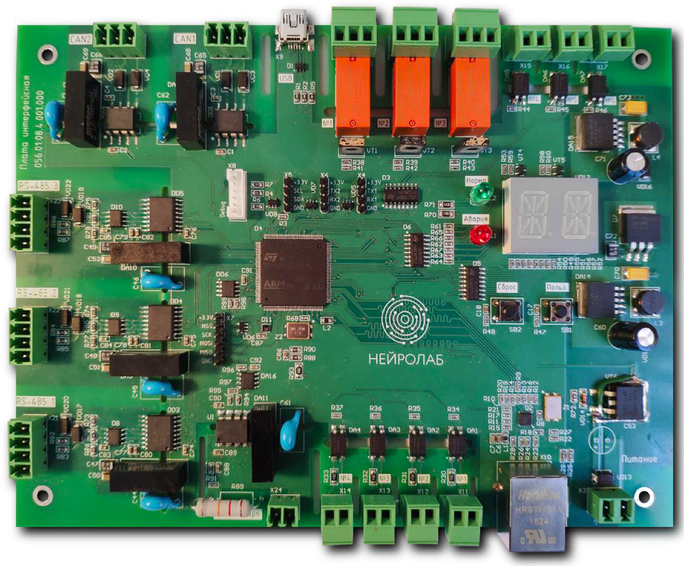
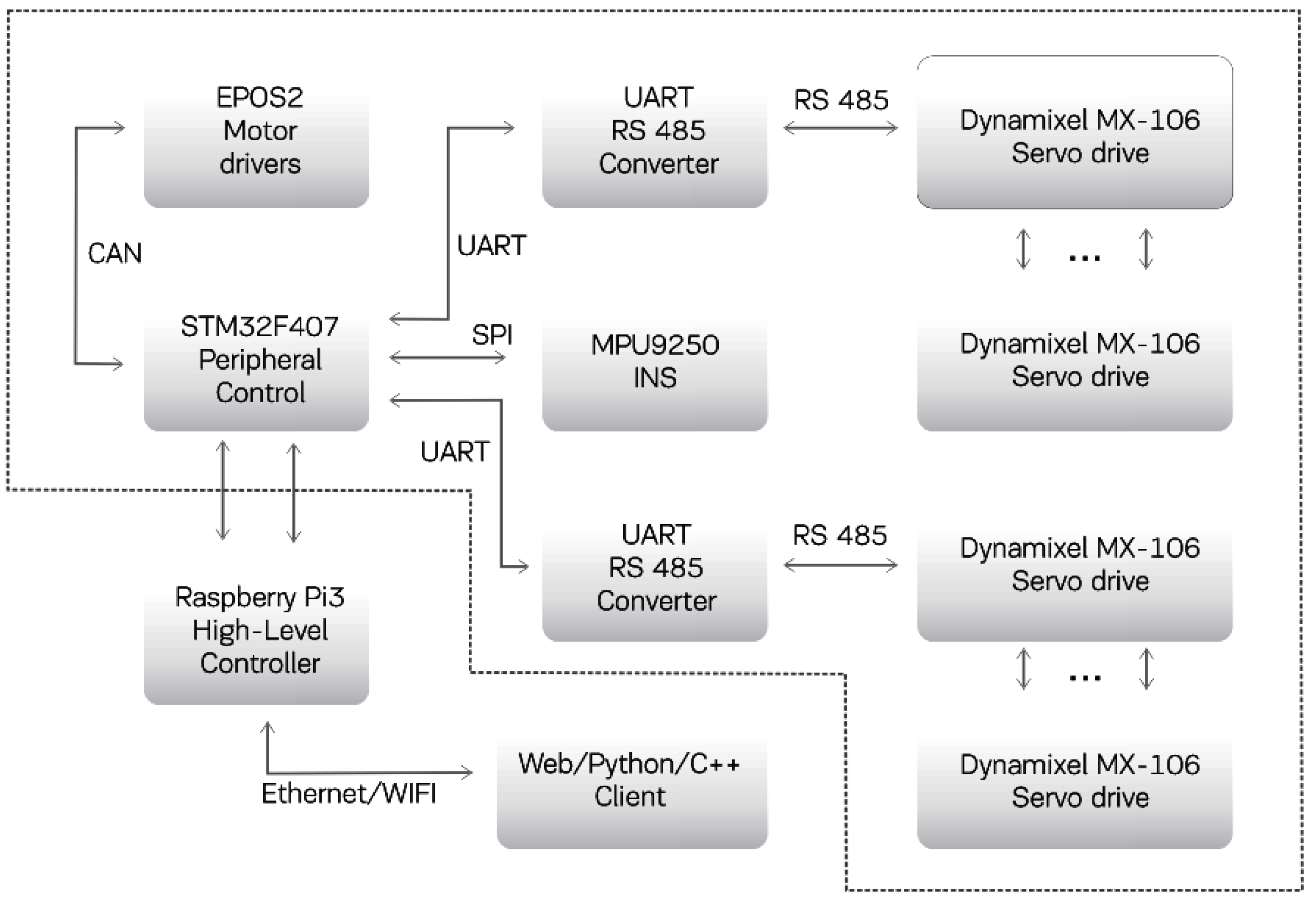
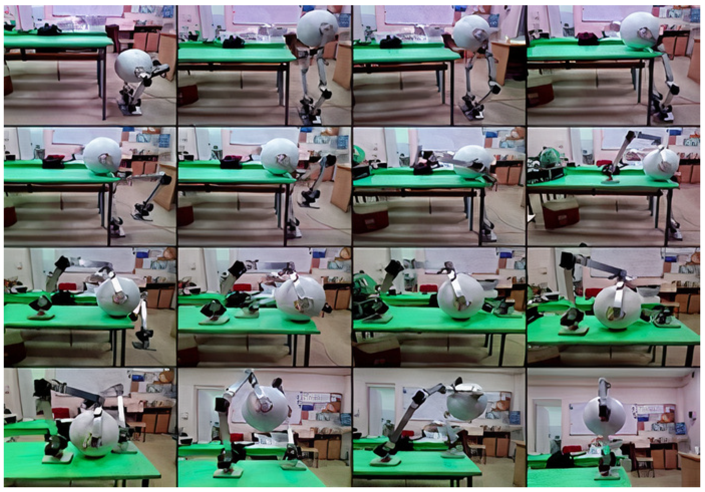
4. Implementation
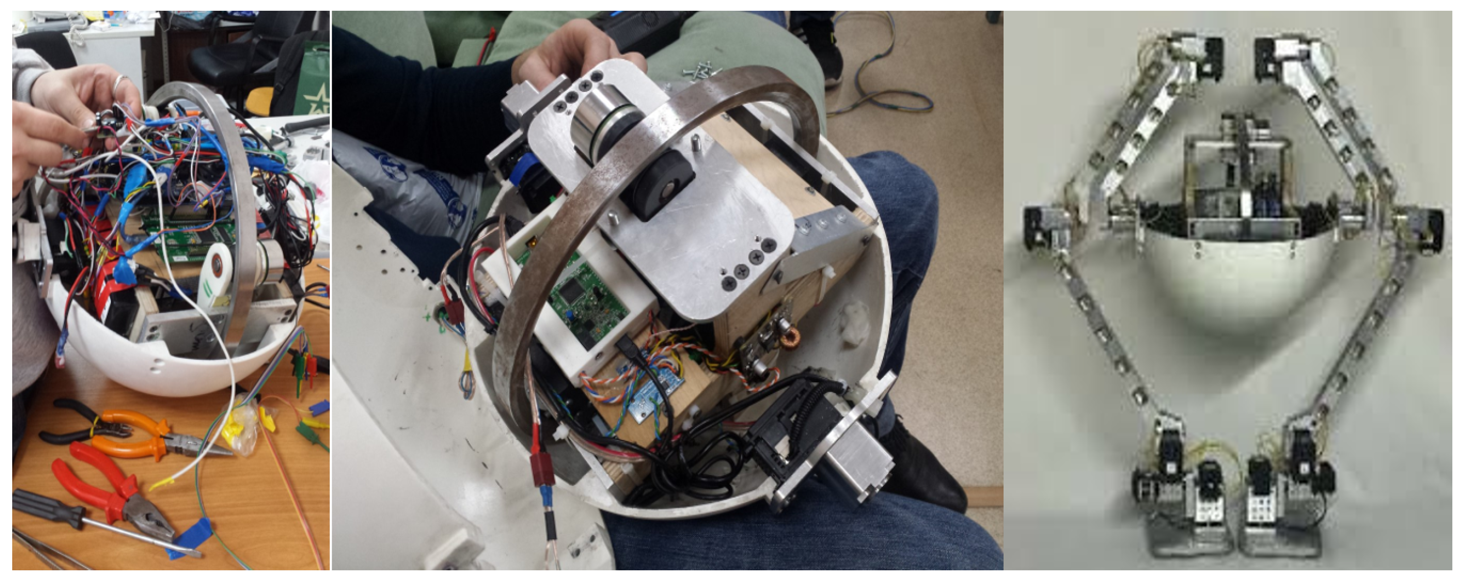
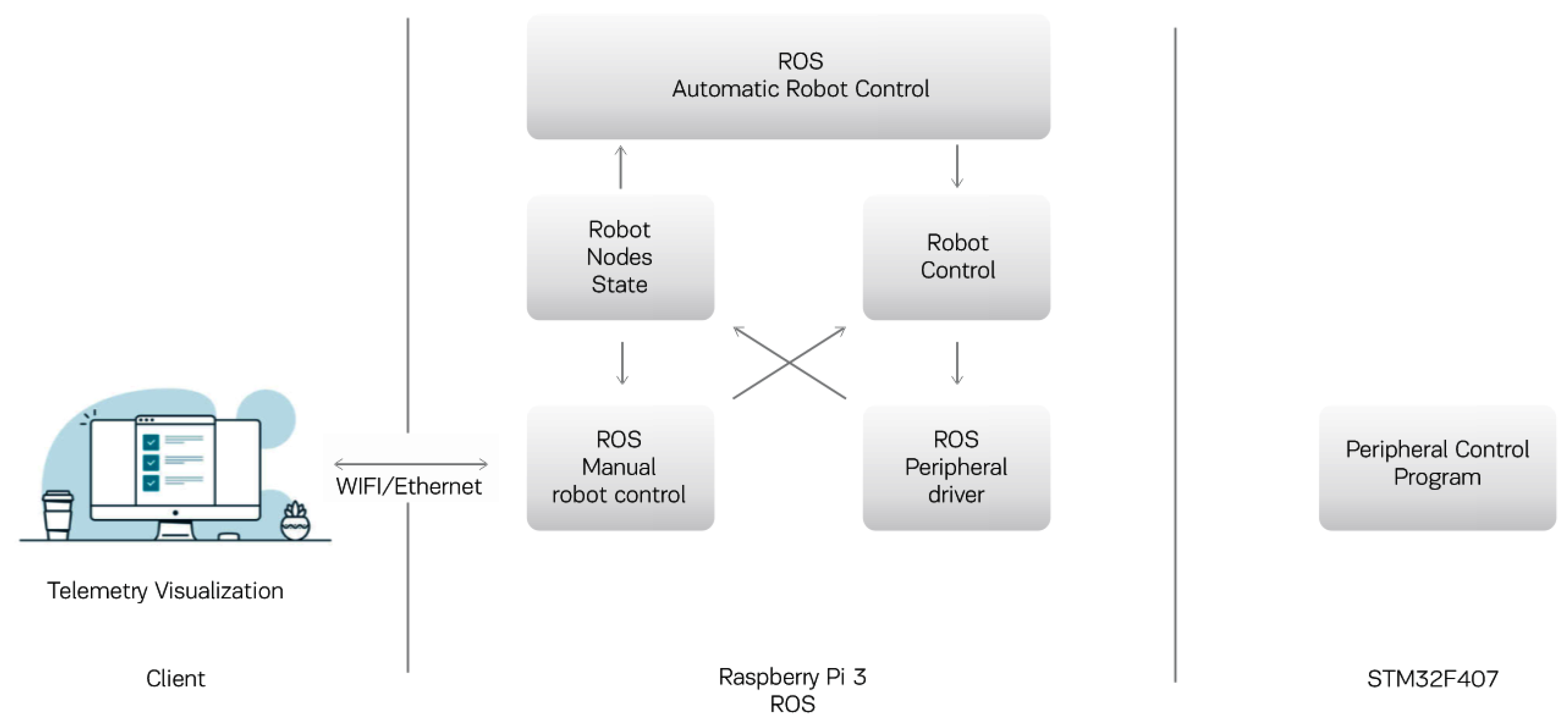
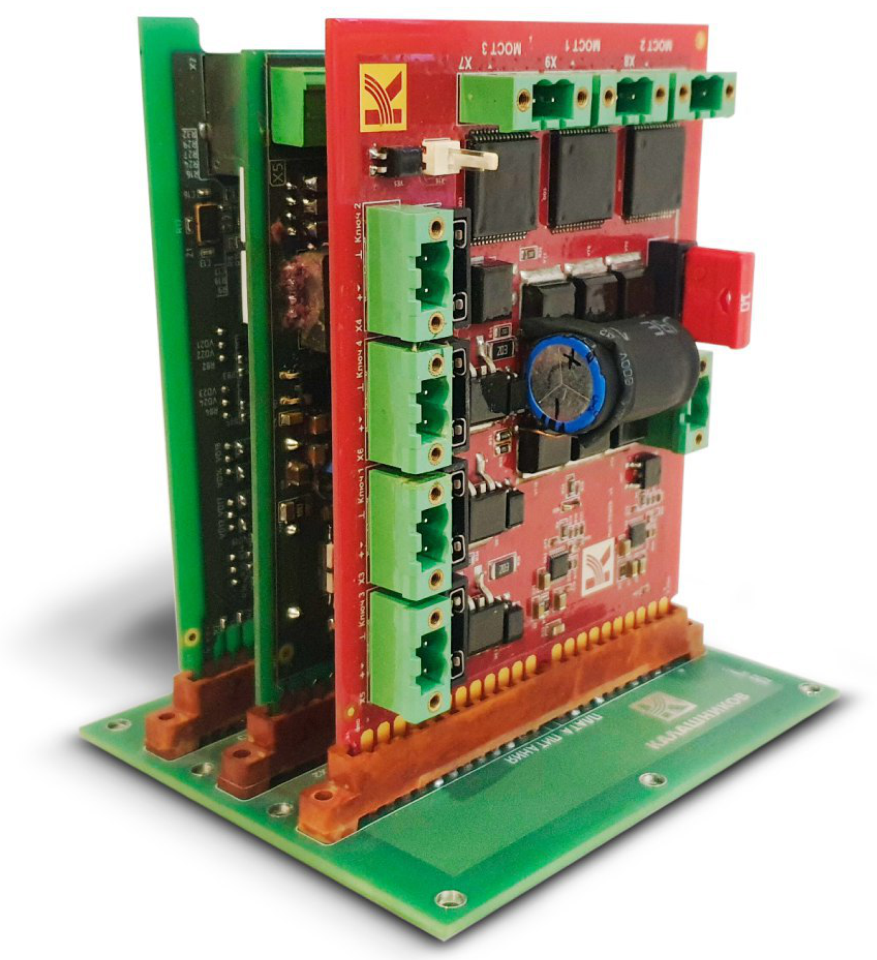
- The reactive level is implemented on the STM32F407 micro controller. The IMU6050-based accelerometers/gyroscopes are polled via the I2C bus and the data is filtered using the Madgwick sensor fusion algorithm. The movement of the flywheels and the calculation of the speed are carried out using Maxon EPOS2 controllers with Maxon EC motors. Dynamixel MX106T actuators for robot legs are controlled via RS485, using a MAX485-based converter.
- The executive level is based on the Raspberry Pi controller with the Robot Operating System installed and is connected to the reactive level via the RS-485 bus. This level implements a simple autonomous behavior, a state machine, provides security and emergency shutdown. Data transfer to the cloud is carried out using Bluetooth, WiFi or Ethernet, if necessary.
- The application layer provides software installed on a personal computer or smartphone, fully or partially located in the cloud. The application layer provides a high-level user interface, supports the API of cloud voice recognition services, collects data from sensors and control commands for machine learning purposes, connects several AnyWalker robots to provide a pattern of collective behavior. It is possible to use algorithmic control support as an information service that allows third-party developers to use the API to solve application problems. An application for the Android platform has also been developed to send motion commands to AnyWalker and display the result.
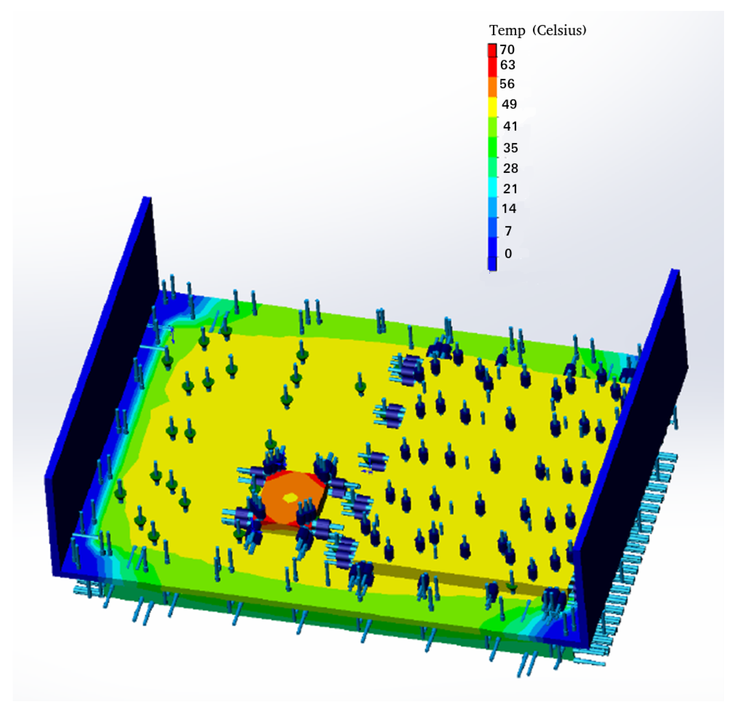
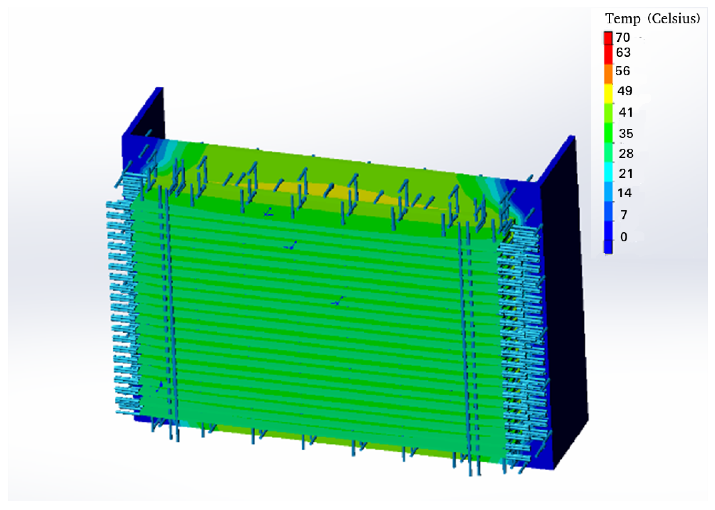
- The value of the medium temperature is 50 °C;
- The value of the peak processor power of 65 Watts;
- The value of the peak power on the converter is 40 Watts;
- The value of the peak power on the input filter is 6 Watts.
5. Discussion
6. Conclusions
Author Contributions
Funding
Institutional Review Board Statement
Informed Consent Statement
Data Availability Statement
Acknowledgments
Conflicts of Interest
Abbreviations
| ROS | Robot Operating System |
| INS | Inertial Navigating System |
| API | Application Programming Interface |
References
- Woo, E.; MacDonald, B.; Trepanier, F. Distributed mobile robot application infrastructure. In Proceedings of the 2003 IEEE/RSJ International Conference on Intelligent Robots and Systems (IROS 2003) (Cat. No. 03CH37453), Las Vegas, NV, USA, 27–31 October 2003; Volume 2, pp. 1475–1480. [Google Scholar] [CrossRef]
- Zhou, B.; Chou, W.; Wu, S. Remote control system of mobile robot based on cloud platform. In Proceedings of the 2017 2nd International Conference on Robotics and Automation Engineering (ICRAE), Shanghai, China, 29–31 December 2017; pp. 94–98. [Google Scholar] [CrossRef]
- Vlasov, A.; Yudin, A. Distributed Control System in Mobile Robot Application: General Approach, Realization and Usage. In Research and Education in Robotics-EUROBOT 2010; Obdržálek, D., Gottscheber, A., Eds.; Springer: Berlin/Heidelberg, Germany, 2011; pp. 180–192. [Google Scholar]
- Chen, Y.; Du, Z.; García-Acosta, M. Robot as a Service in Cloud Computing. In Proceedings of the 2010 Fifth IEEE International Symposium on Service Oriented System Engineering, Nanjing, China, 4–5 June 2010; pp. 151–158. [Google Scholar] [CrossRef]
- Hale, M.T.; Nedić, A.; Egerstedt, M. Cloud-based centralized/decentralized multi-agent optimization with communication delays. In Proceedings of the 2015 54th IEEE Conference on Decision and Control (CDC), Osaka, Japan, 15–18 December 2015; pp. 700–705. [Google Scholar] [CrossRef] [Green Version]
- Hu, G.; Tay, W.P.; Wen, Y. Cloud robotics: Architecture, challenges and applications. IEEE Netw. 2012, 26, 21–28. [Google Scholar] [CrossRef]
- Jones, R.; Haufe, P.; Sells, E.; Iravani, P.; Olliver, V.; Palmer, C.; Bowyer, A. RepRap–the replicating rapid prototyper. Robotica 2011, 29, 177–191. [Google Scholar] [CrossRef] [Green Version]
- Irwin, J.; Pearce, J.M.; Anzalone, G.; Douglas, M.; Oppliger, E. The RepRap 3-D printer revolution in STEM education. In Proceedings of the 121st ASEE Annual Conference & Expostion, Indianapolis, IN, USA, 15–18 June 2014. [Google Scholar]
- Farmbot. Available online: https://repository.najah.edu/handle/20.500.11888/14626 (accessed on 24 October 2021).
- Ma, R.; Dollar, A. Yale openhand project: Optimizing open-source hand designs for ease of fabrication and adoption. IEEE Robot. Autom. Mag. 2017, 24, 32–40. [Google Scholar] [CrossRef]
- Mondada, F.; Bonani, M.; Raemy, X.; Pugh, J.; Cianci, C.; Klaptocz, A.; Magnenat, S.; Zufferey, J.C.; Floreano, D.; Martinoli, A. The e-puck, a robot designed for education in engineering. In Proceedings of the 9th Conference on Autonomous Robot Systems and Competitions, Castelo Branco, Portugal, 7 May 2009; Instituto Politécnico de Castelo Branco (IPCB): Castelo Branco, Portugal, 2009; Volume 1, pp. 59–65. [Google Scholar]
- Winstén, R. Robottiruohonleikkuri. Available online: https://www.theseus.fi/bitstream/handle/10024/136991/Winsten_Ron.pdf?sequence=1&isAllowed=y (accessed on 24 October 2021).
- Graf, N.M.; Behr, A.M.; Daltorio, K.A. Crab-like hexapod feet for amphibious walking in sand and waves. In Conference on Biomimetic and Biohybrid Systems; Springer: Berlin/Heidelberg, Germany, 2019; pp. 158–170. [Google Scholar]
- Berlian, M.H.; Sahputra, T.E.R.; Ardi, B.J.W.; Dzatmika, L.W.; Besari, A.R.A.; Sudibyo, R.W.; Sukaridhoto, S. Design and implementation of smart environment monitoring and analytics in real-time system framework based on internet of underwater things and big data. In Proceedings of the 2016 International Electronics Symposium (IES), Denpasar, Indonesia, 29–30 September 2016; pp. 403–408. [Google Scholar]
- Hahkio, L. Service Robots’ Feasibility in the Hotel Industry: A Case Study of Hotel Presidentti 2020. Available online: https://www.theseus.fi/handle/10024/342703 (accessed on 24 October 2021).
- Mondada, F.; Bonani, M.; Riedo, F.; Briod, M.; Pereyre, L.; Rétornaz, P.; Magnenat, S. Bringing robotics to formal education: The thymio open-source hardware robot. IEEE Robot. Autom. Mag. 2017, 24, 77–85. [Google Scholar] [CrossRef] [Green Version]
- Shalaby, R. Design and Control of an 18 DOF Hexapod Multi-Agent Swarm for Search and Rescue Missions. Ph.D. Thesis, Nile University, Abuja, Nigeria, 2020. [Google Scholar]
- Tarazon, R.L. Chapter 28—Robotics in Micro-manufacturing and Micro-robotics. In Micro and Nano Technologies, Micromanufacturing Engineering and Technology, 2nd ed.; William Andrew Publishing: Burlington, MA, USA, 2015; pp. 661–674. [Google Scholar]
- Jakimovski, B.; Meyer, B.; Maehle, E. Self-reconfiguring hexapod robot OSCAR using organically inspired approaches and innovative robot leg amputation mechanism. In Proceedings of the International Conference on Automation, Robotics and Control Systems, ARCS-09, Orlando, FL, USA, 13–16 July 2009. [Google Scholar]
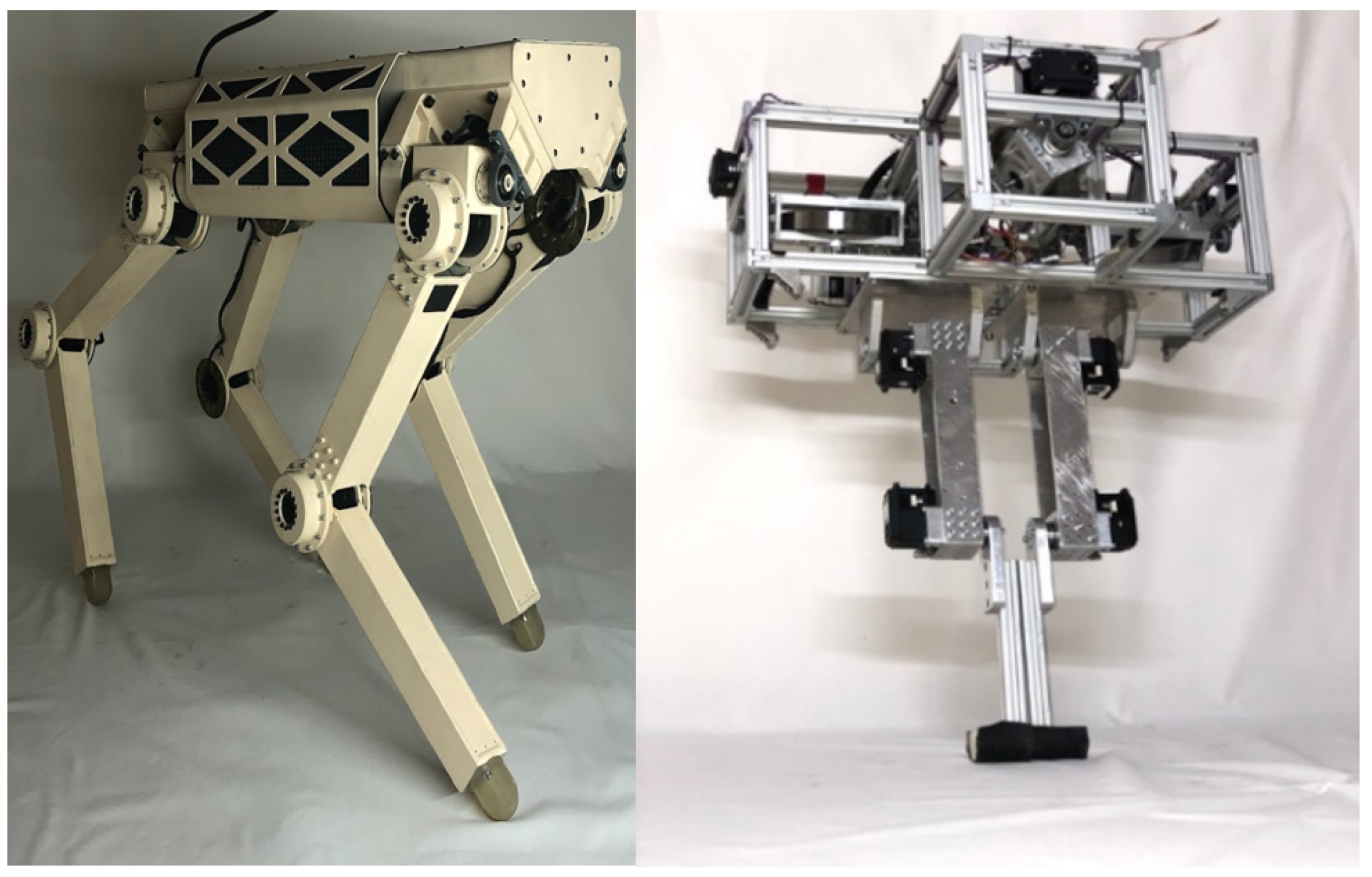
- Ryadchikov, I.; Sechenev, S.; Svidlov, A.; Sinitsa, S.; Buskandze, Z.; Nikulchev, E. AnyWalker: All-terrain robotic chassis. In Proceedings of the ISR 2016: 47st International Symposium on Robotics, Munich, Germany, 21–22 June 2016; pp. 696–701. [Google Scholar]
- Ryadchikov, I.; Sechenev, S.; Nikulchev, E.; Drobotenko, M.; Svidlov, A.; Volkodav, P.; Vishnykov, R. Control and stability evaluation of the bipedal walking robot anywalker. Int. Rev. Autom. Control 2018, 11, 160–165. [Google Scholar] [CrossRef]
- Mendoza-Mendoza, J.A.; Gonzalez-Villela, V.; Sepulveda-Cervantes, G.; Mendez-Martinez, M.; Sossa-Azuela, H. ArduPilot Working Environment. In Advanced Robotic Vehicles Programming; Springer: Berlin/Heidelberg, Germany, 2020; pp. 19–46. [Google Scholar]
- Baidya, S.; Shaikh, Z.; Levorato, M. FlyNetSim: An open source synchronized UAV network simulator based on ns-3 and ardupilot. In Proceedings of the 21st ACM International Conference on Modeling, Analysis and Simulation of Wireless and Mobile Systems, Montreal, QC, Canada, 28 October–2 November 2018; pp. 37–45. [Google Scholar]
- Ebeid, E.; Skriver, M.; Jin, J. A survey on open-source flight control platforms of unmanned aerial vehicle. In Proceedings of the 2017 Euromicro Conference on Digital System Design (DSD), Vienna, Austria, 30 August–1 September 2017; pp. 396–402. [Google Scholar]
- Kritskiy, D.; Alexander, K.; Koba, S.; Druzhinin, E. Increasing the reliability of drones due to the use of quaternions in motion. In Proceedings of the 2018 IEEE 9th International Conference on Dependable Systems, Services and Technologies (DESSERT), Kyiv, Ukraine, 24–27 May 2018; pp. 348–352. [Google Scholar]
- Gati, B. Open source autopilot for academic research-the paparazzi system. In Proceedings of the 2013 American Control Conference, Washington, DC, USA, 17–19 June 2013; pp. 1478–1481. [Google Scholar]
- Lizarraga, M.; Elkaim, G.H.; Curry, R. Slugs uav: A flexible and versatile hardware/software platform for guidance navigation and control research. In Proceedings of the 2013 American Control Conference, Washington, DC, USA, 17–19 June 2013; pp. 674–679. [Google Scholar]
- Goel, A.; Paredes, J.A.; Dadhaniya, H.; Islam, S.A.U.; Salim, A.M.; Ravela, S.; Bernstein, D. Experimental Implementation of an Adaptive Digital Autopilot. In Proceedings of the 2021 American Control Conference (ACC), New Orleans, LA, USA, 25–28 May 2021; pp. 3737–3742. [Google Scholar]
- Zhao, J.; Risi, N.; Monforte, M.; Bartolozzi, C.; Indiveri, G.; Donati, E. Closed-loop spiking control on a neuromorphic processor implemented on the iCub. IEEE J. Emerg. Sel. Top. Circuits Syst. 2020, 10, 546–556. [Google Scholar] [CrossRef]
- Liu, H.; Zeng, L.; Zhou, W.; Zhu, S. A real-time data-driven control system for multi-motor-driven mechanisms. Int. J. Robot. Autom. 2017, 32, 45667. [Google Scholar] [CrossRef]
- Carvajal, D.A.V.; Isaza, J.E.O.; Puerto, J.N.C.; Hemelberg, O.S.N.; Alarcón, M.A.G.; Gómez, M.A.J.; Alfonso, J.A.G. Algoritmos para el procesamiento de imágenes implementados en el Robot Humanoide InMoov. Rev. EIA 2021, 18, 36019. [Google Scholar] [CrossRef]
- Lapeyre, M.; Rouanet, P.; Grizou, J.; Nguyen, S.; Depraetre, F.; Le Falher, A.; Oudeyer, P.Y. Poppy project: Open-source fabrication of 3D printed humanoid robot for science, education and art. Digital Intelligence. 2014, Volume 2014, p. 6. Available online: https://hal.inria.fr/hal-01096338 (accessed on 24 October 2021).
- Wang, Z.; Liu, S.; Zhang, H. Design and Application of Dorabot-hand2 System. In Robotic Grasping and Manipulation Challenge; Springer: Berlin/Heidelberg, Germany, 2016; pp. 84–106. [Google Scholar]
- Schwarz, M.; Pastrana, J.; Allgeuer, P.; Schreiber, M.; Schueller, S.; Missura, M.; Behnke, S. Humanoid teensize open platform nimbro-op. In Robot Soccer World Cup; Springer: Berlin/Heidelberg, Germany, 2013; pp. 568–575. [Google Scholar]
- McLurkin, J.; McMullen, A.; Robbins, N.; Habibi, G.; Becker, A.; Chou, A.; Li, H.; John, M.; Okeke, N.; Rykowski, J.; et al. A robot system design for low-cost multi-robot manipulation. In Proceedings of the 2014 IEEE/RSJ International Conference on Intelligent Robots and Systems, Chicago, IL, USA, 14–18 September 2014; pp. 912–918. [Google Scholar]
- Kapusta, A.S.; Grice, P.M.; Clever, H.M.; Chitalia, Y.; Park, D.; Kemp, C.C. A system for bedside assistance that integrates a robotic bed and a mobile manipulator. PLoS ONE 2019, 14, e0221854. [Google Scholar] [CrossRef]
- Egortsev, M.V.; Diane, S.K.; Kaz, N.D. Algorithmic support of the system of external observation and routing of autonomous mobile robots. Russ. Technol. J. 2021, 9, 15–23. (In Russian) [Google Scholar] [CrossRef]
- Introduction to the Controller Area Network–Texas Instruments. Available online: https://www.ti.com/lit/an/sloa101b/sloa101b.pdf?ts=1638702530387 (accessed on 6 December 2021).
- The RS-232 Standard–Omega Engineering. Available online: https://www.omega.de/temperature/z/rs232standard.html (accessed on 6 December 2021).
- RS-422 and RS-485 Standards Overview and System Configurations–Texas Instruments. Available online: https://www.ti.com/lit/an/slla070d/slla070d.pdf?ts=1638766210683 (accessed on 6 December 2021).
- IEEE 802.3-2018-IEEE Standard for Ethernet. Available online: https://0-standards-ieee-org.brum.beds.ac.uk/standard/802_3-2018.html (accessed on 6 December 2021).
- ARINC 429 Tutorial-AIM online. Available online: https://www.aim-online.com/wp-content/uploads/2019/07/aim-tutorial-oview429-190712-u.pdf (accessed on 6 December 2021).
- Gajamohan, M.; Merz, M.; Thommen, I.; D’Andrea, R. The cubli: A cube that can jump up and balance. In Proceedings of the 2012 IEEE/RSJ International Conference on Intelligent Robots and Systems, Vilamoura-Algarve, Portugal, 7–12 October 2012; pp. 3722–3727. [Google Scholar]
- Glück, T.; Eder, A.; Kugi, A. Swing-up control of a triple pendulum on a cart with experimental validation. Automatica 2013, 49, 801–808. [Google Scholar] [CrossRef]
- Thomas, A. dSPACE DS1103 Control Workstation Tutorial and DC Motor Speed Control; Senior Project Report; Bradley University ECE Department: Peoria, IL, USA, 2009; Volume 478. [Google Scholar]
- Miranda Bermejo, J. Design and Implementation of a Control System for Testing an Experimental Electrical Vehicle. Available online: https://upcommons.upc.edu/handle/2099.1/14638 (accessed on 6 October 2021).
- Nolte, T.; Hansson, H.; Bello, L.L. Automotive communications-past, current and future. In Proceedings of the 2005 IEEE Conference on Emerging Technologies and Factory Automation, Catania, Italy, 19–22 September 2005; Volume 1, p. 8. [Google Scholar]
- Fredriksson, L.B. CAN for critical embedded automotive networks. IEEE Micro 2002, 22, 28–35. [Google Scholar] [CrossRef]
- Leen, G.; Heffernan, D. Expanding automotive electronic systems. Computer 2002, 35, 88–93. [Google Scholar] [CrossRef]
- Kaneko, K.; Harada, K.; Kanehiro, F.; Miyamori, G.; Akachi, K. Humanoid robot HRP-3. In Proceedings of the 2008 IEEE/RSJ International Conference on Intelligent Robots and Systems, Nice, France, 22–26 September 2008; pp. 2471–2478. [Google Scholar]
- Metta, G.; Sandini, G.; Vernon, D.; Natale, L.; Nori, F. The iCub humanoid robot: An open platform for research in embodied cognition. In Proceedings of the 8th Workshop on Performance Metrics for Intelligent Systems, Gaithersburg, MD, USA, 19–21 August 2008; pp. 50–56. [Google Scholar]
- Lim, J.; Bae, H.; Oh, J.; Lee, I.; Shim, I.; Jung, H.; Joe, H.M.; Sim, O.; Jung, T.; Shin, S.; et al. Robot system of DRC-HUBO+ and control strategy of team KAIST in DARPA robotics challenge finals. In The DARPA Robotics Challenge Finals: Humanoid Robots to The Rescue; Springer: Berlin/Heidelberg, Germany, 2018; pp. 27–69. [Google Scholar]
- Tsagarakis, N.G.; Caldwell, D.G.; Negrello, F.; Choi, W.; Baccelliere, L.; Loc, V.G.; Noorden, J.; Muratore, L.; Margan, A.; Cardellino, A.; et al. Walk-man: A high-performance humanoid platform for realistic environments. J. Field Robot. 2017, 34, 1225–1259. [Google Scholar] [CrossRef]
- Stasse, O.; Flayols, T. An overview of humanoid robots technologies. Biomech. Anthr. Syst. 2019, 124, 281–310. [Google Scholar]
- Lohmeier, S. Design and Realization of a Humanoid Robot for Fast and Autonomous Bipedal Locomotion. Ph.D. Thesis, Technische Universität München, Munich, Germany, 2010. [Google Scholar]
- Metta, G.; Fitzpatrick, P.; Natale, L. YARP: Yet another robot platform. Int. J. Adv. Robot. Syst. 2006, 3, 8. [Google Scholar] [CrossRef] [Green Version]
- Baglini, E.; Cannata, G.; Mastrogiovanni, F. Design of an embedded networking infrastructure for whole-body tactile sensing in humanoid robots. In Proceedings of the 2010 10th IEEE-RAS International Conference on Humanoid Robots, Nashville, TN, USA, 6–8 December 2010; pp. 671–676. [Google Scholar]
- Semini, C.; Goldsmith, J.; Rehman, B.U.; Frigerio, M.; Barasuol, V.; Focchi, M.; Caldwell, D.G. Design overview of the hydraulic quadruped robots. In The Fourteenth Scandinavian International Conference on Fluid Power; Tampere University of Technology: Tampere, Finland, 2015; pp. 20–22. [Google Scholar]
- Guo, K.; Li, S.; Huang, D. Real-time quadruped robot control system based on Xenomai. In Proceedings of the 2015 Chinese Automation Congress (CAC), Wuhan, China, 27–29 November 2015; pp. 342–347. [Google Scholar]
- Gui, B.; Wang, H.; Chen, W. Stability analysis for a hexapod robot walking on slopes. In Proceedings of the 2015 IEEE International Conference on Robotics and Biomimetics (ROBIO), Zhuhai, China, 6–9 December 2015; pp. 1888–1893. [Google Scholar]
- Deng, H.; Xin, G.; Zhong, G.; Mistry, M. Object carrying of hexapod robots with integrated mechanism of leg and arm. Robot. Comput. Integr. Manuf. 2018, 54, 145–155. [Google Scholar] [CrossRef] [Green Version]
- Zhao, Y.; Chai, X.; Gao, F.; Qi, C. Obstacle avoidance and motion planning scheme for a hexapod robot Octopus-III. Robot. Auton. Syst. 2018, 103, 199–212. [Google Scholar] [CrossRef]
- Allouche, B.; Dequidt, A.; Vermeiren, L.; Hamon, P. Design and control of a sit-to-stand assistive device via EtherCAT fieldbus. In Proceedings of the 2017 IEEE International Conference on Industrial Technology (ICIT), Toronto, ON, Canada, 22–25 March 2017; pp. 761–766. [Google Scholar]
- Grosu, V.; Guerrero, C.R.; Grosu, S.; Leu, A.; Ristic-Durrant, D.; Vanderborght, B.; Lefeber, D. Real-time physical layer architecture for CORBYS gait rehabilitation robot. In Proceedings of the 2015 IEEE International Conference on Rehabilitation Robotics (ICORR), Singapore, 11–14 August 2015; pp. 606–611. [Google Scholar]
- Rebelo, J.; Sednaoui, T.; Den Exter, E.B.; Krueger, T.; Schiele, A. Bilateral robot teleoperation: A wearable arm exoskeleton featuring an intuitive user interface. IEEE Robot. Autom. Mag. 2014, 21, 62–69. [Google Scholar] [CrossRef]
- Ando, N.; Suehiro, T.; Kitagaki, K.; Kotoku, T.; Yoon, W.K. RT-middleware: Distributed component middleware for RT (robot technology). In Proceedings of the 2005 IEEE/RSJ International Conference on Intelligent Robots and Systems, Edmonton, AB, Canada, 2–6 August 2005; pp. 3933–3938. [Google Scholar]
- Bangura, M.; Mahony, R. Real-time model predictive control for quadrotors. IFAC Proc. Vol. 2014, 47, 11773–11780. [Google Scholar] [CrossRef]
- Turpin, M.; Michael, N.; Kumar, V. Trajectory design and control for aggressive formation flight with quadrotors. Auton. Robot. 2012, 33, 143–156. [Google Scholar] [CrossRef]
- Wilamowski, B.M.; Irwin, J.D. Industrial Communication Systems; CRC Press: Boca Raton, FL, USA, 2018. [Google Scholar]
- Pluzhnik, E.; Lukyanchikov, O.; Nikulchev, E.; Biryukov, D. Developing middleware for hybrid cloud computing architectures. In Proceedings of the 2015 International Conference “Stability and Control Processes” in Memory of V.I. Zubov (SCP), St. Petersburg, Russia, 5–9 October 2015; pp. 586–588. [Google Scholar] [CrossRef]
- Deryugina, O.; Nikulchev, E.; Ryadchikov, I.; Sechenev, S.; Shmalko, E. Analysis of the AnyWalker Software Architecture Using the UML Refactoring Tool. Procedia Comput. Sci. 2019, 150, 743–750. [Google Scholar] [CrossRef]
- Ryadchikov, I.; Sechenev, S.; Sinitsa, S.; Svidlov, A.; Volkodav, P.; Feshin, A.; Alotaki, A.; Bolshakov, A.; Drobotenko, M.; Nikulchev, E. Design and control of self-stabilizing angular robotics anywalker. Int. J. Adv. Comput. Sci. Appl. 2017, 8, 29. [Google Scholar] [CrossRef] [Green Version]


| Name | CAN | RS-232 | RS-422 | RS-485 | ARINC | Ethernet |
|---|---|---|---|---|---|---|
| Bit rate, Mbit/s | 1 | 1 | 10 | 10 | 0.1 | 1000 |
| Distance, m | 40 | 10 | 10 | 10 | - | 100 |
| Noise Immunity | yes | no | yes | yes | yes | yes |
| Correction of Errors | yes | no | no | no | yes | yes |
| Bus Arbitration | yes | no | no | no | no | yes |
| Reservation | no | no | no | no | no | no |
| Number of Devices | 32 | 2 | 11 | 32 | 21 | unlimited |
Publisher’s Note: MDPI stays neutral with regard to jurisdictional claims in published maps and institutional affiliations. |
© 2021 by the authors. Licensee MDPI, Basel, Switzerland. This article is an open access article distributed under the terms and conditions of the Creative Commons Attribution (CC BY) license (https://creativecommons.org/licenses/by/4.0/).
Share and Cite
Sechenev, S.; Ryadchikov, I.; Gusev, A.; Lampezhev, A.; Nikulchev, E. Development of a Design Methodology for Cloud Distributed Control Systems of Mobile Robots. J. Sens. Actuator Netw. 2022, 11, 1. https://0-doi-org.brum.beds.ac.uk/10.3390/jsan11010001
Sechenev S, Ryadchikov I, Gusev A, Lampezhev A, Nikulchev E. Development of a Design Methodology for Cloud Distributed Control Systems of Mobile Robots. Journal of Sensor and Actuator Networks. 2022; 11(1):1. https://0-doi-org.brum.beds.ac.uk/10.3390/jsan11010001
Chicago/Turabian StyleSechenev, Semyon, Igor Ryadchikov, Alexander Gusev, Abas Lampezhev, and Evgeny Nikulchev. 2022. "Development of a Design Methodology for Cloud Distributed Control Systems of Mobile Robots" Journal of Sensor and Actuator Networks 11, no. 1: 1. https://0-doi-org.brum.beds.ac.uk/10.3390/jsan11010001