Article

High Resolution-Based Coherent Photonic Radar Sensor for Multiple Target Detections

1
Wireless Communication Ecosystem Research Unit, Department of Electrical Engineering, Chulalongkorn University, Bangkok 10330, Thailand
2
Department of Electronics Technology, Guru Nanak Dev University, Amritsar 143005, India
3
Quanzhou Institute of Equipment and Manufacturing, Chinese Academy of Sciences, Jinjiang 362215, China
4
Software Engineering Institute (SEI), East China Normal University, Shanghai 200050, China
*
Authors to whom correspondence should be addressed.
J. Sens. Actuator Netw. 2022, 11(3), 49; https://0-doi-org.brum.beds.ac.uk/10.3390/jsan11030049
Submission received: 9 August 2022 / Revised: 20 August 2022 / Accepted: 22 August 2022 / Published: 28 August 2022
(This article belongs to the Special Issue Advances in Intelligent Transportation Systems (ITS))

Abstract

:
The last decade witnessed remarkable growth in the number of global road accidents. To minimize road accidents, transportation systems need to become more intelligent. Multiple detection of target vehicles under adverse weather conditions is one of the primary challenges of autonomous vehicles. Photonic radar sensors may become the promising technology to detect multiple targets to realize autonomous vehicles. In this work, high-speed photonic radar is designed to detect multiple targets by incorporating a cost-effective wavelength division multiplexing (WDM) scheme. Numerical simulations of the proposed WDM-based photonic radar is demonstrated in terms of received power and signal to noise (SNR) ratio. The performance of the proposed photonic radar is also investigated under diverse weather conditions, particularly low, medium, and thick fog. The proposed photonic radar demonstrated a significant range resolution of 7 cm when the target was placed at 80 m distance from the photonic radar sensor-equipped vehicle. In addition to this, traditional microwave radar is demonstrated to prove the effectiveness of the proposed photonic radar.

1. Introduction

Road accidents are one of the leading causes of death, taking around 1.2 million lives each year worldwide [1]. The increasing number of road accidents has put tremendous pressure on transportation systems to make vehicles intelligent. It is estimated that 90% of road fatalities could be reduced with the help of an intelligent transport system (ITS) [2]. In 2019, the ITS market shared a cap of 26.68 billion USD which is expected to reach a 5.8 percent growth rate by the end of 2027 [3]. The main goal of ITS is not only to ease traveling for people but also to reduce traffic fatalities. Autonomous vehicles are considered to be a key element for emerging intelligent transportation systems. It is estimated that 90% of transport fatalities can be reduced with the help of autonomous cars. These intelligent cars can provide numerous advantages; for example, they can assist one with parking, detect lanes, and monitoring blind spots, and they can detect multiple targets using various sensors such as radars and cameras. Photonic radar can play a vital role in extracting information about the traffic environment such as speed, altitude, distance, and image from various targets. Photonic radar modulates radio frequency into optical carrier and then transmits through free space link toward the target. The required information can be extracted by processing the target-originated reflected echoes.
Photonic radar enables the autonomous vehicle to avoid collision with other traffic environments, such as pedestrians, trees, and buildings, as well as other vehicles on the road. However, radio frequency-driven microwave radars are high cost, low bandwidth, poor resolutions, and low speed, which make these radars a misfit for autonomous vehicles. Photonic radar provides low power supply requirements, which is one of the significant factors making it a preferred choice for autonomous vehicles [4,5,6]. In 2018 [6], authors reported higher power requirement of traditional microwave radars compared to that of photonic radars. The key features of a photonic radar, such as high-speed resolution with precision, make it an attractive application for autonomous vehicles as compared to traditional microwave-based radars [7,8]. Frequency band selection in radars plays a vital role in order to achieve long-range detections. The X-band (8–12 GHz) offers narrow beams for tracking targets whereas S-band offers robust immunity against atmospheric turbulences [9]. Moreover, photonic radars industries have started to operate in the high-frequency band (74–77 GHz) to achieve high-speed resolutions. Although the performance of photonic radars usually suffers from atmospheric propagation characteristics, the radar signal highly suffers from attenuation when subjected to different atmospheric commotions including fog, rain, snow, and dust. The range resolution ability of photonic radars is affected when the radar signal propagates through atmospheric turbulences due to scattering and absorption through different atmospheric gases and other atmospheric elements [8,10]. Thus, it is highly important to consider atmospheric turbulences while designing photonic radars. In [11,12], the authors investigated the effect of dust, smoke, and other random atmospheric variations on the performance of autonomous vehicles. In 2016 [13], researchers demonstrated a synthetic aperture radar by adopting multibeam technique and wavelength division multiplexing (WDM) to achieve high resolutions. In another work [14], researchers generated and detected S- and X-band signals by employing linear frequency modulated continuous wave (LFMCW)-based photonic radar. In 2017 [15], researchers demonstrated photonic synthetic aperture radar with 600 MHz bandwidth and Ku band. The authors used frequency doubling technique to transmit a linear frequency modulated (LFM) signal and photonic stretch processing scheme to receive the reflected signal. In another work [14], researchers proposed a photonics-based LFMCW radar using microwave photonic in-phase and quadrature (I/Q) mixer. The proposed LFMCW radar can perform over wide-frequency range as the used I/Q mixer has large bandwidth and high I/Q balance features. In 2018 [16], researchers demonstrated a photonic time-stretch coherent radar (PTS-CR) system by employing Erbium Doped Fiber Amplifier (EDFA). The results reported that the Signal to Noise Ratio (SNR) can be improved if the input power of EDFA is controlled. The proposed PTS-CR offers 1.48 cm of range resolution and can operate over W Band with 12 GHz ultrabroad bandwidth. In 2019 [17], researchers proposed dual-band LFM continuous radar by employing photonic deramp receiver. The proposed photonic radar can operate over C and Ku bands with 850 MHz and 3600 MHz bandwidth, respectively. In another work [18], researchers proposed the method of generating LFM signal using optical frequency comb (OFC) generated from dual-drive Mech Zhender modulator (DDMZM). The proposed photonic radar can generate the LFM signals in different bands and transmit over same optical path which enables natural coherence at minimum costs. FMCW-based photonic radars have garnered attention and many key works have been introduced recently [19,20,21]. In 2020 [22], researchers demonstrated a photonic radar that can detect the movement of drones at the range of 2.7 km. The proposed radar operates in the X-band and can provide real-time image of drones from the distance of 1.1 km. In 2021 [20], researchers proposed microwave photonic radar to detect the distance and velocity of target. The proposed photonic radar can measure the velocity and distance of target with maximum relative error of 2.6% and 0.21%, respectively. Recently, in 2022 [23], researchers demonstrated dual chirp-based microwave photonics radar for measurement of velocity and speed of targets. The proposed photonic radar can detect the stationary target and moving target with the maximum distance measurement error of 1.560 cm and 1.2 cm, respectively. The current work aims at designing LFMCW-based photonic radar to detect multiple targets by employing the wavelength division multiplexing (WDM) scheme. The proposed photonic radar is able to detect four different targets at the same time. The work discusses principles of the proposed photonic radar in Section 2, its core design in Section 3, results in Section 4, and conclusions in Section 5.

2. Major Contribution and Principle of Photonic Radar

Bandwidth plays a vital role in the functioning of range resolution of a radar. With transmitted pulses having more bandwidth, radar can distinguish multiple targets with closer distances. This is the reason radar manufacturers prefer 77 GHz band to 24 GHz band [24]. At 77 GHz band, it is possible to achieve a bandwidth of 4 GHz as compared to 24 GHz band which provides only 200 MHz bandwidth. The bandwidth provided by the 77–81 GHz band can offer almost 20 times better range resolution as compared to the 24 GHz band. Moreover, it offers velocity resolution three times better than that of 24 GHz band [25]. The proposed photonic radar is based on the Doppler Effect principle in which transmission of optical modulated transmitted pulse occurs over free space path to the target. It then captures and processes reflected echoes from the target to attain information such as distance and speed. The direct transmission of millimeter waves, as in the case of radar, involves harmonic distortions which can be reduced while transmitting over optical carrier by controlling the bias voltage of DMZM. Moreover, the beam divergence of radar is typically wide, which results in difficulty to differentiate multiple targets whereas beam divergence of laser-driven photonic radar is small as the laser features narrow linewidth. This makes photonic radar an excellent choice for autonomous cars [26]. The range frequency fr of photonic radar can mathematically be derived from the following equation [27,28]:
f r = 2 × B × R T S × c
where B refers to the bandwidth of transmitted pulse, R the distance, TS the time sweep, and c refers to the speed of light. To detect multiple targets (four targets), WDM scheme is adopted. It aims at transmitting four different channels with narrow spacing of 0.1 nm, each one carrying LFM signal modulated over optical carrier, over free space channel toward the target. Moreover, it investigates the performance of the proposed photonic radar under different atmospheric turbulences, such as fog and rainfall. Furthermore, it considers two different scenarios for establishing and comparing microwave radar with photonic radar.

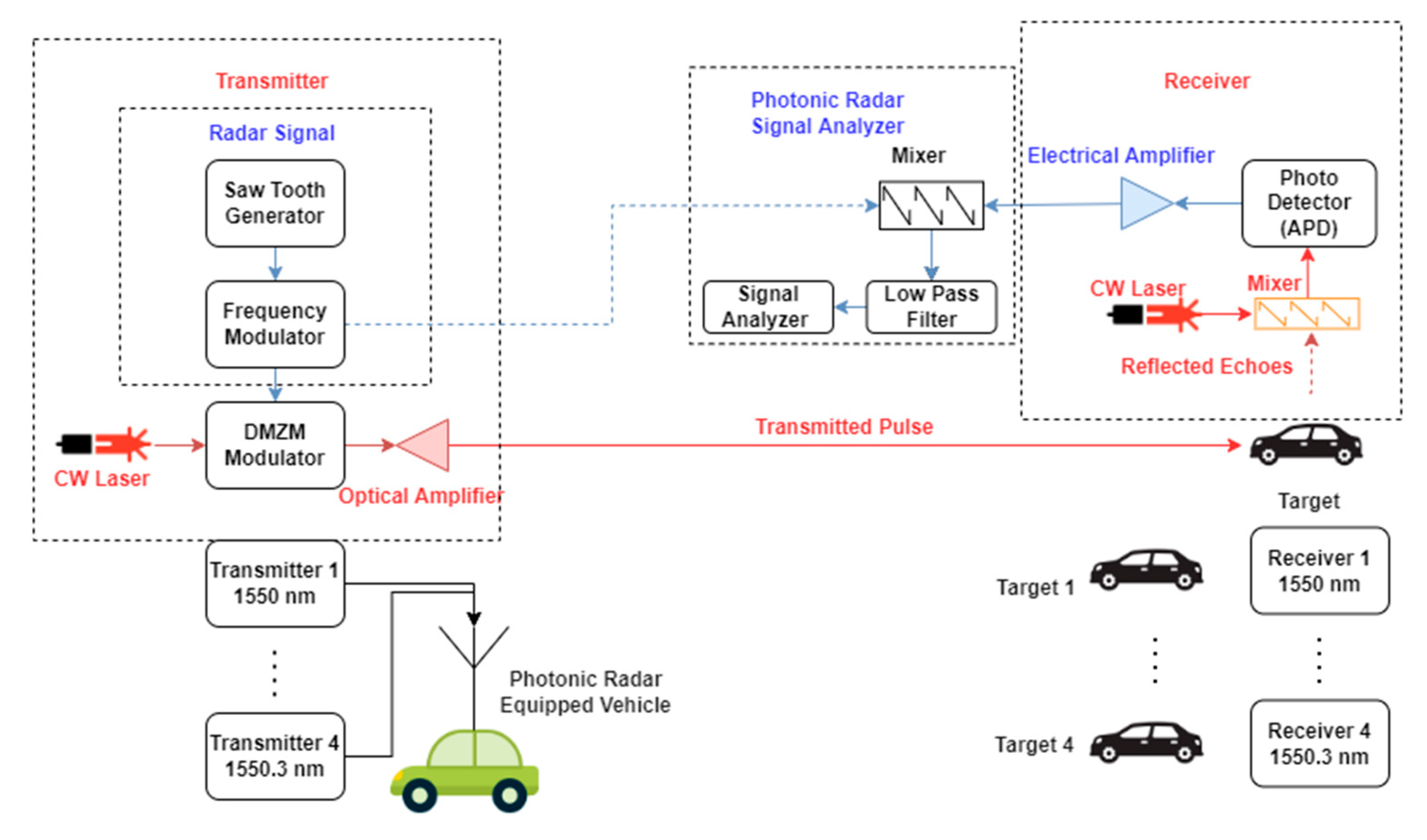
3. Proposed Photonic Radar Modeling

Figure 1 shows the schematic diagram of the proposed photonic radar for multiple target detection.
Four independent photonic radar transmitters operating at 1550 nm, 1550.1 nm, 1550.2 nm, and 1550.3 nm are combined using WDM technique as shown in Figure 1. These transmitters use narrow channel spacing of 0.1 nm to ensure the least usage of optical bandwidth. Each transmitter comprises of three main parts: generation of LFM radar signal, photonic radar receiver and photonic radar signal analyzer. Now in each photonic radar transmitter, a sawtooth signal is generated and modulated over low-frequency radio signal of 77 GHz and bandwidth of 600 MHz using frequency modulator (FM). A splitter is used to split the output of FM modulator into two parts: signal modulation over optical carrier using DMZM and RF signal with the target-driven reflected echoes for detection. DMZM is derived from continuous wavelength laser with the power of 1 mW and linewidth of 100 KHz. With such low input power, the requirement of low power to autonomous vehicles is also fulfilled due to limited power supply from the batteries. Additionally, such a narrow linewidth of laser ensures the distinguishing of multiple targets. Now to ensure coherent detection, DMZM operates in null transmission stage. The bias voltage of +1 V and −1 V is applied to the two inputs of DMZM modulator whereas switching bias and RF voltage is fixed at 4 V. The mathematical equation of the output of modulated signal (E(t)) at the DMZM modulator is given below [28,29]:
E ( t ) = E i n ( t ) 10 I L / 20 × ( ( γ × e ( j π v 2 ( t ) / V π R F + j π v b i a s 2 / V π D C ) + ( ( 1 γ ) × e ( j π v 1 ( t ) / V π R F + j π v b i a s 1 / V π D C ) )
In the above equation, Ein(t) refers to input (optical) signal, IL represents insertion loss, v1 and v2 the input bias voltages applied to lower and upper arms of MZM, VπRF represents switching modulation voltage, VπDC represents switching bias voltage, γ represents symmetrical power splitting ratio of Y-branch waveguides, V b i a s 1 bias voltage 1 and V b i a s 2 bias voltage 2. Optical amplifier is used for amplifying the DMZM output with the gain of 13 dB. This amplified optical signal is transmitted toward the target through free space channel. In this work, the Gamma fading channel is considered to be a free space channel and designed in the MATLABTM program. The free space model is expressed mathematically as [30]:
P R e c e i v e d = P T r a n s m i t t e d × d R 2 ( d T + θ R ) 2 10 α R 10
where dR refers to the receiver aperture diameter, dT the transmitter aperture diameter, θ a beam divergence, R the range and α refers to atmospheric turbulences. Rainfall and fog are considered to be the primary atmospheric commotions for autonomous vehicles which hamper the performance of photonic radars specifically in the millimeter band.
Marshall Palmer distribution [31] can be used to compute power law variables. The values of attenuation are measured as 2 dB, 4.6 dB, and 6.9 dB for modeling light, heavy, and strong rainfall, respectively. Similarly, attenuation under foggy weather is calculated using the Mie scattering empirical model, which is mathematically expressed as [32]:
( λ ) = 3.91 V ( λ 550 ) ρ  
where λ represents laser operating wavelength, V as visibility (kms) and ρ the scattering size distribution coefficient. As per International Telecommunication Union (ITU), the visibility for heavy fog, moderate fog, and low fog conditions is considered to be 200 m, 500 m, and 750 m, respectively. Thus, after using the values of Visibility into Equation (5), attenuation values are computed as 70 dB/km for heavy fog, 28.9 dB/km for moderate fog, and 18.3 dB/km for light fog. The reflected echo from the target is mixed at the receiver side with the output of the same laser which is used at the transmitter side for coherent detection as shown in Figure 1. Then, the output of the mixer is received by the set of two balanced photodetectors (PIN). The received power Pr of the reflected echo from the target is given by:
P r   = { P t   ρ t   D 2   τ o p t τ a t m 2 4 R 2                                           f o r   e x t e n d e d   t a r g e t P t   ρ t   A t D 2   τ o p t τ a t m 2 4 R 2 A i l l                                                         f o r   a n y   t a r g e t
where D refers to the receiver aperture diameter, ρt a target reflectivity, At target area, τopt the optical transmission loss, τatm the atmospheric loss, Aill illuminated target area, and R refers to the target range. The incident optical electrical field E p d 1 at photodetector 1 is represented as [28]:
E p d 1 = 1 2 [ E l o ( t ) + j E r e f ( t ) ]
Similarly, incident optical electrical field E p d 2 at photodetector 2 is represented as:
E p d 2 = 1 2 [ E l o ( t ) + E r e f ( t ) ]
In the above Equations (8) and (9), E l o ( t ) is mathematically represented as:
E l o ( t ) = P l o e j ( ω o ( t ) + θ o ( t ) )
where θ o ( t ) refers to the optical phase variation generated from CW laser with P l o as its optical power and E r e f ( t ) the incident optical field in the reflected echoes from the target which is expressed as:
E r e f ( t ) = P r   cos [   2 π f s t a r t ( t τ ) + π B T m   ( t τ ) 2 ] . e ( j ( ω o ω d ) t + θ o ( t ) )  
where τ refers to propagation delay as in τ = 2 × R/c (R is the range and c the speed of light), B the modulation bandwidth and T m refers to time duration. Now, to obtain the beat signal (( S b ( t ) ), the output of the balanced photodetectors is combined with the signal of LFM generated at the transmitter side. Its output is then transmitted through a low pass filter which regulates range frequency ( f r ) and doppler frequency ( f d ). The beat signal S b ( t ) is expressed below:
S b ( t ) = × A l o × P l o × P r   cos [   2 π f s t a r t τ + π β T m   ( τ ) 2 + 2 π f r ( t ) ] sin [ ω d ( t ) + ( θ o ( t ) θ l o ( t ) ) ]
where ( f r ) refers to range frequency (Equation (1)) and A l o the LFM amplitude. Table 1 shows the other modeling parameters for designing the proposed photonic radar.

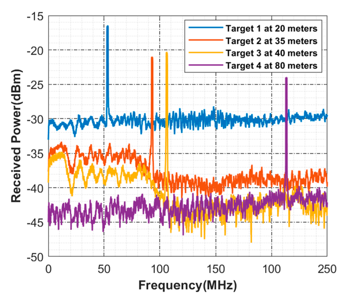
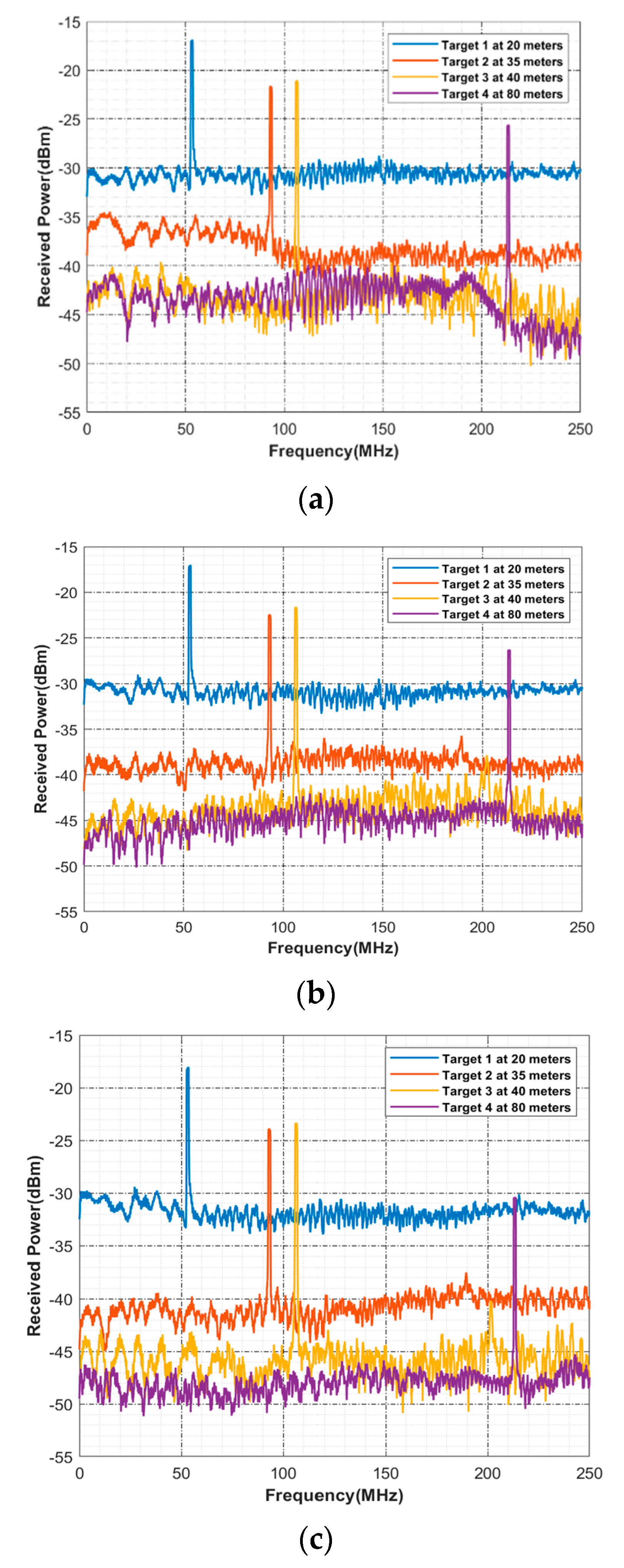
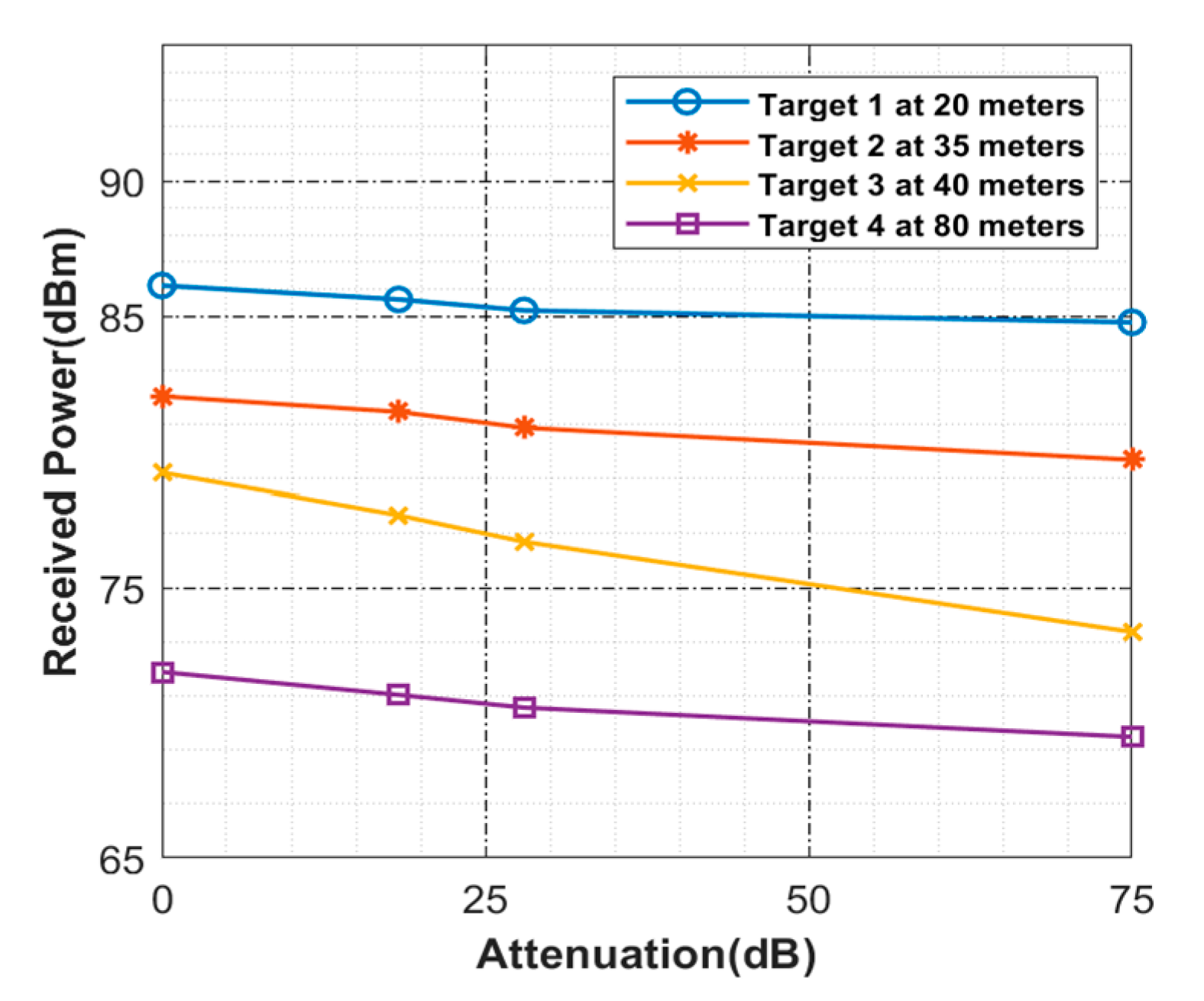
4. Results and Discussion

The numerical simulations obtained from the modeling of the proposed photonic radar for multiple targets are presented and discussed in this section. Figure 2 represents the detection of four targets under the influence of clear weather conditions. Now to consider multiple targets at different distance values, Target 1 is assumed to be at the distance of 20 m whereas Target 2 is assumed at 35 m, Target 3 is assumed at 40 m, and Target 4 is assumed at 80 m. In these cases, Target 1 peak is detected at 53.20 MHz with −16.50 dBm threshold power.
For Target 2, the peak is detected at 92.90 MHz with 21 dBm threshold power whereas for Target 3, it is detected at 106 MHz with 20 dBm threshold power and 213 MHz with 23 dBm threshold power for Target 4. This also satisfies Equation (1). Hence, the reported detection peak from the numerical simulation meets with the criteria of mathematical derivation. When the atmospheric conditions relatively change to fog, the threshold power of the detected peaks reduces accordingly. Figure 3 shows the computed spectrums for the four targets under the atmospheric impact of low, medium, and thick fog conditions.
As shown in Figure 3a, under the impact of low fog, Target 1 is detected with the required threshold power of 16.56 dBm, Target 2 with 21.65 dBm, Target 3 with 21 dBm, and Target 4 with 25.74 dBm. Similarly in Figure 3b, under the impact of medium fog, Target 1 is detected with the threshold power of 17.21 dBm, Target 2 with 22.35 dBm, Target 3 with 21.62 dBm, and Target 4 with 26.31 dBm. In the case of thick fog as shown in Figure 3c, Target 1 is detected with the threshold power of 18.02 dBm, Target 2 with 24.21 dBm, Target 3 with 23.37 dBm, and Target 4 with 30.43 dBm. It shows successful detection of all the targets under the impact of different atmospheric conditions.
Figure 4 shows the computed Signal to Noise ratio (SNR) for all the targets under various atmospheric attenuation influences. The maximum attenuation value is considered to be 75 dB which is in the case of thick fog. Here, it can show that all the targets are detected successfully with high SNR under 75 dB attenuation.
Another key feature of FMCW-based photonic radar systems is the ability to distinguish between closely spaced targets, also known as range resolution, to avoid any mishaps. Range resolution Lres can be mathematically described as [33]:
L r e s = c 2 B
Theoretically, for the bandwidth 4 GHz, range resolution should be 3.75 cm as per Equation (11). Figure 5 depicts the range resolution of the proposed system at 80 m and 60 m from photonic radar-equipped vehicle. Target 1 is placed at 80 m and Target 2 is separated by 7 cm from Target 1 and placed at 79.03 m. Likewise, Target 3 is placed at 60 m and Target 4 is placed at 59.03 m, separated by 7 cm from Target 3. The observed peaks satisfy Equation (1) which shows the successful detection of multiple targets that are separated by 7 cm from one another.
The effectiveness of the proposed photonic radar sensor is established by designing conventional FMCW radar which is the extension of this work. Figure 6 shows the two scenarios of a car which has a mounted conventional FMCW radar. The speed of FMCW radar-equipped car is assumed to be 50 km/h (13.88 m/s). The distance between the FMCW radar-equipped car and target car is considered to be 40 m. In the first scenario, the target car is assumed to be moving toward the radar-equipped car at a speed of 50 km/h (same as with the radar-equipped car). In this case, the relative velocity is calculated as 0 m/s. In the second scenario, the target car is assumed to be moving at a speed of 5.55 m/s toward the radar-equipped car, hence the relative velocity is calculated as 8.33 m/s.
The computed radar pattern response is presented in Figure 7. In the case of Scenario 1, since both the radar-equipped vehicle and target vehicle are moving at the same speed, the velocity of the target vehicle is detected as 0 m/s at the distance of 40 m. The threshold power of the detected target is computed as 60 dB. In Scenario 2, the target vehicle is moving at the speed of 5.55 m/s with its relative velocity of 8.33 m/s at the distance of 40 m. The threshold power in this case is measured as 40 dB. This indicates that the proposed photonic radar sensor has higher threshold power of detected targets with longer distances as compared to microwave radars.

5. Conclusions

In this work, a photonic radar sensor is designed for intelligent transport vehicles which can detect four different targets by incorporating the WDM scheme. The modeling of the proposed photonic radar sensor is carried out in the MATLAB software. A Gamma model is used to design the free space optical path. Numerical simulations demonstrated successful detection of four targets with the threshold power values of −16.50 dBm, −21 dBm, −20 dBm, and −23 dBm, respectively, under clear weather conditions. Moreover, the proposed photonic radar has reported a significant range resolution of 7 cm when the targets are placed at a distance of 80 m from the photonic radar sensor-equipped vehicle. Furthermore, this work investigated the performance of the proposed photonic radar sensor under the influence of low fog, medium fog, and thick fog conditions. Reported results show successful detection of all targets under the influence of diverse fog conditions. Moreover, the work established the effectiveness of the proposed photonic radar sensor by designing a conventional radar. The reported radar range-speed response pattern shows successful detection of the target car by employing two different scenarios. The reported numerical simulation result satisfies theoretical equations which establish the validation of the proposed photonic radar sensor. This work can be further extended by considering more complex traffic as well as realizing real-time testbeds for the proposed photonic radar sensor.

Author Contributions

Writing-Original Draft Preparation, S.C.; Conceptualization, S.C. and A.S.; Methodology, S.K.; data curation, X.T.; formal analysis, X.W.; supervision, L.W.; funding, L.W. All authors have read and agreed to the published version of the manuscript.

Funding

This Research is funded by Thailand Science research and Innovation Fund Chulalongkorn University (CU_FRB65_ind (12)_160_21_26).

Institutional Review Board Statement

Not applicable.

Informed Consent Statement

Not applicable.

Data Availability Statement

Data is available within the manuscript.

Acknowledgments

This research project is supported by the Second Century Fund (C2F), Chulalongkorn University, Thailand.

Conflicts of Interest

The authors declare no conflict of interest. The funders had no role in the design of the study; in the collection, analyses, or interpretation of data; in the writing of the manuscript, or in the decision to publish the results.

References

  1. Levulytė, L.; Baranyai, D.; Sokolovskij, E.; Török, Á. Pedestrians’ role in road accidents. Int. J. Traffic Transp. Eng. 2017, 7, 328–341. [Google Scholar]
  2. Vaa, T.; Penttinen, M.; Spyropoulou, I. Intelligent transport systems and effects on road traffic accidents: State of the art. IET Intell. Transp. Syst. 2007, 1, 81–88. [Google Scholar] [CrossRef]
  3. Nchimbi, S.; Dida, M.; Marwa, J.; Michael, K. MAGITS: A mobile-based information sharing framework for integrating intelligent transport system in agro-goods e-commerce in developing countries. Int. J. Adv. Comput. Sci. Appl. 2021, 12, 714–725. [Google Scholar] [CrossRef]
  4. Molebny, V. Nick-named laser radars. Adv. Opt. Technol. 2019, 8, 425–435. [Google Scholar] [CrossRef]
  5. Ghelfi, P.; Laghezza, F.; Scotti, F.; Serafino, G.; Capria, A.; Pinna, S.; Onori, D.; Porzi, C.; Scaffardi, M.; Malacarne, A.; et al. A fully photonics-based coherent radar system. Nature 2014, 507, 341–345. [Google Scholar] [CrossRef]
  6. Baxter, J.A.; Merced, D.A.; Costinett, D.J.; Tolbert, L.M.; Ozpineci, B. Review of Electrical Architectures and Power Requirements for Automated Vehicles. In Proceedings of the 2018 IEEE Transportation Electrification Conference and Expo (ITEC), Long Beach, CA, USA, 13–15 June 2018; pp. 944–949. [Google Scholar] [CrossRef]
  7. Haykin, S. Cognitive radar: A way of the future. IEEE Signal Processing Mag. 2006, 23, 30–40. [Google Scholar] [CrossRef]
  8. Scheer, J.A. Coherent radar system performance estimation. In Proceedings of the IEEE International Conference on Radar, Arlington, VA, USA, 7–10 May 1990; IEEE: Piscataway, NJ, USA, 1990; pp. 125–128. [Google Scholar]
  9. Richards, M.A.; Scheer, J.; Holm, W.A.; Melvin, W.L. Principles of Modern Radar; SciTech Publishing, Inc.: Raleigh, NC, USA, 2010. [Google Scholar]
  10. Series, P. Attenuation by atmospheric gases and related effects. Recommendation ITU-R 2019, 676-12. [Google Scholar]
  11. Peynot, T.; Underwood, J.; Scheding, S. Towards reliable perception for unmanned ground vehicles in challenging conditions. In Proceedings of the 2009 IEEE/RSJ International Conference on Intelligent Robots and Systems, St. Louis, MO, USA, 10–15 October 2009; IEEE: Piscataway, NJ, USA, 2009; pp. 1170–1176. [Google Scholar]
  12. Rasshofer, R.H.; Spies, M.; Spies, H. Influences of weather phenomena on automotive laser radar systems. Adv. Radio Sci. 2011, 9, 49–60. [Google Scholar] [CrossRef]
  13. Liu, X.; Wang, K. Research on high-resolution wide-swath SAR based on microwave photonics. In Proceedings of the 2016 CIE International Conference on Radar (RADAR), Guangzhou, China, 10–13 October 2016; IEEE: Piscataway, NJ, USA, 2016; pp. 1–3. [Google Scholar]
  14. Meng, Z.; Li, J.; Yin, C.; Fan, Y.; Yin, F.; Zhou, Y.; Dai, Y.; Xu, K. Dual-band dechirping LFMCW radar receiver with high image rejection using microwave photonic I/Q mixer. Opt. Express 2017, 25, 22055–22065. [Google Scholar] [CrossRef]
  15. Li, R.; Li, W.; Ding, M.; Wen, Z.; Li, Y.; Zhou, L.; Yu, S.; Xing, T.; Gao, B.; Luan, Y.; et al. Demonstration of a microwave photonic synthetic aperture radar based on photonic-assisted signal generation and stretch processing. Opt. Express 2017, 25, 14334–14340. [Google Scholar] [CrossRef]
  16. Qian, N.; Zou, W.; Zhang, S.; Chen, J. Signal-to-noise ratio improvement of photonic time-stretch coherent radar enabling high-sensitivity ultrabroad W-band operation. Opt. Lett. 2018, 43, 5869–5872. [Google Scholar] [CrossRef] [PubMed]
  17. Cao, J.; Li, R.; Yang, J.; Mo, Z.; Dong, J.; Zhang, X.; Jiang, W.; Li, W. Photonic deramp receiver for dual-band LFM-CW radar. J. Lightwave Technol. 2019, 37, 2403–2408. [Google Scholar] [CrossRef]
  18. Cheng, R.; Wei, W.; Xie, W.; Dong, Y. Photonic generation of programmable coherent linear frequency modulated signal and its application in X-band radar system. Opt. Express 2019, 27, 37469–37480. [Google Scholar] [CrossRef] [PubMed]
  19. Sharma, A.; Malhotra, J. Simulative investigation of FMCW based optical photonic radar and its different configurations. Opt. Quantum Electron. 2022, 54, 233. [Google Scholar] [CrossRef]
  20. Sharma, A.; Chaudhary, S.; Malhotra, J.; Saadi, M.; Al Otaibi, S.; Nebhen, J.; Wuttisittikulkij, L. A Cost-Effective Photonic Radar under Adverse Weather conditions for Autonomous Vehicles by incorporating Frequency Modulated Direct Detection Scheme. Front. Phys. 2021, 14, 467. [Google Scholar] [CrossRef]
  21. Sharma, A.; Chaudhary, S.; Malhotra, J.; Saadi, M.; Al Otaibi, S.; Nebhen, J.; Wuttisittikulkij, L. Coherent detection-based photonic radar for autonomous vehicles under diverse weather conditions. PLoS ONE 2021, 16, e0259438. [Google Scholar]
  22. Bae, Y.; Shin, J.; Lee, S.-G.; Kim, H. Field Experiment of Photonic Radar for Low-RCS Target Detection and High-Resolution Image Acquisition. IEEE Access 2021, 9, 63559–63566. [Google Scholar] [CrossRef]
  23. Ding, Y.; Guo, S.; Wu, H.; Wang, D.; Li, J.; Yang, Y.; Cui, F.; Dong, W. Dual-Chirp Photonics-Based Radar for Distance and Velocity Measurement Based on Compressive Sensing. IEEE Photonics J. 2022, 14, 1–7. [Google Scholar] [CrossRef]
  24. Zhang, W.; Li, N.; Yu, J.; Kasper, E. A Compact Single-Board Solution for Commercializing Cost-Effective 77 GHz Automotive Front Radar. In Proceedings of the 2020 IEEE Asia-Pacific Microwave Conference (APMC), Hong Kong, China, 8–11 December 2020; IEEE: Piscataway, NJ, USA, 2020; pp. 1098–1100. [Google Scholar]
  25. Ramasubramanian, K.; Ramaiah, K. Moving from legacy 24 ghz to state-of-the-art 77-ghz radar. ATZelektronik Worldw. 2018, 13, 46–49. [Google Scholar] [CrossRef]
  26. Piatek, S.; Li, J. A photonics guide to the autonomous vehicle market. Laser Focus World 2017, 53, 28–31. [Google Scholar]
  27. Gao, S.; Hui, R. Frequency-modulated continuous-wave lidar using I/Q modulator for simplified heterodyne detection. Opt. Lett. 2012, 37, 2022–2024. [Google Scholar] [CrossRef] [PubMed]
  28. Elghandour, A.H.; Ren, C.D. Modeling and comparative study of various detection techniques for FMCW LIDAR using optisystem. In International Symposium on Photoelectronic Detection and Imaging 2013: Laser Sensing and Imaging and Applications; International Society for Optics and Photonics; SPIE: Bellingham, WA, USA, 2013; Volume 8905, p. 890529. [Google Scholar]
  29. Gultepe, I.; Tardif, R.; Michaelides, S.C.; Cermak, J.; Bott, A.; Bendix, J.; Müller, M.D.; Pagowski, M.; Hansen, B.; Ellrod, G.; et al. Fog research: A review of past achievements and future perspectives. Pure Appl. Geophys. 2007, 164, 1121–1159. [Google Scholar] [CrossRef]
  30. Bloom, S.; Korevaar, E.; Schuster, J.; Willebrand, H. Understanding the performance of free-space optics. J. Opt. Netw. 2003, 2, 178–200. [Google Scholar] [CrossRef] [Green Version]
  31. Zabidi, S.A.; Islam, M.R.; Al Khateeb, W.; Naji, A.W. Investigating of rain attenuation impact on free space optics propagation in tropical region. In Proceedings of the 2011 4th International Conference on Mechatronics (ICOM), Kuala Lumpur, Malaysia, 17–19 May 2011; IEEE: Piscataway, NJ, USA, 2011; pp. 1–6. [Google Scholar]
  32. Huang, Y.; Wu, D.; Wu, P. Experimental Study of the Attenuation Effect of a Laser in a Foggy Environment in an FSO System. In Proceedings of the 2021 IEEE 4th International Conference on Electronics and Communication Engineering (ICECE), Xi’an, China, 17–19 December 2021; IEEE: Piscataway, NJ, USA, 2021; pp. 271–276. [Google Scholar]
  33. Zhang, F.; Guo, Q.; Pan, S. Photonics-based real-time ultra-high-range-resolution radar with broadband signal generation and processing. Sci. Rep. 2018, 7, 13848. [Google Scholar] [CrossRef] [PubMed] [Green Version]
Figure 1. Schematic representation of proposed 77 GHz Photonic radar for multiple target (four) detection.
Jsan 11 00049 g001
Figure 2. Detection of four targets under clear weather conditions.
Jsan 11 00049 g002
Figure 3. Detection of four targets under the atmospheric impact of (a) low fog (b) medium fog (c) thick fog.
Jsan 11 00049 g003
Figure 4. Computed SNR for targets with respect to atmospheric attenuation.
Jsan 11 00049 g004
Figure 5. Range resolution.
Jsan 11 00049 g005
Figure 6. FMCW radar scenarios (a) Scenario 1 (b) Scenario 2.
Jsan 11 00049 g006
Figure 7. Computed radar pattern response (a) scenario 1 (b) scenario 2.
Jsan 11 00049 g007
Table 1. System Modeling parameters.
ComponentParametersValue
Continuous
wavelength Laser
Wavelength
Transmitter 11550 nm
Transmitter 21550.1 nm
Transmitter 31550.2 nm
Transmitter 41550.3 nm
Linewidth0.01 MHz
Power0.1 mW
Dual Port Mechzender modulator (DMZM)Extinction ratio30 dB
Switching bias voltage4 V
Switching RF voltage4 V
Bias Voltage+1 V, −1 V
Simulation windowSweep time 10   μ s
Photodetector (PIN)Responsivity1 A/W
Dark current1 nA
Thermal noise bandwidth410 MHz
Absolute temperature290 K
Load resistance50 Ω
Shot noise bandwidth410 MHz
Publisher’s Note: MDPI stays neutral with regard to jurisdictional claims in published maps and institutional affiliations.

