1. Introduction
Many structures are affected by atmospheric icing—such as airplanes, boats, wind turbines, transmission lines, and helicopters. Rotorcrafts are vulnerable to in-flight and pre-flight icing, which considerably limits their operation. The most adverse effects come from the aerodynamics of the iced rotor blades, resulting in drag increases and flow separation which severely affect lift forces and make control very difficult. Asymmetric ice shedding also induces severe vibrations that can force emergency landings. Although the primary concern is with the main rotor, protection of the tail rotor requires similar considerations. Even if the capability of operating rotorcraft under icy conditions [
1] is considered a priority, de-icing and anti-icing remain a largely unfilled aspiration. Currently, only electro-thermal systems consisting of periodically heating the iced leading edge of the blades are in use. Practically, because of the high energy load required for heating as well as the high electrical current flowing in the slip rings and the long cabling required, certified electro-thermal de-icing systems can presently only equip the main rotors of large rotorcraft. Because of the low power available, small helicopters cannot be equipped with an electro-thermal de-icing system, which prohibits them from operating under icy conditions. Deicing costs can be reduced when the most important blade sections are protected, such as the leading edge, and two-thirds of the outer parts of the blade [
2]. Passive systems, such as icephobic coatings applied on exposed surfaces, appear to be an interesting solution to prevent ice accumulation or minimize its adherence.
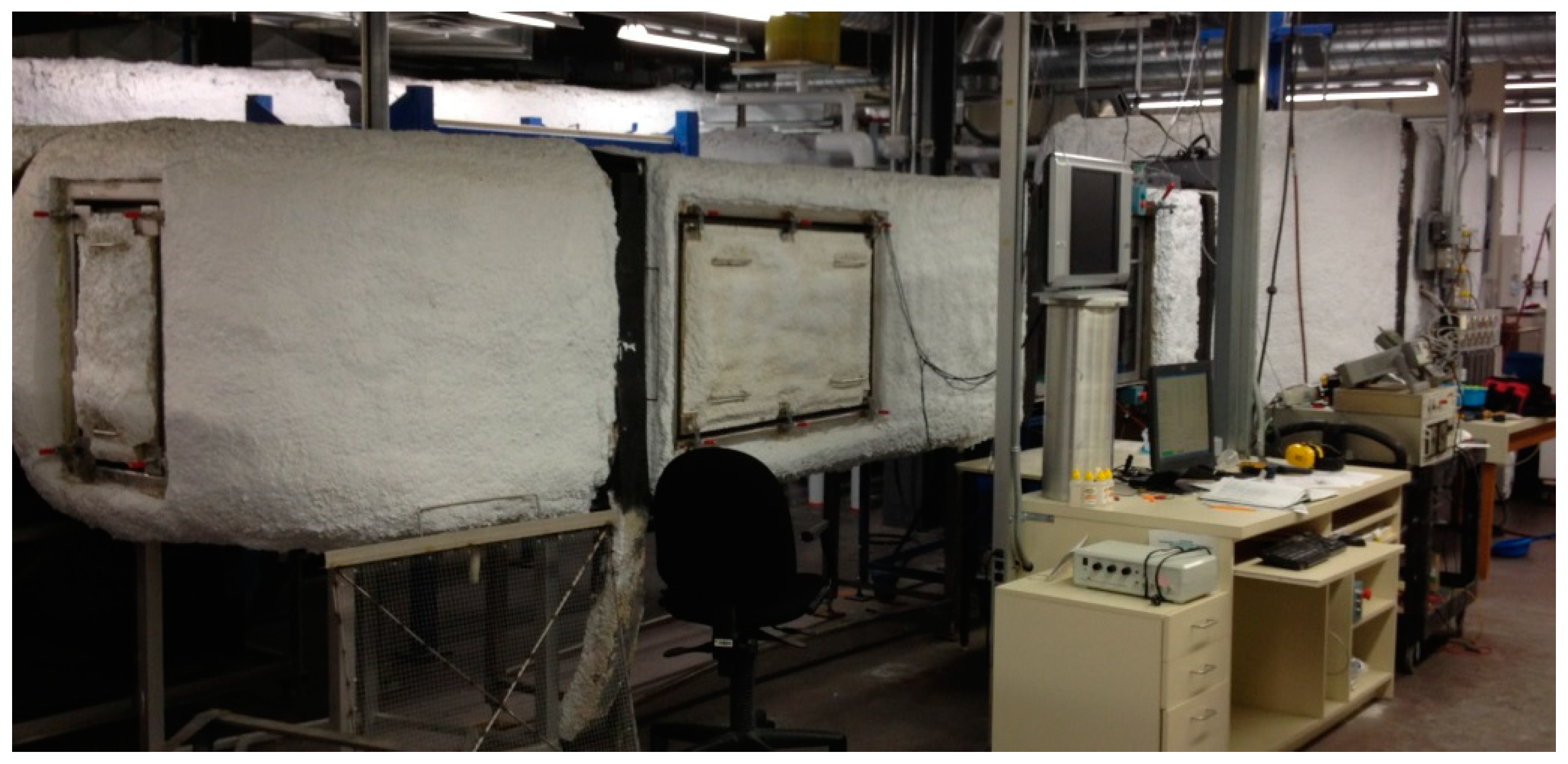
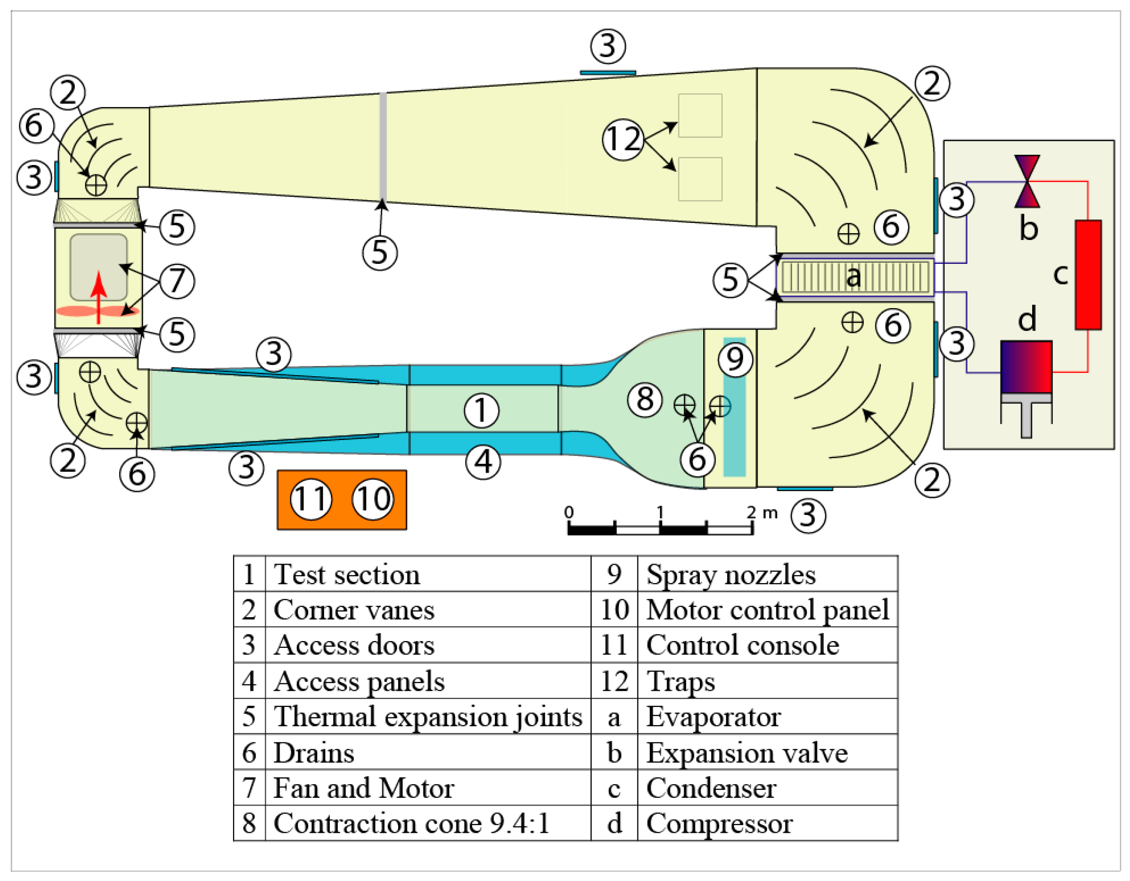
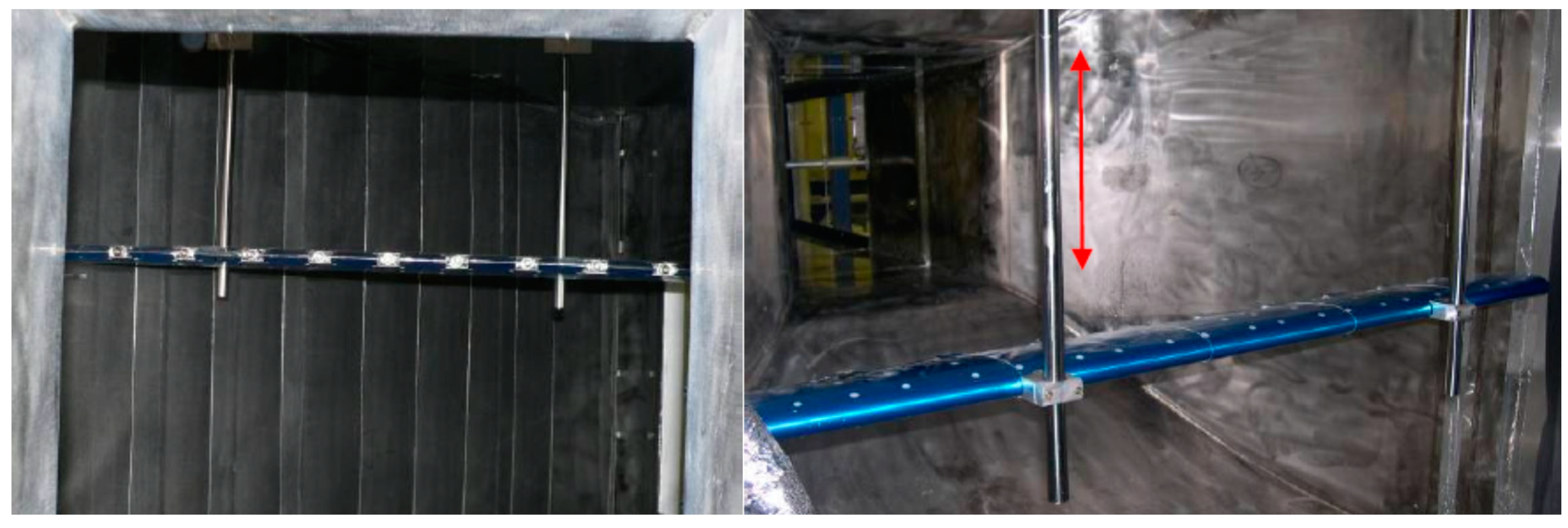
A lot of research and experimentation still needs to be done on ice protection systems for rotorcraft. Several setups have been developed over the past decades to study the icing on rotorcraft blade. The Anti-icing Materials International Laboratory (AMIL) at the Université du Québec à Chicoutimi had previously developed the spinning rotor blade (SRB) to evaluate ice shapes and measure the ice adhesion on different surface coatings applied to scaled-down rotorcraft blade in rotation submitted to representative atmospheric icing [
3]. Wang et al. [
4] conducted experiments using a rotating blade in a cold chamber, under various icing conditions. The ice shapes, the influence of different icing temperatures, rotation speeds, liquid water content, icing times, number of blades on the rotor and blade material were analyzed. Liu et al. [
5] investigated the dynamic ice accretion into an icing wind tunnel on a rotating propeller model. The power consumption measurements revealed that the propeller consumes more power under icing conditions. The National Research Council (NRC) has developed an in-situ rotating ice adhesion rig installed in the Altitude Icing Wind Tunnel (AIWT) [
6] to measure the adhesion properties of ice to various icephobic coatings [
7]. In this setup, the samples are iced when fixed or at very slow rotation speeds. Once the ice is accreted, the rotation speed is linearly increased until ice is detached. However, no power can be supplied to the blades in rotation with those setups and they cannot be used to test active ice protection systems. Laroche [
8] studied the thermal efficiency, and temperature uniformity of three different heating element materials. Tests were performed on flat heater coupons in an icing wind tunnel but not in rotation. Antonini et al. [
9] studied the effect of superhydrophobic coatings on surfaces exposed to icing conditions. All tests were performed in an open loop icing wind tunnel on a standard NACA0021 airfoil, fixed, and equipped with an electrical heater mounted on a leading edge. Those setups allow testing of active ice protection systems but are limited to fixed wings only.
Palacios et al. [
10,
11] presented a novel pneumatic approach to protect helicopter rotor blades from ice accretion. Testing was conducted in the Adverse Environment Rotor Test Stand Facility [
12], which is capable of generating icing in a cold room on rotating blades. This test setup allowed Palacios [
13] to design, fabricate, and test a low-power, non-thermal, ultrasonic de-icing system as a potential replacement of current electro-thermal systems on helicopter rotor blades. The proposed de-icing actuator system however remained conceptual. While this setup is able to test active protection systems in rotation, it is not installed in a wind tunnel and cannot generate representative atmospheric icing conditions at various wind speed, simulating forward flight. Li [
14] by using the Icing Research Tunnel of Iowa State University (ISU-IRT), conducted a series of experimental studies in order to investigate the dynamic ice accretion process on the surface of three different kinds of aero-engine spinner-fan models and to explore the feasibility of different anti-/de-icing technologies. In this study, a superhydrophobic coating was used for icing mitigation and also the anti-/de-icing performance using a hot air circulating system was evaluated. In this setup, only hot air can be used for active ice protection, no other source of energy can be supplied to the blade.
Huang et al. [
15] reviewed the state-of-the art of icephobic coatings for various applications and their efficiency. Despite the promising results obtained with coatings, Huang suggested that they should be considered as a complementary option to either thermal or mechanical ice protection methods. Therefore, following a quick analysis of these assemblies, none of them can be used to test active ice protection systems subjected to atmospheric icing in an icing wind tunnel on rotating blades. None of them can perform testing on hybrid systems, combining active and passive methods, or assess the effectiveness of an icephobic coating combined with thermal heating or another mechanical/active method applied to the leading edge of rotating helicopter blades. To address this need, AMIL has decided to modify its SRB Setup [
3] in order to be able to bring electric power to various devices like heating elements, conductive coatings or piezoelectric elements installed on the rotating blades. This new device will now allow, among other things, to measure heat transfer, force magnitudes, ice nucleation, and thermal equilibrium during ice accretion, different innovative thermal protection systems (conductive coating, carbon nanotubes, impulse, etc.), as well as mechanical systems. This paper presents the design and construction of the modified setup as well as the preliminary test campaign performed to validate the efficiency of the resulting system. In this preliminary test campaign, different surface coatings are applied to thermally protected blades in order to measure their impact on the protection of the blades.
3. Results
This section presents the different results obtained during experimentation with the bare aluminum blades and with the blades covered with the four different coatings. Results are separated in two different sections, one for the test performed under an anti-icing mode and one for those performed under a de-icing mode. In anti-icing mode, power supplied to the blade is gradually lowered until traces of ice starts to appear on the whole leading edge while in de-icing mode, an ice layer is first accreted and power supplied to the elements is gradually increased until ice shedding is obtained from the test blade. Problems were encountered with the signals from the RTDs and temperature measurements could not be done for these series of testing. Signals received from the slip ring was intermittent and would suddenly vary significantly to inconsistent values. Troubleshooting has to be done to fully understand the problematic and correct it before a next test campaign.
3.1. Anti-Icing
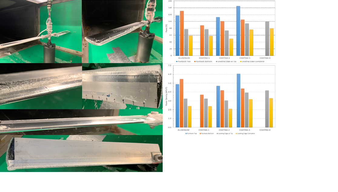
This section presents the results obtained in Anti-icing mode. During those tests, the blades are put in rotation in the wind tunnel. Maximum power is then supplied to the blade in order to ensure no ice accumulation on the blade. Water spraying is then initiated in the tunnel and then power is decreased gradually until ice is accreted on the whole leading edge of the blade. During this process, the power is recorded at four important steps: (1) when runback water appears on top of the blade and (2) at the bottom of the blade, (3) when ice is first witnessed at the tip of the blade, and (4) when the leading edge is first entirely covered with ice (complete radius). As opposed to de-icing, in anti-icing usually no ice accretes on the blades. Those steps represent the different accumulation that can occur on the blade which all need to be prevented and the power measured show the minimum power to prevent that particular accumulation. Separating the tests this way helps highlight the different power required for each accumulation as well as the different ways a coating can help reduce total power consumption, (for example: when preventing runback accumulation).
Figure 9 shows pictures of steps 1–4 taken with a video camera during testing. The steps are defined in the order they are expected to be encountered most of the time (based on experiences), but the order and/or occurrence of the steps can vary depending on the test and coating behaviors.
3.1.1. Air Temperature of −7.5 °C
All the coatings are first tested at an ambient air temperature of −7.5 °C in the wind tunnel. At this air temperature with the other test conditions selected (LWC, MVD, RPM, etc.), the ice accretion obtained is a glaze ice, as shown under
Section 3.2.1. Three test repetitions are performed with each substrate.
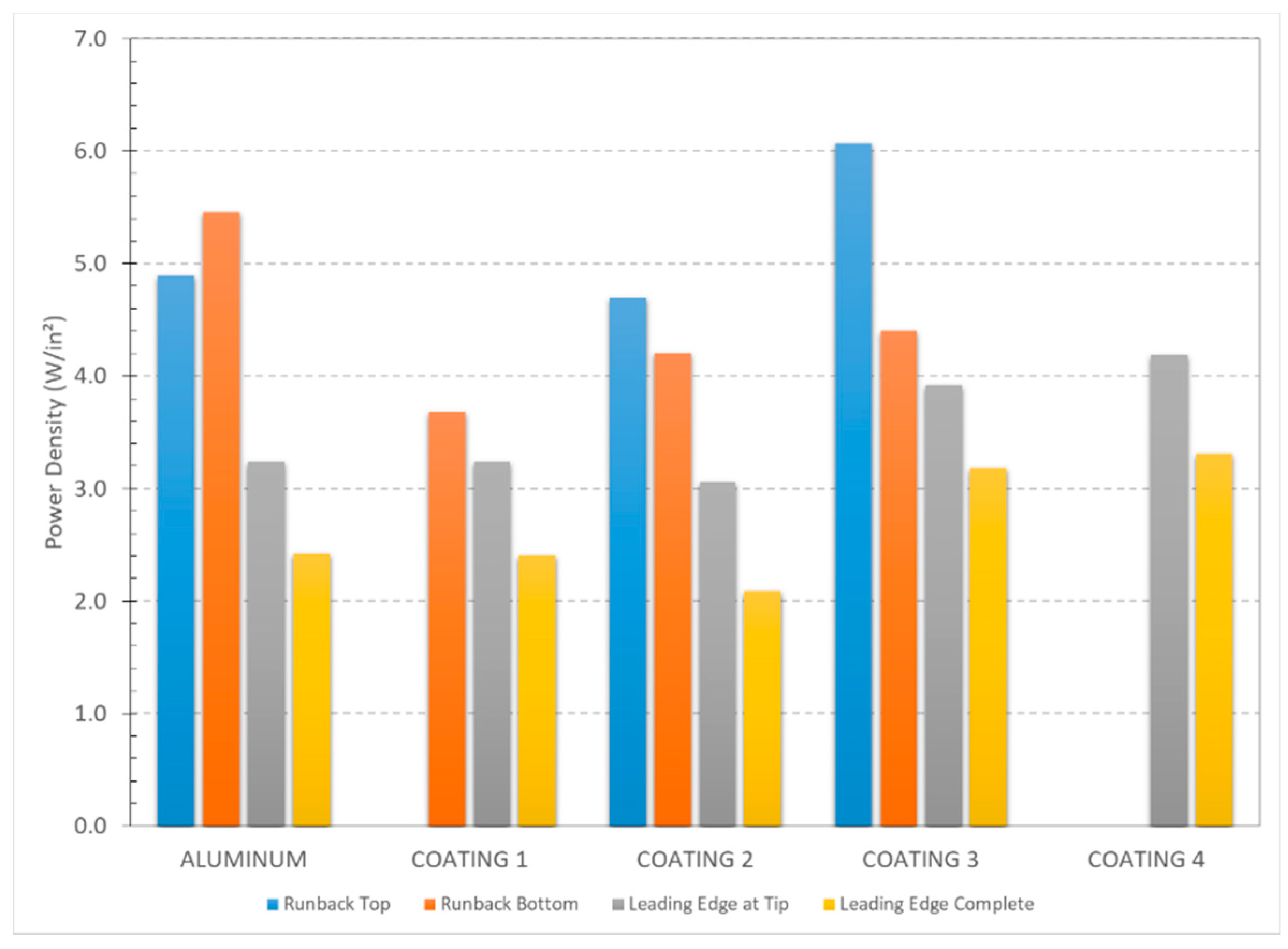
Figure 10 presents the power density for the different substrate at steps 1 to 4 during testing that is calculated by dividing the total power consumption by the surface area of the heating elements (2 × 1 × 12 in²).
For the case of runback on the top of the blade, the power and power density are 118 ± 7 W and 4.9 ± 0.3 W/in² for the Aluminum, 113 ± 11 W and 4.7 ± 0.5 W/in² for Coating 2, 145.6 ± 27 W and 6.1 ± 1.1 W/in² for Coating 3 while no runback is obtained with Coatings 1 and 4.
For runback on the bottom, the power and power density are 131 ± 8 W and 5.5 ± 0.4 W/in² for Aluminum, 88 ± 7 W and 3.7 ± 0.3 W/in² for Coating 1, 101 ± 20 W/in² and 4.2 ± 0.8 W/in² for Coating 2, 105.7 ± 23 W/in² and 4.4 ± 1.0 W/in² for Coating 3, and no runback for Coating 4.
For the initiation of the ice accumulation on the leading edge at the tip of blade, the power and power density are 78 ± 8 W and 3.2 ± 0.4 W/in2 for the aluminum, 78 ± 1 W and 3.2 ± 0.1 W/in2 for Coating 1, 73 ± 6 W and 3.1 ± 0.3 W/in2 for Coating 2, 94.1 ± 12 W and 3.9 ± 0.5 W/in2 for Coating 3, and 100 ± 1 W and 4.2 ± 0.1 W/in2 for Coating 4.
Finally, for an ice accumulation on the whole leading edge, the power and power density are 58 ± 9 W and 2.4 ± 0.4 W/in2 for the aluminum, 58 ± 2 W and 2.4 ± 0.1 W/in2 for Coating 1, 50 ± 9 W and 2.1 ± 0.4 W/in2 for Coating 2, 76.3 ± 5 W and 3.2 ± 0.2 W/in2 for Coating 3, and 79 ± 4 and 3.3 ± 0.1 W/in2 for Coating 4.
The results show a diminution of the power between each step except for the aluminum between steps 1 and 2, where runback first accreted at the bottom of the blade. For Coating 1, no runback was obtained on the top of the blade during the whole test, while for Coating 4 no runback accumulated on the blade at all, only at the leading edge (
Figure 11). For the ice accumulation on the leading edge, only Coating 2 shows a reduction in power consumption as compared to aluminum, while the other coatings all increased the power required to maintain the leading edge free of ice.
3.1.2. Air Temperature of −15 °C
Testing is repeated with the same test procedure but with an ambient air temperature of −15 °C. Due to time limitation only aluminum and Coating 2 were tested. Coating 2 is selected since it is the only coating that showed a power reduction for the accumulation on the leading edge. Testing is repeated three times for each of the two substrates. At this temperature and other test conditions selected, ice accretion obtained was a mixed ice, a combination of clear and rime ice (see
Section 3.2.2).
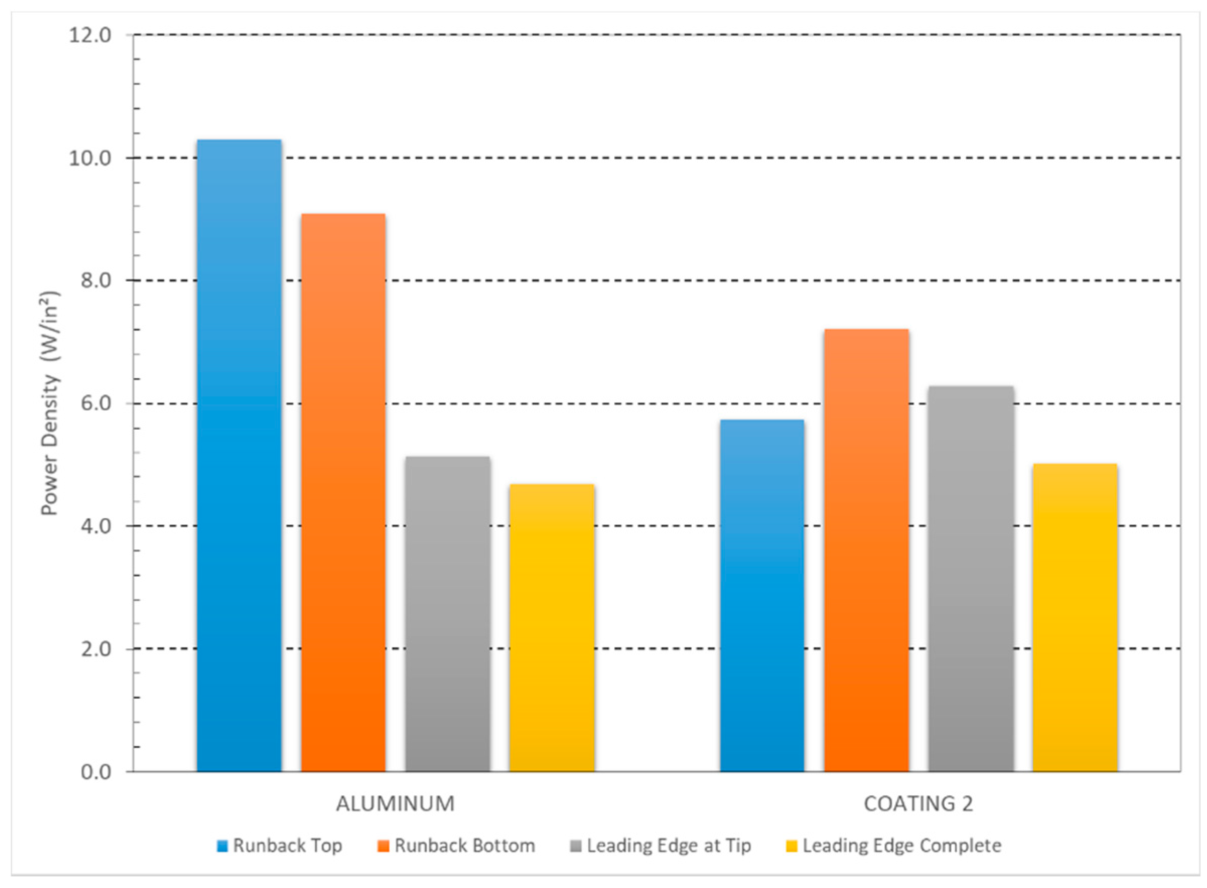
Figure 12 presents the power density consumed for the aluminum and Coating 2 at steps 1 to 4. For Runback on the top of the blade, the power and power density are 247 ± 21 W and 10.3 ± 0.9 W/in² for the aluminum and 138 ± 16 W and 5.7 ± 0.7 W/in² for Coating 2. For runback on the bottom, the power and power density are 218 ± 12 W and 9.1 ± 0.5 W/in² for aluminum and 173 ± 16 W/in
2 and 7.2 ± 0.7 W/in
2 for Coating 2. For the initiation of the ice accumulation on the leading edge at the tip of the blade, the power and power density are 123 ± 1 W and 5.1 ± 0.1 W/in
2 for the aluminum and 151 ± 35 W and 6.3 ± 1.5 W/in² for Coating 2. Finally, for an ice accumulation on the whole leading edge, the power and power density are 112 ± 8 W and 4.7 ± 0.3 W/in
2 for the aluminum and 120 ± 12 W and 5.0 ± 0.5 W/in
2 for Coating 2.
As opposed to the results at −7.5 °C, a decrease of the power between each step is obtained for the aluminum but not between steps 1 and 2, where runback first accreted at the bottom of the blade, for Coating 2. Also, Coating 2 does not allow a power consumption reduction when compared to aluminum at this temperature.
3.2. De-Icing
In this section, the results obtained under a de-icing regime are presented. For those tests, blades are put in rotation in the wind tunnel and the air temperature is stabilized. Then, the icing cloud is generated in the test section and ice starts accumulating on the rotating blade. Icing in the tunnel is stopped when an ice thickness of 6 mm is obtained at the tip of the blade, which corresponds to the maximum thickness allowed on the main rotor blades of a rotorcraft studied in this project. To obtain the desired ice thickness, accumulation is done on the rotating blades prior to testing and the ice thickness is measured with a caliper. The time to reach the desired thickness is recorded and used to define the icing time for the different tests at each condition. This process was repeated multiple times at each single condition to ensure that the method provides repeatable ice thicknesses and the resulting thickness only varied by less than 0.6 mm, which was considered acceptable. After the ice accumulation, minimum power is supplied to the heating elements and gradually increased until shedding the ice layer from the test blade. Ice shedding is detected by the sound of the ice impacting on the tunnel walls and by a significant vibration spike measured by an accelerometer installed on the setup for vibration surveillance. Shedding is when ice the complete ice layer accreted on the leading edge detaches from the blade, besides the small residual part at the root of the blade. Power is recorded throughout the test.
3.2.1. Air Temperature of −7.5 °C
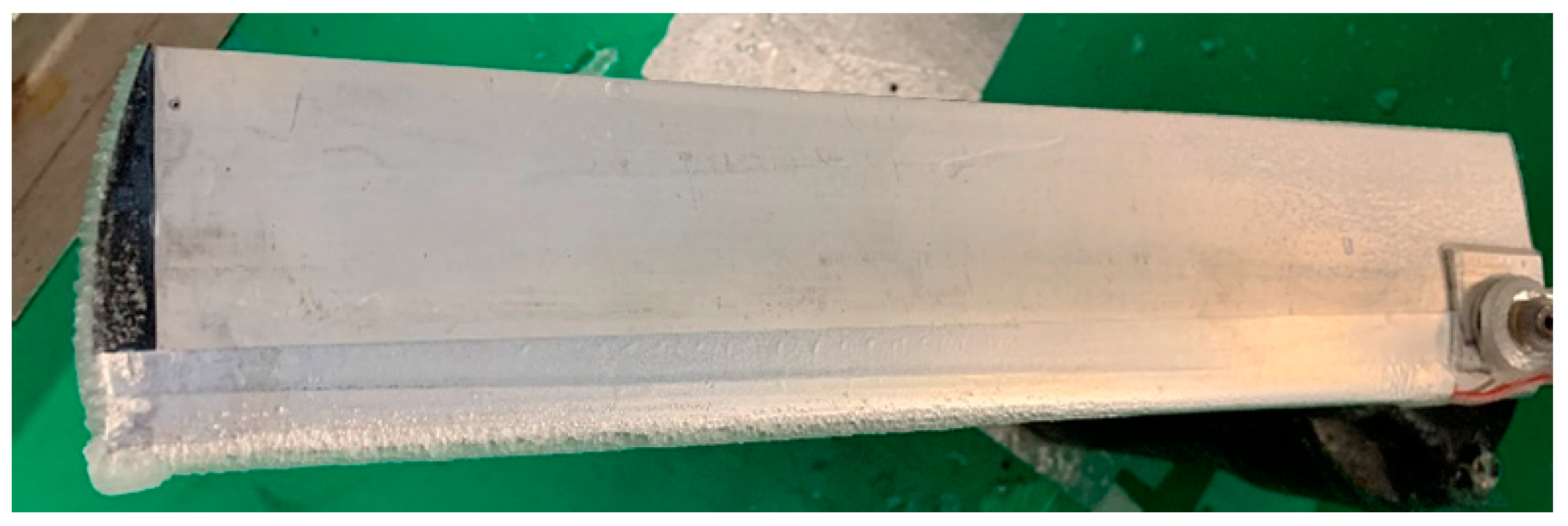
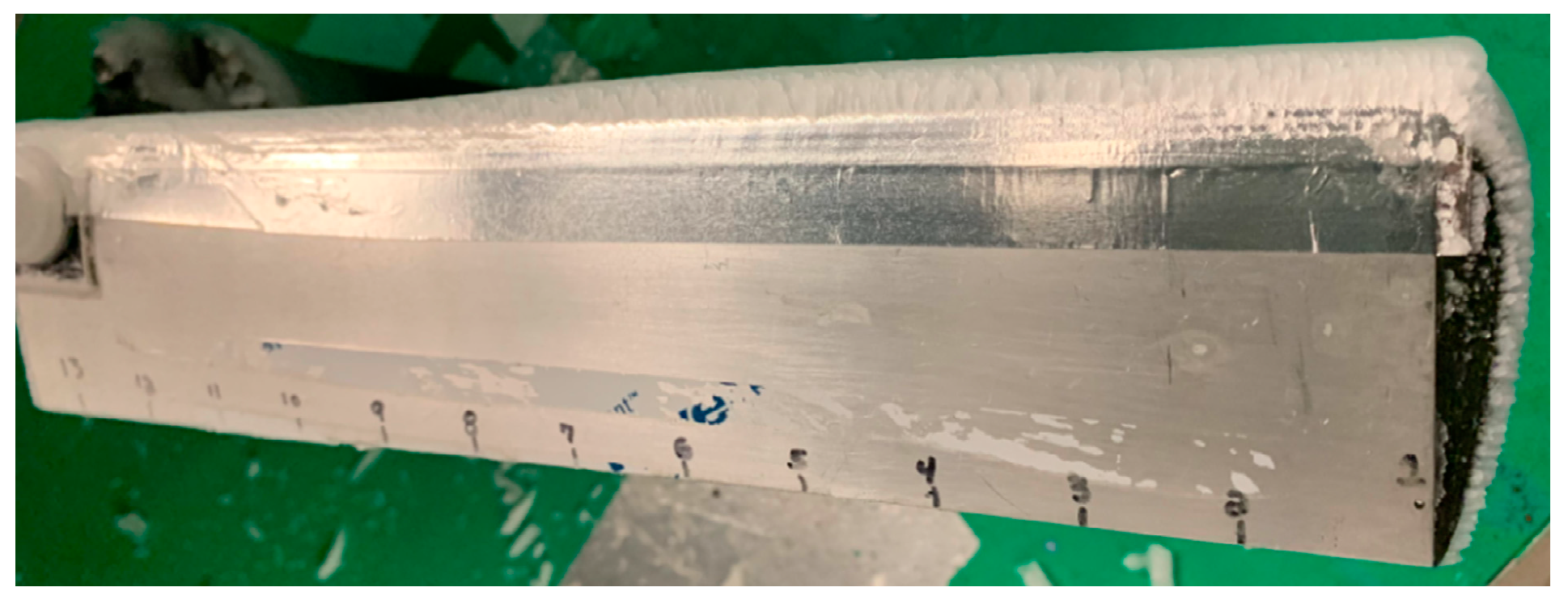
As for the tests in Anti-icing mode, testing is performed with bare aluminum blades and with the four different coatings at −7.5 °C. Ice accumulation obtained is, again, for those test conditions a glaze ice accumulation. Ice thickness varies along the radius of the blade due to the tangential velocity increase with the radial position. Resulting ice accumulation is shown at
Figure 13.
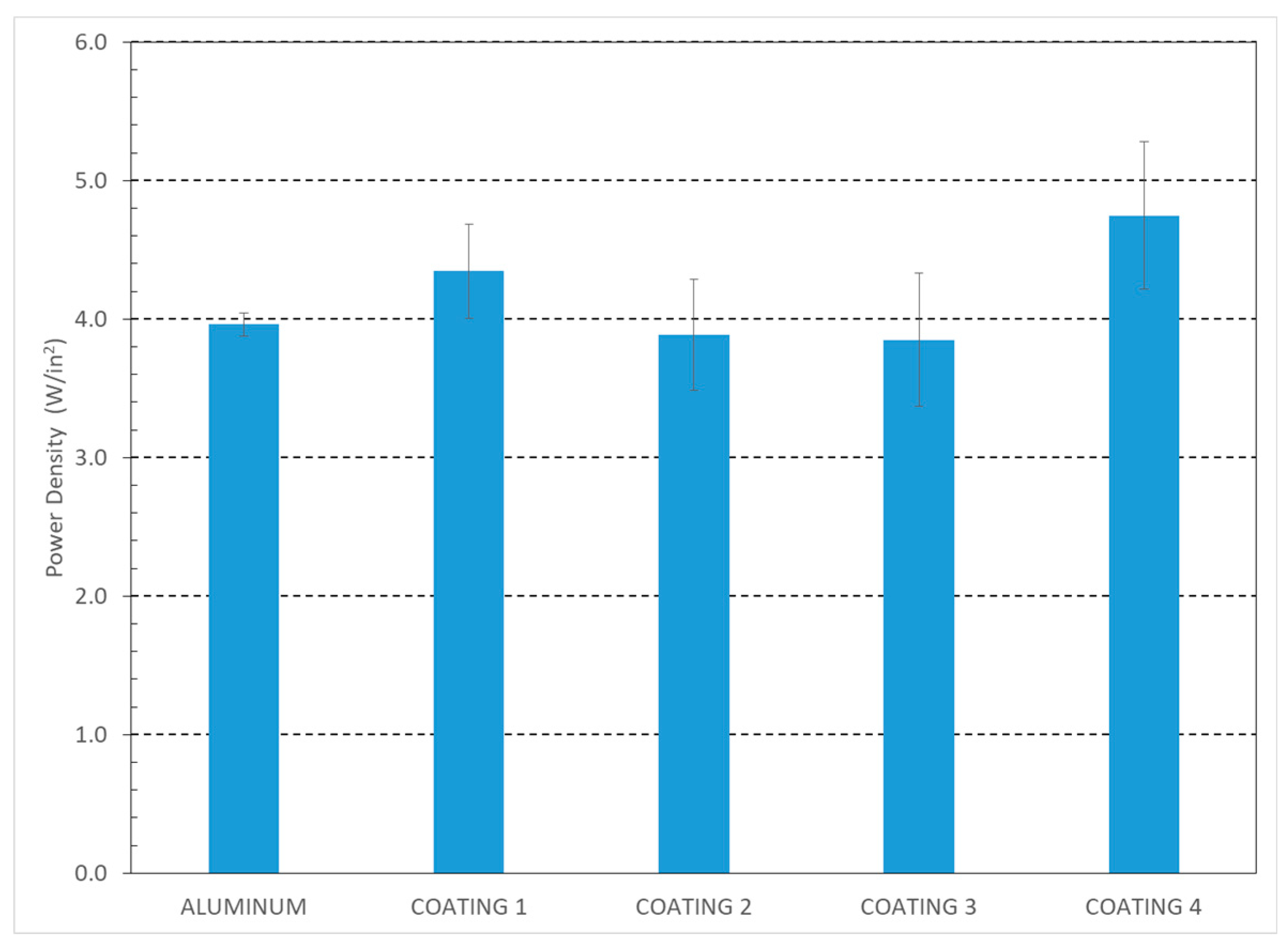
Testing is repeated three times for each substrate and the average power density obtained for all the different substrates is presented in
Figure 14. The total power consumption for the aluminum is 95.1 ± 2.0 W with a power density of 4.0 ± 0.1 W/in
2, while it is 104.3 ± 8.2 W with a power density of 4.3 ± 0.3 W/in
2 for Coating 1, 93.3 ± 9.6 W with a power density of 3.9 ± 0.4 W/in
2 for Coating 2, 92.4 ± 11.6 W with a power density of 3.9 ± 0.5 W/in
2 for Coating 3 and 113.9 ± 12.8 W with a power density of 4.7 ± 0.5 W/in
2 for Coating 4. A small reduction in power as compared to aluminum is obtained for Coatings 2 and 3. However, when looking at the three test repetitions for Coating 3, it can be observed that the coating suffers degradation throughout testing. The first result obtained is 79.5 W, significantly lower than aluminum, while for the second and third test the power consumption increases to 95.9 and 101.8 W, which is higher than the case of bare aluminum.
3.2.2. Air Temperature of −15 °C
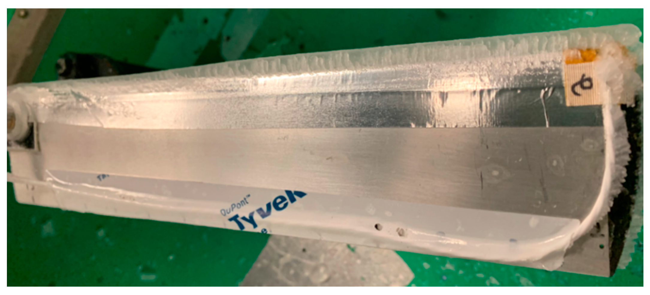
Testing is also performed at −15 °C but due to time restriction, only bare aluminum and Coating 2 are tested. Coating 3 is not tested because of the resulting degradation from testing at −7.5 °C. The ice accumulation obtained is a mixed ice which is a combination of clear and rime ice (
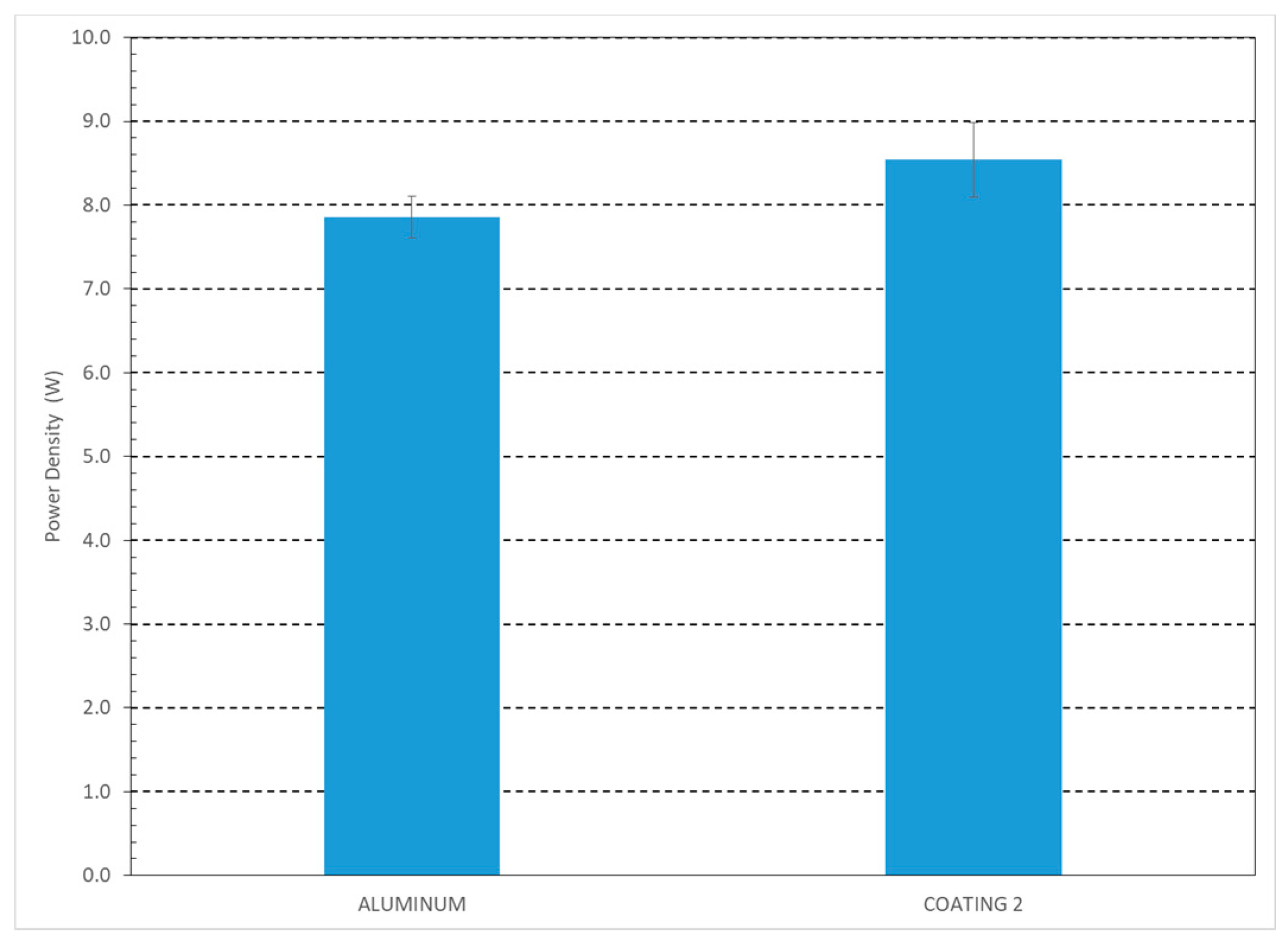
Figure 15). Three test repetitions are performed with each substrate and the power densities obtained are presented at
Figure 16. For the aluminum the power is 188.6 ± 6.0 W with a power density of 7.9 ± 0.3 W/in
2. For Coating 2, the power consumption and density are higher than for aluminum with values of 205.0 ± 8.5 W and 8.5 ± 0.4 W/in
2, respectively.
4. Discussion
In this section, the impact of the coatings on an electrothermal ice protection system, whether working in anti-icing or in de-icing mode, is analyzed when compared to bare aluminum blades.
4.1. Anti-Icing Mode
The power difference for each step between the coatings and the bare aluminum blades are presented at
Table 4. Besides Coating 2 at −7.5 °C, the coatings either increased the power required to protect the leading edge of the blade or had no effect. At −15 °C, Coating 2 did not improve the system’s performance and the power was as high as for the other coatings at −7.5 °C. This power increase could be attributed to the additional insulation that the coating layer brings between the surface and the heating element. This coating is epoxy based and epoxy is known to be a good insulator, being more than 1000 times less thermally conductive than aluminum. It would be interesting to measure this insulation and determine a correlation between these results and the added insulation. This conclusion signifies that once insufficient power is supplied to prevent nucleation of the water droplets at impact on the leading edge, the coatings tested have no positive impact on the system. This is in accordance with the accumulation obtained at the leading edge and the ice accumulation obtained in de-icing mode. As detailed in the next section (
Section 4.2), the ice accumulates at a similar rate when no power is supplied in de-icing mode and the resulting accumulation is similar on all substrates, showing that the coatings tested have no effect on ice accumulation.
On the other hand, the coatings tested significantly affected the runback effect on the blades. Except for the runback on the top of the blade with Coating 3, all the coatings reduced the power by up to 44% before runback started accumulating. For Coating 4, no runback was at all accumulated for the three test repetitions performed; while for Coating 1, no runback accumulated on the top of the blade. This means that when the power is sufficient to prevent freezing of the droplets and allow flow off from the leading edge, the hydrophobic nature of the coatings tested facilitate water flow off from the blade. The superhydrophobic coatings (1 and 4) even completely prevent runback accumulation on the blade (upper surface only for Coating 1). This can lead to a significant positive effect on an ice protection system in anti-icing mode. For example, if Coating 4 is applied, instead of having to supply more than 131 W to prevent any ice accumulation, including no runback, on the blade, only around 100 W are required, which is a power reduction of 24% of the power consumed by the system. If Coating 4 could be applied on the leading edge only (resulting in no added insulation over the heating elements) and still provide the same benefit of better water flow off (which is plausible but has yet to be demonstrated) the power could be reduced to 78 W. This represents a power reduction of 40% which is very significant for such systems, considering the limited power available on a rotorcraft.
4.2. De-Icing Mode
In de-icing mode, an ice layer is first accumulated on the blades before power is supplied to the heating elements. As mentioned in the previous section, the accumulation rate is similar for all substrates and increases linearly with the radius. Also, the type of ice accumulation is the same on all substrates and resulting accumulations do not show any difference for any substrate. This tends to confirm the conclusion obtained in anti-icing mode that the coatings tested do not provide any benefit when the power is not sufficient to prevent water droplets impinging from freezing on the leading edge.
The power difference to generate ice shedding from the blade as required by the coatings and compared to bare aluminum blades is presented at
Table 5. The results show that the presence of the coatings tested has a very minor effect on the power required for ice shedding from the blade. Coating 4 increases the power required by 20%, while all other surfaces impact the power by less than 10%, which is close to the experimental variability. The coatings tested were not—or very slightly—icephobic, as shown by their ARF values (
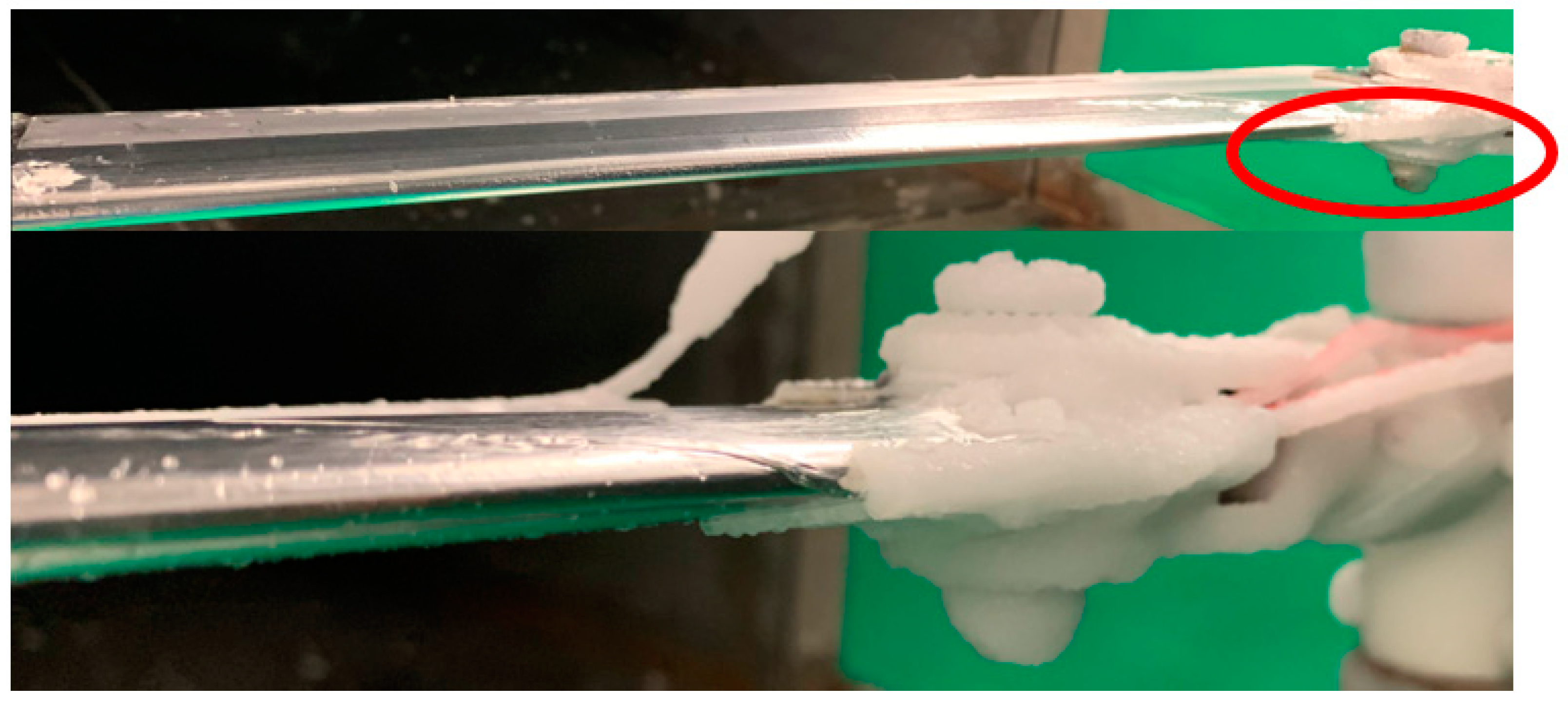
Table 2), meaning that they do not significantly reduce the adhesion of the ice. This can explain this slight effect on the power consumption at shedding. It would be interesting to pursue testing on coatings showing high icephobicity. Also, a small zone at the root of the blade exists where there is no wire in the heating element resulting in no heating. At this position, the ice stays anchored to the blade and a cohesive break has to occur within the ice layer for ice shedding. A short part of the ice layer remains on the blade as shown at
Figure 17. This is expected to have an influence on the results obtained, which could be part of the reasons for the uniform results for all the substrates. These preliminary experiments have allowed to observe this phenomenon and will allow further improvement of the setup. By improving the setup, it will be possible to quantify this effect and increase the fidelity of the results.
5. Conclusions
This paper presents the design and development of a new test setup to perform experimental testing of different powered ice protection systems on rotating blades. By modifying an existing setup at the laboratory, it was possible to bring electric power to the rotating blades in a wind tunnel submitted to different representative atmospheric icing clouds. After the completion of the setup, preliminary testing was done to test the new apparatus. An electrothermal ice protection system was tested at two temperatures and compared with a hybrid version of the same system where hydrophobic/superhydrophobic coatings were applied at the surface with the hope of reducing power consumption due to the water repellant properties of the coatings. This made it possible to measure their impact on the system performance when compared to the standard system. Tests were performed in both anti-icing and in de-icing mode.
In anti-icing, the coatings tested did not show any improvement on the power consumption to keep the leading edge of the blade, where the ice accumulation occurs, free of ice. On the other hand, all the coatings tested reduced the power required to keep the blade completely clean without any runback ice accumulation. One of the coatings totally prevented runback accumulation. That coating could reduce power consumption in anti-icing by up to 44% if only applied away of the leading edge and on the rest of the blade, which is significant with the limited power available on rotorcraft. This showed that the coatings tested had no positive effect when the droplet freezes at impact on the leading edge, but were effective when the droplets were kept in a liquid form and could flow off the leading edge favoring their flow off from the blade.
In de-icing, the results were similar for all the substrate tested, including for the bare aluminum blades. The low icephobicity of the coatings tested could explain this result. Testing with highly icephobic coatings should be done to see if a more significant impact could be obtained with such coatings. It was observed that, due to a small unheated zone at the root of the blade, a short part of the ice accumulation did not shed from the blade increasing the force required for ice shedding to generate the cohesive break in the ice layer itself. Improvements must be made to the setup to prevent this effect and increase the accuracy of the results. Also, additional camera systems—including thermal and IR cameras—will be mounted on the wind tunnel for better imaging of the tests. Preliminary investigation with one thermal and/or IR camera will be done first to assess the advantages of using such a device, and if the results are positive, a complete camera system which could include multiple thermal/IR cameras mixed with standard video cameras will be designed to optimize visualization of the different processes involved at different key angles.
The developed setup proves successful for the testing of an electrothermal ice protection system in anti-icing mode; while in de-icing mode slight improvements must be made to increase their accuracy. The improvements are minor and the results are still deemed reliable and repeatable even for preliminary experiments, with an experimental variability below 15% for the tests on bare aluminum. With this successful proof-of-concept, this new experimental test setup will allow the design, testing, and characterization of different ice protection systems for small scale tests under representative atmospheric icing. The next step, after making the improvements required, will be to test a mechanically operated-icing system for rotorcraft, which will be presented in a future publication.


