
Development of a Flexible and Expandable UTM Simulator Based on Open Sources and Platforms


1
ModelSim, Inc., Rm 208, E-TON Tower III, Neungdong-ro 18, Gwangjin-gu, Seoul 05096, Korea
2
Agency for Defense Development, 160 Bugyuseong-daero 188 Beon-gil, Yuseong-gu, Daejeon 34060, Korea
3
LIGNex1 Co., Ltd., 333 Pangyo-ro, Bundang-gu, Seongnam-si, Gyeonggi-do 13488, Korea
*
Author to whom correspondence should be addressed.
Aerospace 2021, 8(5), 133; https://0-doi-org.brum.beds.ac.uk/10.3390/aerospace8050133
Submission received: 10 April 2021
/
Revised: 30 April 2021
/
Accepted: 30 April 2021
/
Published: 8 May 2021
Abstract
:In order to study air traffic control of UAS’s (Unmanned Aerial Systems) in very low altitudes, the UTM (UAS Traffic Management) simulator has to be as flexible and expandable as other research simulators because relevant technologies and regulations are not matured enough at this stage. Available approaches using open sources and platforms are investigated to be used in the UTM simulator. The fundamental rationale for selection is availability of necessary resources to build a UTM simulator. Integration efforts to build a UTM simulator are elaborated, using Ardupilot, MavProxi, Cesium, and VWorld, which are selected from the thorough field study. Design requirements of a UTM simulator are determined by analyzing UTM services defined by NASA (National Aeronautics and Space Administration) and Eurocontrol. The UTM simulator, named eUTM, is composed of three components: UOS (UTM Operating System), UTM, and multiple GCSs (Ground Control Stations). GCSs are responsible for generation of flight paths of various UASs. UTM component copies functions of a real UTM such as monitoring and controlling air spaces. UOS provides simulation of environment such as weather, and controls the whole UTM simulator system. UOS also generates operation scenarios of UTM, and resides on the same UTM computer as an independent process. Two GCS simulators are connected to the UTM simulator in the present configuration, but the UTM simulator can be expanded to include up to 10 GCS simulators in the present design. In order to demonstrate the flexibility and expandability of eUTM simulator, several operation scenarios are realized and typical deconfliction scenarios among them are tested with a deconfliction algorithm. During the study, some limits are identified with applied open sources and platforms, which have to be resolved in order to obtain a flexible and expandable UTM simulator supporting relevant studies. Most of them are related to interfacing individual sources and platforms which use different program languages and communication drivers.
1. Introduction
UTM (Unmanned aircraft system Traffic Management) is a concept that brings an automated ATM (Air Traffic Management)-like system to very low level airspace which will be occupied primarily by unmanned aircrafts weighing less than 25 kg (commonly referred to as drones). A number of conceptual frameworks, platform architectures, methodologies, and practical demonstrators have been developed across the globe over the last few years to attempt to tackle the complex challenge of how all of this civilian UAS (Unmanned Aerial System) traffic management activity is actually going to work. These activities are in response to modern world expectations and commercial service demands, and are counterbalanced by technology developments and regulated operation.
Three major initiatives are the USA’s UTM (Unmanned Aircraft Systems Traffic Management) system developed at NASA’s Ames Research Center [1], U-space developed by SJU (Single European Sky ATM Research Joint Undertaking) [2], and JARUS (the Joint Authorities for Rulemaking on Unmanned Systems). Other similar UAS traffic management frameworks to UTM/U-Space models include UOMS (the Civil UAS Operation Management System) [3] in China and Japan’s JUTM (UTM Consortium) [4]. These UTM/U-Space frameworks are supported by real-world demonstrations and testing through the NASA (National Aeronautics and Space Administration) TCL (Technology Capability Level), UPP (FAA UTM Pilot Program), and IPP (UAS Integration Pilot Program) demonstrations in the USA, and the European Network of U-Space Demonstrator in Europe, overseen by Eurocontrol and SESAR (Single European Sky ATM Research).
In order to support UTM studies, simulators are included in most relevant research programs. There are two different approaches in developing UTM simulators; one is to use proprietary solutions and the other is to rely on open sources and platforms. Aforementioned USA and European initiatives prefer to use their own assets because they have already worked on ATC/M (Air Traffic Control/Management) for many years. Some private companies such as OneSky and Airbus also promote their proprietary simulators. The second approach is based on open sources and platforms, which is preferred by small research sectors and academia because they can concentrate on UTM-relevant researches, not putting much labor and expenses into building simulator platforms and tools. UTM simulator studies include “A Simulation Framework for Fast Design Space Exploration of Unmanned Air System Traffic Management Policies” [5], “UAS Traffic Management (UTM) Simulation Capabilities and Laboratory Environment” [6], “A UTM simulator based on ROS and Gazebo” [7], and U-Flyte’s UTM Simulator [8].
The primary goal of this simulator, named eUTM Simulator, is to provide a research platform to study deconfliction algorithms of UAS for BVLOS (Beyond Visual Line Of Sight) and VLOS (Visual Line Of Sight) flights in the very low altitudes where civil UASs are allowed to fly. The second goal is to be used in designing pre- and in-flight UTM procedures. The third goal is to verify and support UTM relevant regulations. In order to support these objectives, the simulator has to be as flexible and expandable as other research simulators because these tasks are not matured enough at this stage. The critical constraint in developing a UTM simulator is limited available resources, but the simulator has to be built quickly to come up with international research activities. Thus, approaches using open sources and platforms are investigated. Five UAS simulation frameworks turned out to be available for eUTM Simulator: AirSim [9], Gazebo [10], jMavsim [11], ROS (Robotics Operating System) [12], and Ardupilot/Mission Planner/MavProxi [13]. Three-dimensional visualization with geoinformation for UAS flights is another issue to be considered because of their low-altitude flights under 150 m from the ground. There exist open platforms to provide 2D/3D visualization services such as Google Earth, Microsoft Bing map, and Airmap [14], which is dedicated to UAS. There has also been a national project, VWorld [15] for years in South Korea to build a virtual space of Korea for supporting researches regarding UAS, UAM (Urban Aerial Mobility), intelligent automobiles, and so on. Among these open sources and platforms, the simulation framework of Ardupilot/Mission Planner/MavProxi and VWorld-Cesium-based [16] visualization was selected in developing eUTM simulator. The fundamental rationale was availability of necessary resources to build a UTM simulator. Ardupilot and PX4 [17] are autopilots loaded on Pixhawk flight controller hardware and many multicopter drones are based on either Ardupilot or PX4, not just in South Korea, but internationally. Replacing physics models in the simulator by real UASs, a GCS (Ground Control Station) can be realized because the same autopilot can be shared in both simulator and real UAS [18]. VWorld provides UAS relevant information such as local geofence and prohibited flight zones, which are critical factors in UTM simulation, while other public visualization platforms do not provide realistic geoinformation of national airspace of South Korea. Map services of Cesium were adopted in eUTM simulator rather than those of VWorld because of shortage of necessary communication drivers and limits of inserting 3D objects in its 3D maps. For 2D and 3D visualizations of maps, air space information and graphic UAS models, GIS platforms of VWorld and Cesium are streamed and integrated in real time.
Integration efforts to build eUTM simulator were elaborated, using Ardupilot, Mission Planner, MavProxi, Cesium, and VWorld. Most of them are related to interfacing individual sources and platforms, which use different program languages and communication drivers. In order to demonstrate the flexibility and expandability of eUTM simulator, typical deconfliction scenarios [1] were also tested with a deconfliction algorithm [19]. During the study, some limits were identified with applied open sources and platforms, which have to be resolved in order to obtain a flexible and expandable UTM simulator supporting relevant studies. The technologies applied to the UTM simulator can also be utilized in smart GCS (Ground Control Station), UAS-based EW (Electronic Warfare), and real UTM systems. In order to demonstrate the applicability to EW, an aerial EW scenario was also generated.
2. Rationale for Selection of Open Sources/Platforms
The objective of this review is to determine the most reliable and effective UAS/UTM simulation architecture for research, industry collaboration, and product deployment, and the relevant analysis, which shall be applied to eUTM simulator. As mentioned in the introduction, there exist at least five UAS/UTM simulation frameworks based on open sources and platforms in the UAS community: AirSim, Gazebo, jMavsim, ROS, and ArduPilot—Mission Planner. AirSim is an open source, cross platform simulator for UAS, ground vehicles such as cars and various other objects, built on Unreal Engine 4 as a platform for AI research. AirSim is developed by Microsoft and can be used to experiment with deep learning, computer vision, and reinforcement learning algorithms for autonomous vehicles. Gazebo is an open source 3D robotics simulator. Gazebo integrates physics engine, OpenGL rendering, and support code for sensor simulation and actuator control. jMAVSim is a simple multirotor/quadcopter simulator that allows flying copter type vehicles running PX4 around a simulated world. It is easy to set up and can be used to test that a vehicle can take off, fly, land, and responds appropriately to various failure conditions. ROS (Robot Operating System) is robotics middleware (i.e., collection of software frameworks for robot software development). Although ROS is not an operating system, it provides services designed for a heterogeneous computer cluster such as hardware abstraction, low-level device control, implementation of commonly used functionality, message-passing between processes, and package management. ROS is familiar to the UAS community and provides appropriate drivers to communicate with most of the commercial autopilots. Moreover, ROS is integrated with Gazebo simulator, which has a large variety of available UAS models. These frameworks can be used for developing a UTM simulator. The main driving factor in selecting a UTM simulator platform is availability of resources to develop a simulator applicable to the national airspace of South Korea. Besides, most autopilots and ground control stations of real UASs are based on ArduPilot and Mission Planner in the international and Korean UAS communities, while very limited information is available for other aforementioned simulation frameworks. Thus, the simulation framework of Ardupilot/Mission Planner/MavProxi was selected in this research, with Mission Planner replaced by its short version, MavProxi, for real-time simulation. This is another criterion in selection of the simulator framework, which will lead to minimum discrepancy between real and virtual worlds. Besides, ArduPilot and Mission Planner have been used for years in mixed-reality-based GCS study, and have proven to be reliable for both real UAS’s FCC (Flight Control Computer) and virtual simulation [18].
ArduPilot is one of the most advanced, full-featured, and reliable open source autopilot software available in the UAS community. It is the autopilot software capable of controlling almost any vehicle system, from conventional airplanes, quadplanes, multirotors, and helicopters, to rovers, boats, and even submarines. The ArduPilot project is made up of ArduCopter, ArduPlane, ArduRover, ArduSub, and Antenna Tracker. ArduCopter is of special interest in this study, and can be used for simulation of multirotor/helicopter UASs. ArduCopter runs on ArduPilot (SW)/Pixhawk FCC (Flight Control Computer) HW. Adding GPS, this ArduPilot/Pixhawk becomes a complete UAS solution that sets it apart from traditional multirotors, which often only support remote control. The ArduCopter system features fully autonomous waypoint-based flight, with mission planning and real-time telemetry via the powerful ground control station. ArduCopter code is capable of controlling all of the major rotor wing airframes, including traditional helicopters, tricopter, quadrotor, hexa, and octa. SITL allows running ArduPilot on a desktop PC (Personal Computer) directly, without any special hardware. It takes advantage of the fact that ArduPilot is a portable autopilot that can run on a very wide variety of platforms. A PC is just another platform that ArduPilot can be built and run on. When running in SITL, the sensor data comes from a flight dynamics model in a flight simulator. ArduPilot has a wide range of vehicle simulators built in, and can interface to several external simulators. This allows ArduPilot to be tested on a very wide variety of vehicle types. Mission Planner is a ground control station for plane, copter, and rover. It is compatible with Windows only. Mission Planner can be used as a configuration utility or as a dynamic control supplement for an autonomous vehicle. MAVProxy is a fully functioning GCS for UASs, designed as a minimalist, portable, and extendable GCS for any autonomous systems supporting the MAVLink protocol (such as one using ArduPilot), and runs on any POSIX OS and Windows with python. MAVLink is a very lightweight messaging protocol for communicating with drones (and between onboard UAS components). Integrating ArduPilot SITL, ArduCopter, and MAVProxy with 3D visualization services, a UTM simulator based on open sources and platforms can be configured with additional modules to provide security, information, and flight services.
Three-dimensional visualization of geoinformation is important in UTM simulation due to UAS’s very low-altitude flight under 150 m height from the ground. There exist obstacles such as buildings, bridges, and so on, which are of no concern to manned airplanes and ATC/M. There exist several 3D visualization platforms providing users with SDKs for inserting 3D objects into the virtual spaces. Google Earth, Bing Map, and AirMap are good candidates for 3D visualization with geospecific information. The main issue in realizing a UTM simulator is whether it is easy or possible to insert geospecific information, restricted/prohibited airspace markers, geofences, 3D objects, and so on. Visual update rates and qualities are of concern, too. VWorld is also considered in this study because of availability of necessary tools and local airspace information. VWorld 3D map service has been developed under the sponsorship of the Korea Ministry of Land and Transport, and it provides services that enable users to see a map through the open platform. There remain some technical issues in VWorld to be resolved in order to realize a practical UTM simulator. Simply speaking, VWorld does not allow external 3D objects such as drones and geofences, and its visual update rate is very poor, less than 10 Hz. From the perspective of this research, none of the aforementioned visual platforms are satisfactory now, because they are designed not just for UTM or UTM simulators. Thus, Cesium was selected for the basic visualization platform because of the availability of these utilities, and local airspace information directly came from VWorld. As a result, a hybrid streaming approach was determined to be used in the eUTM simulator.
3. Design Requirements of eUTM Simulator
Typical UTM services have been determined by aviation authorities in US, Europe, China, and many other countries. They are about the same, and classify UTM services in four levels or stages [1,2]. Copying the concept of European UTM, named U-Space, four service levels are foundation (U1), initial (U2), enhance (U3), and full (U4). Similarly, US NASA also defines TCL (Technical Capability Levels) from one to four. The UTM research simulator, named eUTM simulator, was designed to support UTM services up to TCL 4 or U4. Because the UTM simulator has to accommodate new research subjects and simulation of VLL (Very Low Level) urban airspace environments, the following design principles of eUTM simulator were determined:
- Flexible and expandable to accommodate evolving concept and regulations of UTM, and to support relevant studies;
- Scalable to accommodate various flight areas to be managed by UTM systems;
- Three-dimensional visualization capable in real time for VLOS/BVLOS support;
- Capable of tackling some of the key research challenges associated with the design and construction of urban UTM systems with a focus on key aspects, including: urban environment; airspace architecture; flight planning; deconfliction and emergency event handling, especially as these relate to potentially high UAS traffic loadings in busy VLL urban airspace environments;
- Providing open sources to communicate with relevant stake holders and to reduce development costs;
- Applicable to training of UTM operators by augmenting pre-flight procedures even before the UTM concepts and relevant rules are confirmed by international communities.
4. A Prototype of eUTM Simulator
The UTM simulator, eUTM, is composed of three components: UOS (UTM Operating System), UTM, and multiple GCSs. GCSs are responsible for generation of flight paths of various UASs. UTM component copies functions of a real UTM such as monitoring and controlling air spaces. UOS provides simulation of environment such as weather, and controls the whole UTM simulator system. UOS also generates operation scenarios of UTM, and resides on the same UTM computer as an independent process. The system configuration and relevant UIs are illustrated in Figure 1, Figure 2, Figure 3, Figure 4, Figure 5 and Figure 6. Two GCS simulators are connected to the UTM simulator in the present configuration, but the UTM simulator can be expanded to include up to 10 GCS simulators in the present design.
As mentioned in the previous section, real-time 3D visualization capability is needed in the eUTM simulator for VLOS/BVLOS support. Cesium was selected as a 3D visualization platform of geoinformation, which provides open sources and necessary utilities to build 3D visualization of UTM environment, while local navigation and terrain information is streamed from VWorld. Both Cesium and VWorld have to be connected through internet in order to simulate 3D geoinformation in real time.
Development of fantastic deconfliction algorithms is not of concern in this study. The concern is whether eUTM can provide flexibility to test deconfliction algorithms. Among available deconfliction and avoidance algorithms, Barfield’s Algorithm [19] was selected for the feasibility study. Barfield designed a comprehensive structure satisfying the requirements of an ACAS (autonomous collision avoidance system). The structure divides the avoidance into two spheres, named deconfliction and avoidance sphere, respectively. In the deconfliction sphere, an aircraft could avoid an obstacle while maintaining its original path and an aircraft should solely escape in the avoidance sphere as fast as possible.
eUTM simulator is composed of a UTM simulator and two GCS simulators. The UTM simulator comprises Airspace Management Module, Geo Information Module, Confliction Prediction Module, Simulation DB Module, UTM Module, and UOS. The relevant functions are elaborated in Figure 1.
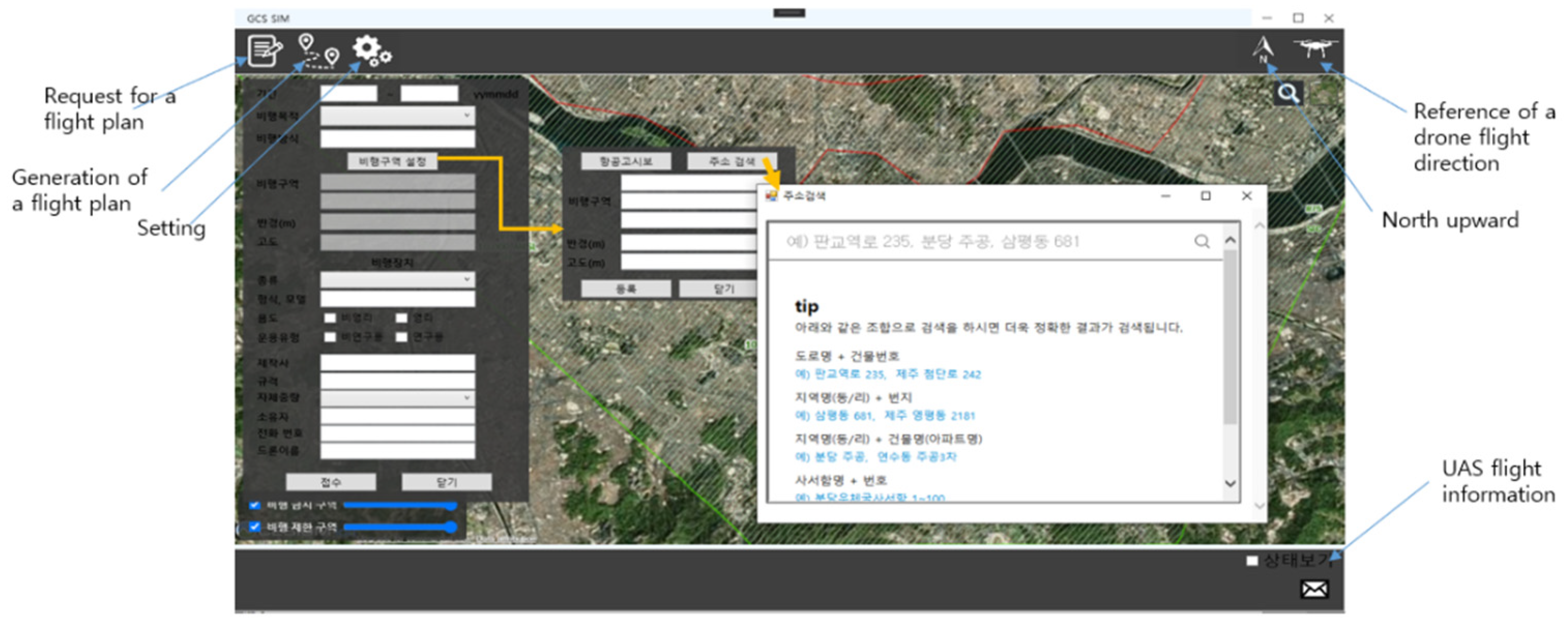
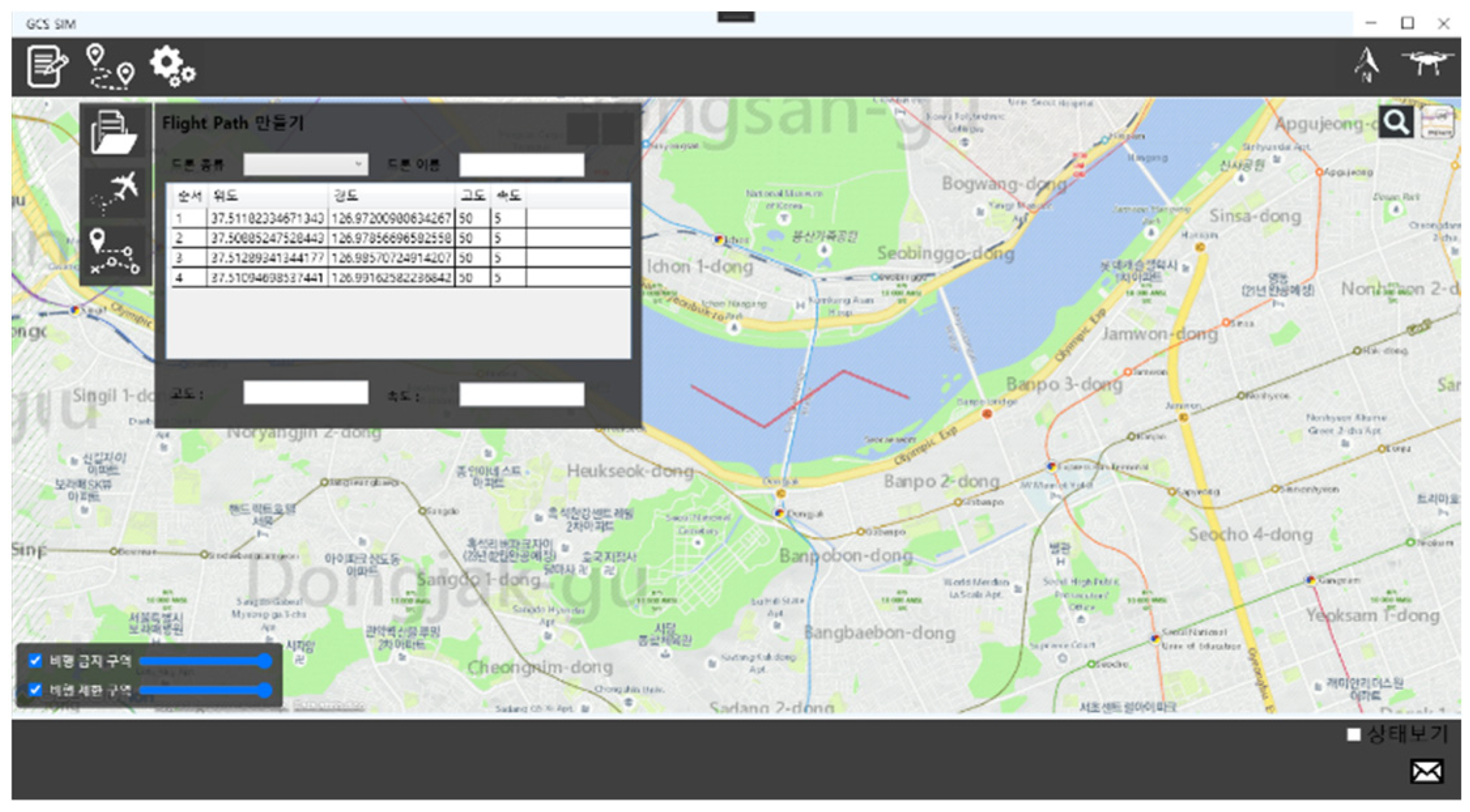
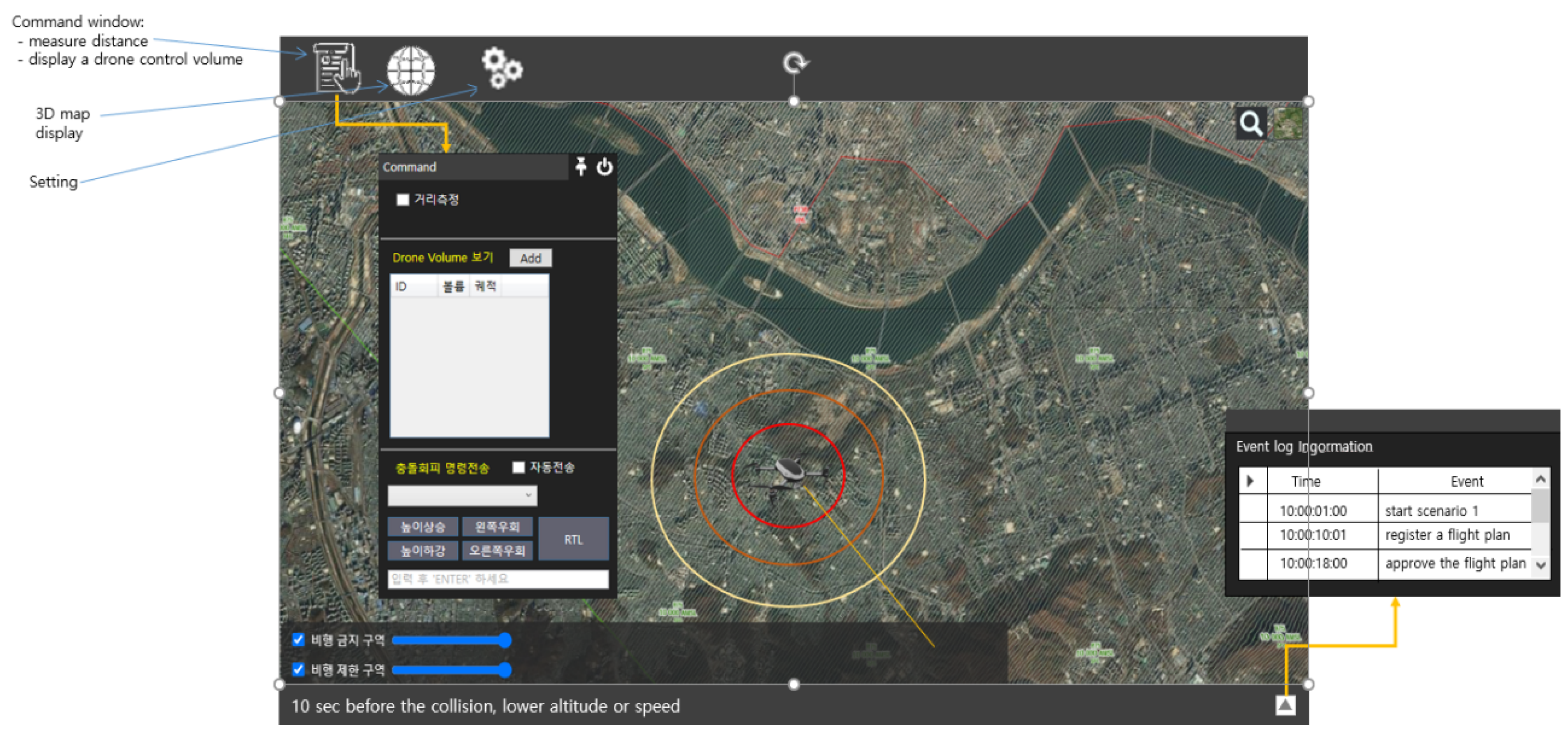
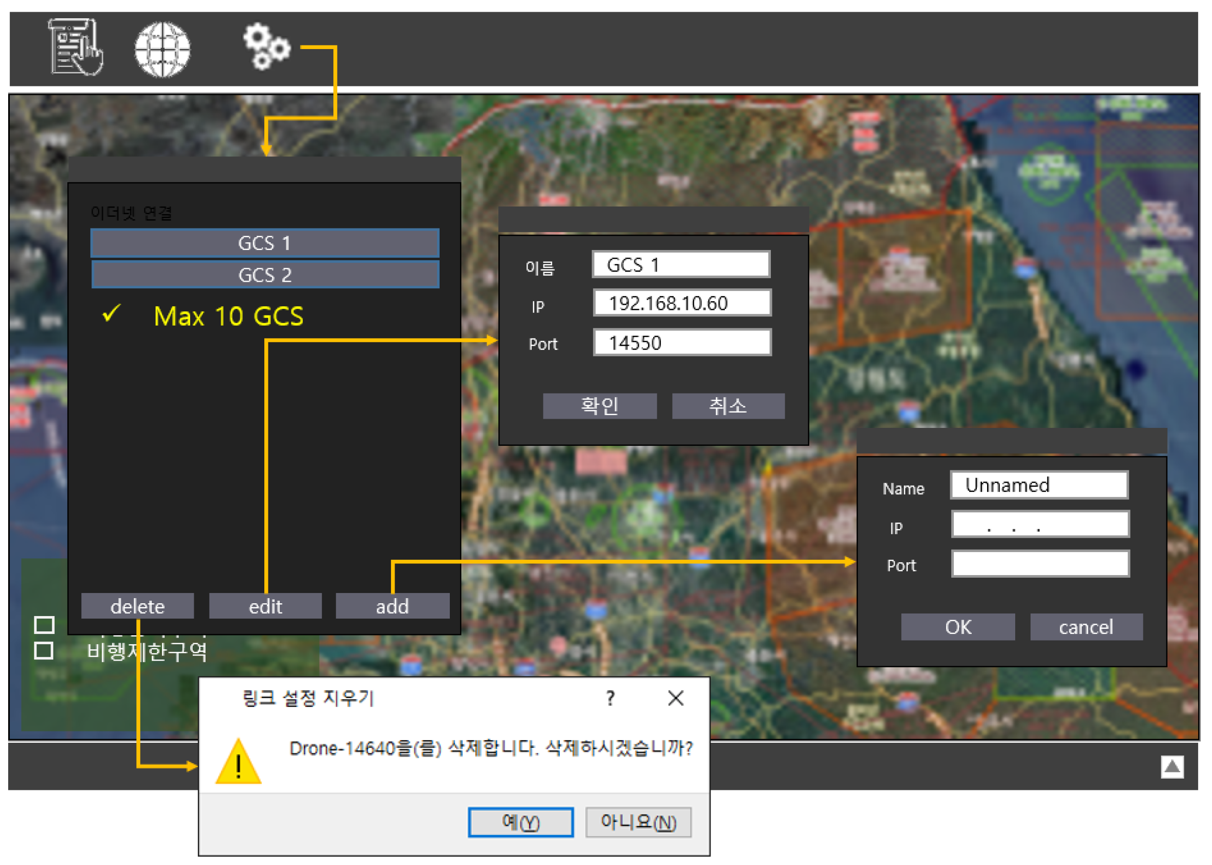
Figure 2 shows a GCS UI (User Interface), requesting a flight plan. UI is designed based on the rule dictated by KRPASA [20], where information of airspace notice and addresses along with latitudes and longitudes in the designated flight zone can be identified. Figure 3 includes a GCS UI for generation of a flight plan. Waypoints are generated by clicking on the map, and a flight path is composed out of the waypoints. Real-time edition of UAS speeds can be made during the flight. The button “start flight” is clicked to start the flight. Figure 4 has a UOS UI for registration of a flight plan. UOS releases a flight code to the GCS if the plan is approved. If it is not approved, then a message of relevant reasons is delivered to the GCS. Figure 5 shows a simulation control window of UOS. Airspace information is released to a GCS. Operation scenarios can be set such as collision of two UASs by unexpected appearance of a non-registered UAS, geofence collision, etc. In Figure 6, UTM UI is the UAS control window. The control volume of a UAS can be identified in the control window. Command messages of deconfliction maneuver and return flight can be issued for a relevant UAS. Figure 7 includes a GCS connect window. Up to 10 GCSs can be connected. A port and an ip (Internet Protocol) address are assigned to each GCS, which can be edited through the GCS connect window. Each GCS can generate up to nine UASs, among which one UAS is fully controlled either manually or by autopilot, and the remaining eight UASs fly along preassigned routes.
5. Integration Issues to Be Resolved
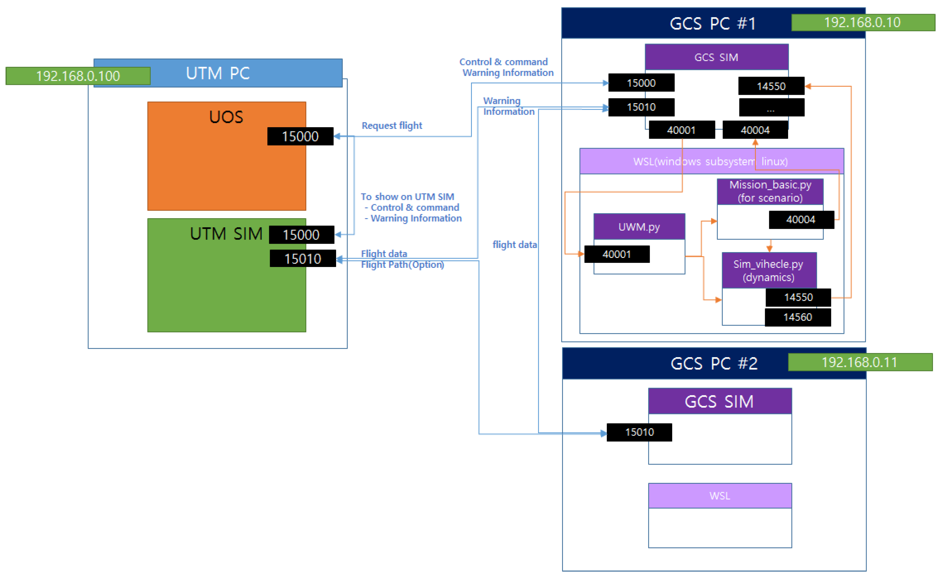
It is imperative to resolve the integration issues in order to develop simulation SW based on open sources and platforms. Most issues are caused by different languages and drivers supporting individual sources or platforms. Drone dynamics and autopilot are based on ArduPilot and MavProxy, which use Python. For real-time simulation of physics, Linux virtual machine in Windows comprises ArduPilot and MavProxy rather than using Windows’ own operation environment. For 2D and 3D visualization of maps, airspace information and graphic UAS models from GIS platforms of VWorld and Cesium are streamed and integrated in real time, which uses HTML in Java script. Graphic user interfaces of eUTM simulator are programmed in C#, and the component modules of the UTM simulator are written in C or C++, which are compiled into DLL format. Unfortunately, the Linux virtual machine does not support USB joystick inputs. Thus, some drivers and adaptors have to also be developed in order to integrate the whole system. Some of such efforts are elaborated as follows:
- ❖
- WSL (Windows Subsystem Linux):
- Communication between real-time dynamics in MavProxy on Linux (virtual machine) and Windows operation program (wpf);
- Dynamic joystick control inputs via wpf to Linux since the virtual machine does not support a USB driver;
- Interoperation between ArduPilot (providing drone physics) and Drone_Kit_Python (ArduPilot-based open source program).
- ❖
- Cesium:
- Communication between Windows operation program (wpf) and Cesium by BindObjectAsync (html to wpf) and web socket (wpf to html);
- Asynchronous generation, editing, and deletion of UAS graphic objects and flight paths;
- Display of realistic UAS objects of Glb format, including rotating rotors, in Cesium 2D and 3D maps;
- Application of VWorld’s national airspace information via wms in http to Cesium 2D and 3D maps;
- Generation of weather effects such as snow and rain, using Cesium particle system.
- ❖
- Additional Efforts:
- Address search function using a commercial portal service (Daum.net) for friendly generation of waypoints;
- Generation of waypoint files;
- Database management of log information using sqlite.
6. Deconfliction Algorithms
Barfield’s Algorithm [19] is considered in eUTM as a basic collision avoidance algorithm on UASs. The structure divides the avoidance into two spheres, namely deconfliction and avoidance spheres (Figure 10, Table 1 and Table 2). In the deconfliction sphere, an aircraft could avoid an obstacle while still maintaining its original path and a UAS should solely escape as fast as possible while in the avoidance sphere. Other deconfliction algorithms such as ORCA (Optimal Reciprocal Collision Avoidance) and adapted ORCA [21] can also be integrated and tested in the eUTM platform.
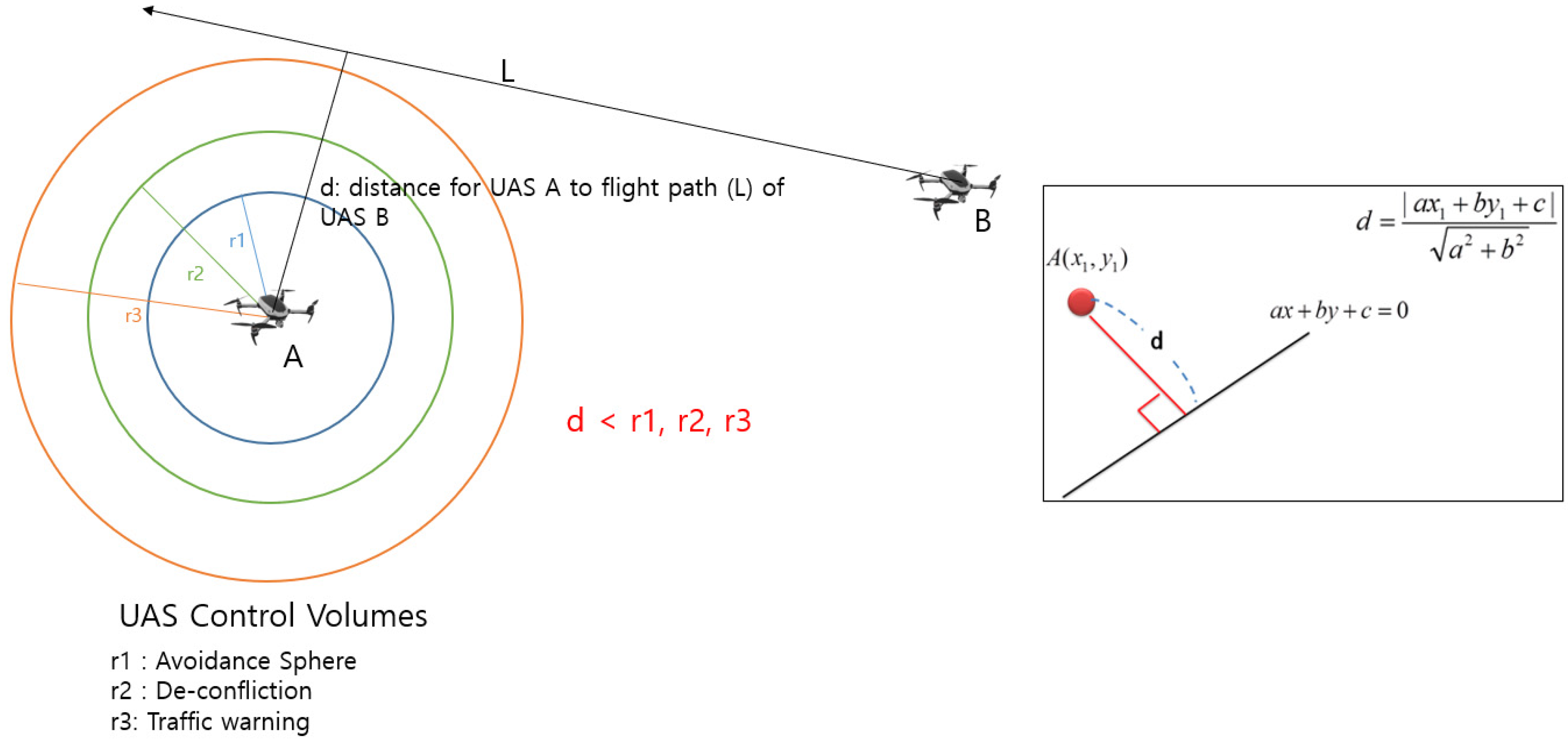
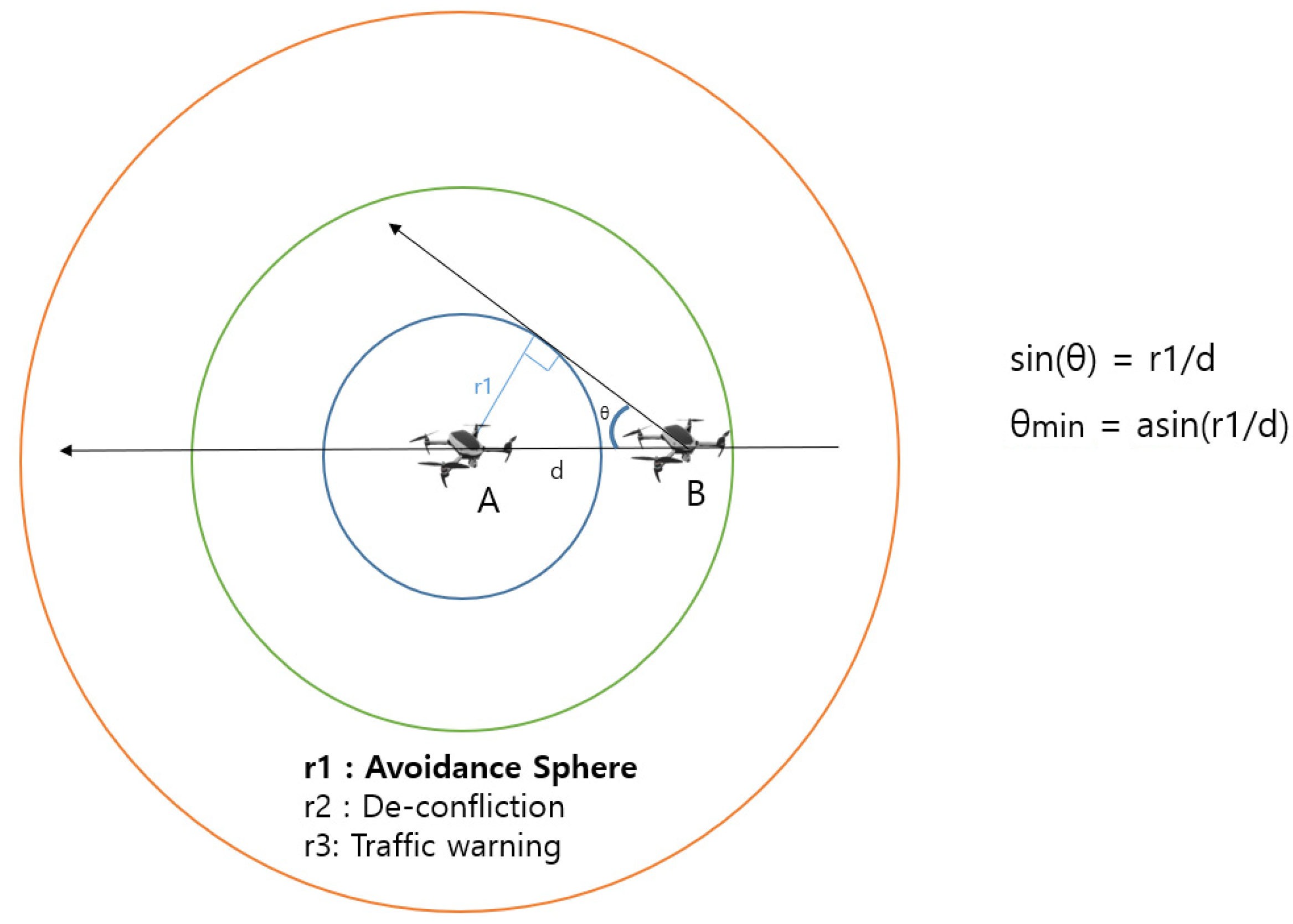
In order to determine the minimum turning angle of a UAS, which is predicted to have a potential conflict with another UAS, the simple 2D analysis is made. According to the suggestion of Barfield, three circles or spheres around UAS A are determined with radii r1, r2, and r3, which are for avoidance, deconfliction, and traffic warning, respectively. First, the distance, d, from UAS A to expected flight path (L) of UAS B is determined as in Figure 11. Then the minimum turning angle of UAS B is determined as in Figure 12.
7. Test Simulations
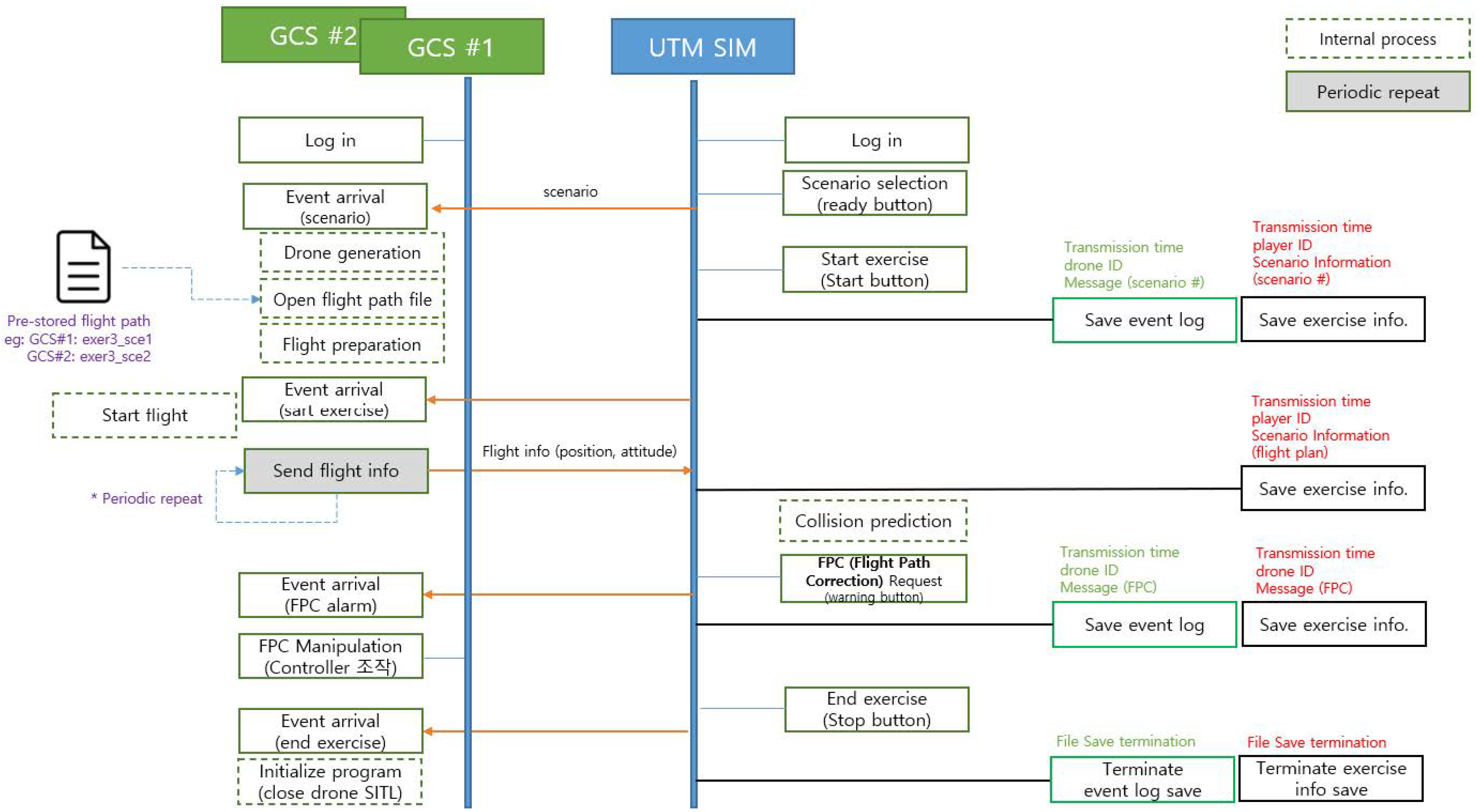
7.1. Simulation Scenarios
Now the simulation scenarios are set to support studies regarding pre-flight process, deconfliction study by time and altitude, emergency by unexpected UAS flights, and geofence avoidance. The test scenarios are expandable to comprise additional situations, which are identified to be considered later in Figure 13, Figure 14, Figure 15 and Figure 16.
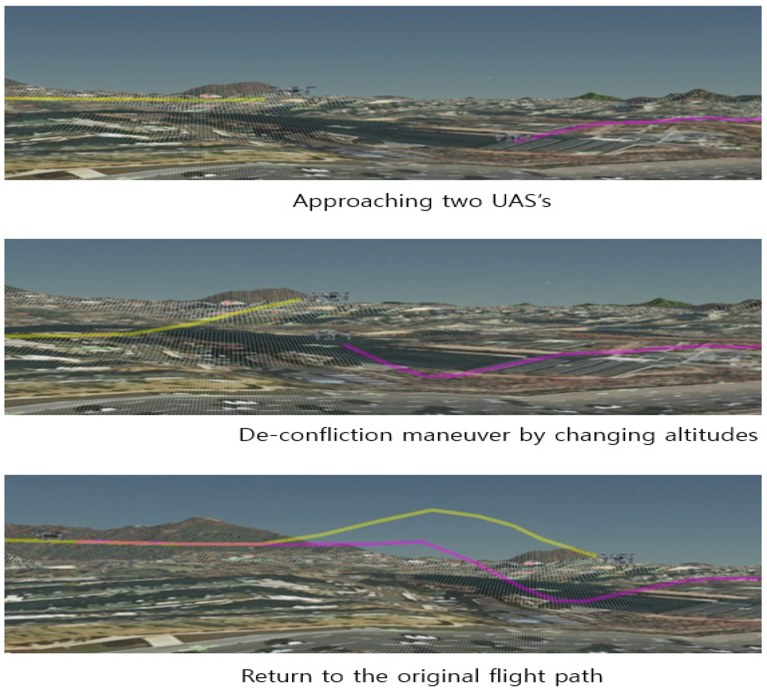
7.2. Simulation Results (DeConfliction)
Firstly, Scenario #2 in Figure 14 is tested. For demonstration, the altitude of Drone A is changed while Drone B maintains the altitude. UTM identifies the potential collision between two drones, then sends a warning message to Drone A. The GCS of Drone A changes the mode from autopilot to manual control. After completing deconfliction by ascending Drone A, the GCS returns to the autopilot mode and appropriate waypoints on the original planned flight path as in Figure 17.
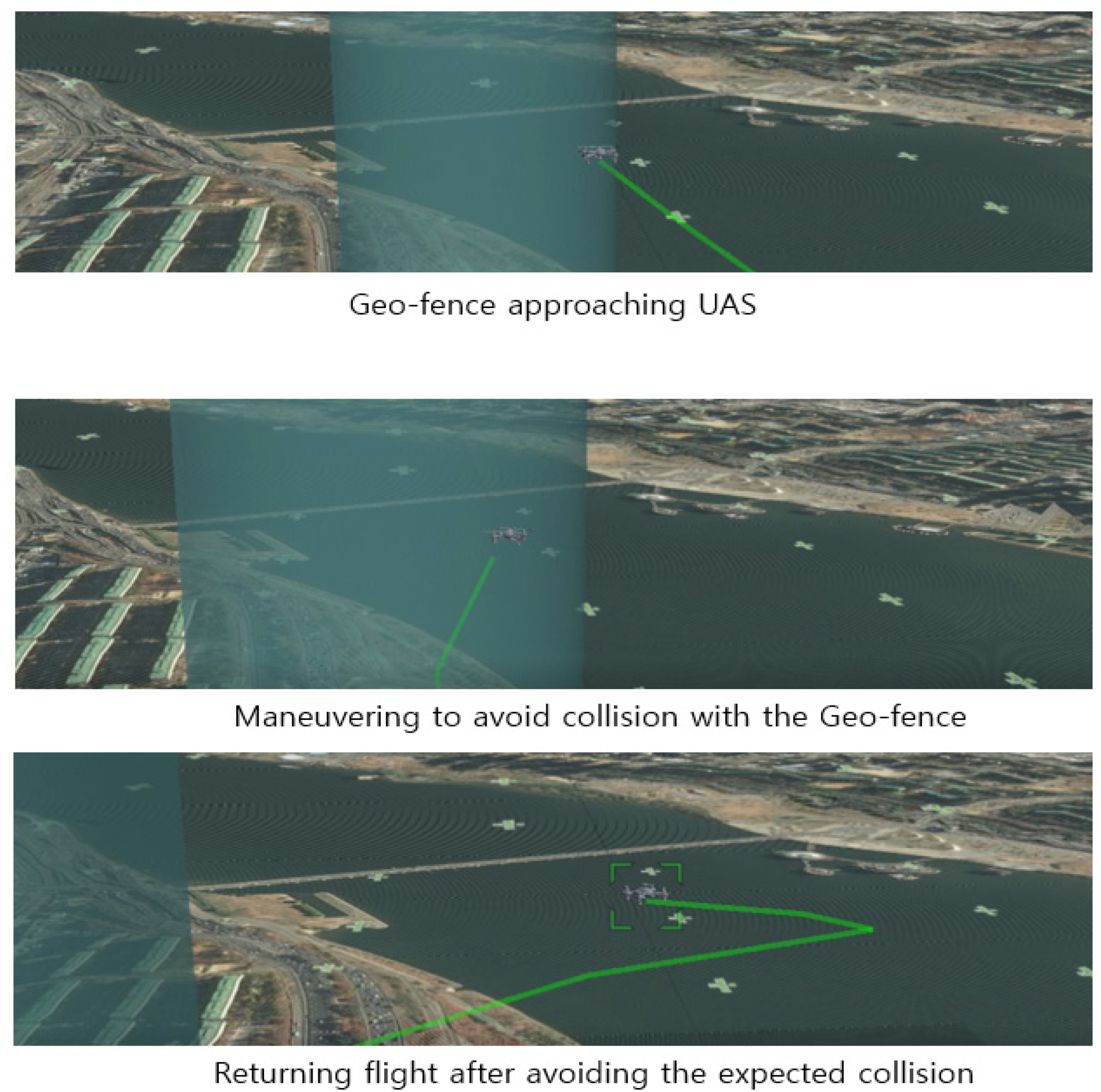
Secondly, Scenario #4 in Figure 16 is tested. UTM identifies the potential collision of the UAS with the geofence, and then sends a warning message to the UAS. The GCS changes the mode from autopilot to manual control. After completing deconfliction by changing the yaw angle while maintaining the altitude, the GCS returns to the autopilot mode and appropriate waypoints on the original planned flight path as in Figure 18.
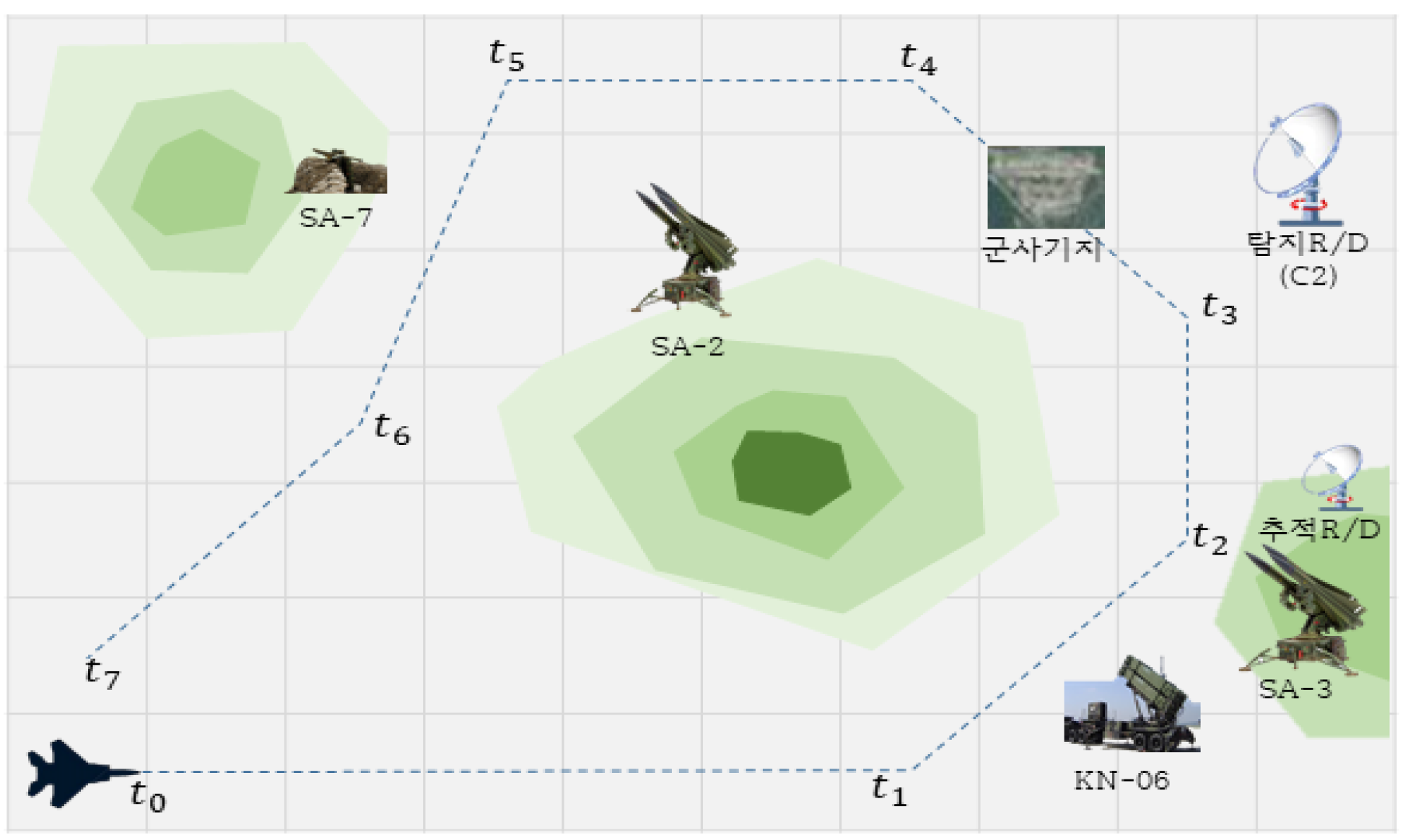
7.3. Aerial EW Application
The GCS of eUTM can also be used for aerial EW studies. In the EW simulation, a UAS flies along waypoints generated by the GCS in the presence of threats such as missiles and radars. Figure 19 illustrates the flight path generated by eUTM.
8. Conclusions
Design requirements of eUTM simulator such as flexibility and expandability are satisfied. The eUTM simulator is modularly designed to accommodate new deconfliction algorithms, registration procedures, and relevant regulations. More complicated operation scenarios can be generated by GCS’s control of preassigned UASs in addition to their own UASs. These satisfy the design requirements of flexibility and expandability. The prototype of eUTM simulator can support some UTM services up to TCL 4 or U4, which can be used to study relevant policies, regulations, deconfliction algorithm, and so on. Some drivers and adaptors are developed in order to integrate the independent sources and platforms such as ArduPilot, MavProxy, Cesium, VWorld, and Linux virtual machine. As a result, eUTM simulator composed of UOS, UTM, and GCS is developed based on open sources and platforms. By adopting ArduPilot and MavProxy, minimum differences lie between real and virtual UTM systems, which implies that simulation results can be applicable to the real world without much discrepancy. Cesium allows universal and realistic 3D visualization of a UTM geoenvironment, not limited to South Korea. VWorld provides information of national airspace of Korea, which cannot be obtained from international geoservices. As a result, a universal UTM simulator has been developed for Korean UTM environment, which can be expanded to other countries, replacing VWorld by other platforms providing relevant air space information. The eUTM simulator uses SW, not designed only for simulation, but for real drone systems. That is, eUTM can be easily converted to a real UTM simulator by changing simulated drones to actual ones. A real GCS can also be realized, replacing drone physics by a real drone system. Of course, the communication among the SW components has to be changed to the real ones in order to realize the actual UTM system.
In order to fulfill the UTM requirements up to TCL 4 or U4, more operation scenarios and deconfliction algorithms need to be included. The present system configuration also needs to be expanded to comprise more GCSs. In order to accommodate sensor-based deconfliction algorithms, inclusion of sensor models is also needed in the future enhancement. There are additional issues to be considered, including boundary management, communication failure, and dynamic airspace configuration, such as dynamic geofences. The eUTM simulator shall be ultimately enhanced to handle integrated air spaces with both manned and unmanned flights.
Author Contributions
Conceptualization, S.Y.; methodology, S.Y.; software, S.Y.; validation, D.S., Y.C. and K.P.; formal analysis, S.Y.; investigation, S.Y.; resources, D.S.; data curation, K.P.; writing—original draft preparation, S.Y.; writing—review and editing, S.Y.; visualization, S.Y.; supervision, Y.C.; project administration, K.P.; funding acquisition, D.S. All authors have read and agreed to the published version of the manuscript.
Funding
This research was funded by LIGNex1, grant 2019101.
Acknowledgments
This work was supported by Agency for Defense Development, Republic of Korea, under the contract “Modelling and Simulation Based Design and Analysis Technologies for Electronic Warfare Systems”.
Conflicts of Interest
The authors declare no conflict of interest.
References
- Federal Aviation Administration. NexGen UTM Concept of Operation, V2; Federal Aviation Administration: Washington, DC, USA, March 2020.
- CORUS Consortium. U-Space Concept of Operations, Edition 03.00.02; SESAR Joint Undertaking, October 2019. [Google Scholar]
- Available online: https://rpas-regulations.com/wp-content/uploads/2018/06/1.2-Day1_0910-1010_CAAC-SRI_Zhang-Jianping_UOMS-_EN.pdf (accessed on 8 April 2021).
- Available online: https://jutm.org/en/ (accessed on 8 April 2021).
- Zhao, Z.; Luo, C.; Zhao, J.; Qiu, Q.; Gursoy, M.C.; Caicedo, C.; Basti, F. A Simulation Framework for Fast Design Space Exploration of Unmanned Air System Traffic Management Policies. In Proceedings of the 2019 Integrated Communications, Navigation and Surveillance Conference (ICNS), Herndon, VA, USA, 9–11 April 2019. [Google Scholar]
- Homola, J.; Prevot, T.; Mercer, J.; Bienert, N.; Gabriel, C. UAS Traffic Management (UTM) Simulation Capabilities and Laboratory Environment. In Proceedings of the 35th Digital Avionics Systems Conference (DASC), Sacramento, CA, USA, 25–29 September 2016. [Google Scholar]
- Millan-Romera, J.A.; Acevedo, J.J.; Castaño, Á.R.; Perez-Leon, H.; Capitán, C.; Ollero, A. A UTM simulator based on ROS and Gazebo. In Proceedings of the 2019 Workshop on Research, Education and Development of Unmanned Aerial Systems (RED UAS), Cranfield, UK, 25–27 November 2019. [Google Scholar]
- McCarthy, T.; Pforte, L.; Burke, R. Fundamental Elements of an Urban UTM. Aerospace 2020, 7, 85. [Google Scholar] [CrossRef]
- Hentati, A.I.; Krichen, L.; Fourati, M.; Fourati, L.C. Simulation Tools, Environments and Frameworksfor UAV Systems Performance Analysis. In Proceedings of the 14th International Wireless Communications & Mobile Computing Conference, Limassol, Cyprus, 25–29 June 2018; pp. 1495–1500. [Google Scholar]
- Gazebo Components. Available online: http://gazebosim.org/tutorials?tut=components&cat=get_started (accessed on 8 April 2021).
- Pixhawk 4. Available online: https://docs.px4.io/v1.9.0/en/flight_controller/pixhawk4.html (accessed on 8 April 2021).
- Core Components. Available online: https://www.ros.org/core-components/ (accessed on 8 April 2021).
- Mission Planner Ground Control Station. Available online: https://ardupilot.org/planner/docs/mission-planner-ground-control-station.html (accessed on 8 April 2021).
- UTM CENTER. Available online: https://www.airmap.com/authorities/?utm_source=airmap&utm_medium=web&utm_campaign=menu_click&utm_content=utm_center_link_lg#utm-center (accessed on 8 April 2021).
- Go, J.H.; Lim, Y.H.; Kim, M.S.; Jang, I.S. A Study on the Next VWorld System Architecture: New Technology Analysis for the Optimal Architecture Design. J. Korea Spat. Inf. Soc. 2015, 23, 13–22. [Google Scholar] [CrossRef] [Green Version]
- The Cesium Platform. Available online: https://cesium.com/platform/ (accessed on 8 April 2021).
- Drone Autopilot Solutions. Available online: https://circuitcellar.com/research-design-hub/intro-to-ardupilot-and-px4-part-1/ (accessed on 8 April 2021).
- Kumar, A.; Yoon, S.; Kumar, V.R.S. Mixed Reality Simulation of High-Endurance Unmanned Aerial Vehicle with Dual-Head Electromagnetic Propulsion Devices for Earth and Other Planetary Explorations. Appl. Sci. 2020, 10, 3736. [Google Scholar] [CrossRef]
- Barfield, F. Autonomous collision avoidance: The technical requirements. In Proceedings of the IEEE 2000 National Aerospace and Electronics Conference (NAECON 2000), Dayton, OH, USA, 12 October 2000; pp. 808–813. [Google Scholar]
- Available online: https://www.krpasa.or.kr/p_base.php?action=main (accessed on 8 April 2021).
- Ho, F.; Geraldes, R.; Goncalves, A.; Cavazza, M.; Prendinger, H. Improved Conflict Detection and Resolution for Service UAVs in Shared Airspace. IEEE Trans. Veh. Technol. 2018, 68, 1231–1242. [Google Scholar] [CrossRef]
Figure 1.
Functions of eUTM (UAS Traffic Management) simulator.

Figure 2.
Graphic UI (User Interface)—GCS (Ground Control Stations).

Figure 3.
GCS UI—flight plan generation.

Figure 4.
UOS (UTM Operating System) UI—registration window of a flight plan.

Figure 5.
UOS UI—simulation control window.

Figure 6.
UTM (UAS Traffic Management) UI—UAS (Unmanned Aircraft Systems) control window.

Figure 7.
UTM UI—GCS connect window.

Figure 8.
Overall system configuration of eUTM.

Figure 9.
Communication among UOS, UTM, and GCSs.

Figure 10.
Concept of collision avoidance system structure on UAS.

Figure 11.
Conflict conditions between two UASs (UAS A and B).

Figure 12.
The minimum turning angle to avoid confliction between UASs.

Figure 13.
Scenario #1 (pre-flight process).

Figure 14.
Scenario #2 (deconfliction study by time and altitude).

Figure 15.
Scenario #3 (emergency by unexpected drone flights).

Figure 16.
Scenario #4 (geofence avoidance).

Figure 17.
Simulation of Scenario #2 (deconfliction study by altitude).

Figure 18.
Simulation of Scenario #4 (deconfliction study by altitude).

Figure 19.
Flight path of a UAS in aerial EW (Electronic Warfare) simulation.


Table 1.
UAS’s (Unmanned Aerial Systems) classifications, based on velocity.
| CAP 722 | Velocity | Velocity | Velocity | Sphere Radius | ||
|---|---|---|---|---|---|---|
| Classifications | Classifications | [km/h] | [m/s] | (In Collision with Static Object) | ||
| 1.5s | 25s | 40s | ||||
| Small UAS’s | Small Slow UAS’s | <50 | <13.89 | 20.83 | 347.22 | 555.56 |
| Small Fast UAS’s | <100 | <27.78 | 41.67 | 694.44 | 1111.11 | |
| Light UAS’s | Light UAS’s | <250 | <69.44 | 104.17 | 1736.11 | 2777.78 |
| Large UAS’s | Large Slow UAS’s | <500 | <138.89 | 208.33 | 3472.22 | 5555.56 |
| Large Fast UAS’s | >500 | >138.89 | 416.67 | 6944.44 | 11111.1 | |
Table 2.
Avoidance sphere radius for each categories encounter.
| Avoidance Sphere Radius [m] | ||||||
|---|---|---|---|---|---|---|
| Static | Small Slow | Small Fast | Light | Large Slow | Large Fast | |
| Object | UAS’s | UAS’s | UAS’s | UAS’s | UAS’s | |
| Small Slow UAS’s | 20.83 | 41.67 | 62.50 | 125.0 | 229.17 | 437.5 |
| Small Fast UAS’s | 41.67 | 62.5 | 83.33 | 145.83 | 250.0 | 458.33 |
| Light UAS’s | 104.17 | 125.00 | 145.83 | 208.33 | 312.5 | 520.83 |
| Large Slow UAS’s | 208.33 | 229.17 | 250.00 | 312.5 | 416.67 | 625.00 |
| Large Fast UAS’s | 416.67 | 437.5 | 458.33 | 520.83 | 625.00 | 833.33 |
Publisher’s Note: MDPI stays neutral with regard to jurisdictional claims in published maps and institutional affiliations. |
© 2021 by the authors. Licensee MDPI, Basel, Switzerland. This article is an open access article distributed under the terms and conditions of the Creative Commons Attribution (CC BY) license (https://creativecommons.org/licenses/by/4.0/).
Share and Cite
MDPI and ACS Style
Yoon, S.; Shin, D.; Choi, Y.; Park, K. Development of a Flexible and Expandable UTM Simulator Based on Open Sources and Platforms. Aerospace 2021, 8, 133. https://0-doi-org.brum.beds.ac.uk/10.3390/aerospace8050133
AMA Style
Yoon S, Shin D, Choi Y, Park K. Development of a Flexible and Expandable UTM Simulator Based on Open Sources and Platforms. Aerospace. 2021; 8(5):133. https://0-doi-org.brum.beds.ac.uk/10.3390/aerospace8050133
Chicago/Turabian StyleYoon, Sugjoon, Dongcho Shin, Younghoon Choi, and Kyungtae Park. 2021. "Development of a Flexible and Expandable UTM Simulator Based on Open Sources and Platforms" Aerospace 8, no. 5: 133. https://0-doi-org.brum.beds.ac.uk/10.3390/aerospace8050133
Note that from the first issue of 2016, this journal uses article numbers instead of page numbers. See further details here.