
A Gimballed Control Moment Gyroscope Cluster Design for Spacecraft Attitude Control


1
Applied Mechanics and Vibrations Laboratory, Department of Mechanical Engineering and Aeronautics, University of Patras, 26504 Patras, Greece
2
Department of Aerospace Science & Technology, National and Kapodistrian University of Athens, 34400 Athens, Greece
*
Author to whom correspondence should be addressed.
Aerospace 2021, 8(9), 273; https://0-doi-org.brum.beds.ac.uk/10.3390/aerospace8090273
Submission received: 1 June 2021
/
Revised: 13 September 2021
/
Accepted: 17 September 2021
/
Published: 21 September 2021
(This article belongs to the Special Issue Spacecraft Dynamics and Control)
Abstract
:This paper addresses the problem of singularity avoidance in a cluster of four Single-Gimbal Control Moment Gyroscopes (SGCMGs) in a pyramid configuration when used for the attitude control of a satellite by introducing a new gimballed control moment gyroscope (GCMG) cluster scheme. Four SGCMGs were used in a pyramid configuration, along with an additional small and simple stepper motor that was used to gimbal the full cluster around its vertical (z) axis. Contrary to the use of four variable-speed control moment gyroscopes (VSCMGs), where eight degrees of freedom are available for singularity avoidance, the proposed GCMG design uses only five degrees of freedom (DoFs), and a modified steering law was designed for the new setup. The proposed design offers the advantages of SGCMGs, such as a low weight, size, and reduced complexity, with the additional benefit of overcoming the internal elliptic singularities, which create a minor attitude error. A comparison with the four-VSCMG cluster was conducted through numerical simulations, and the results indicated that the GCMG design was considerably more efficient in terms of power while achieving a better gimbal configuration at the end of the simulation, which is essential when it is desired for different manoeuvres to be consecutively executed. Additionally, for a nano-satellite of a few kilograms, the results prove that it is feasible to manufacture the GCMG concept by using affordable and lightweight commercial off-the-shelf (COTS) stepper motors.
1. Introduction
Single-gimbal control moment gyroscopes (SGCMGs) have become popular actuators for satellites that have an agility requirement [1,2]. They are widely used in spacecraft control for manoeuvering and have been successfully employed for a wide range of space missions [3,4,5]. Agile satellites are highly manoeuvrable, and they enable more data to be gathered in a single pass compared to those employed with reaction/momentum wheel actuators. However, SGCMGs come with the inherent problem of singularities. Singularities occur when the system is unable to generate a torque output along a specific direction [6]. There are two types of singularities with respect to the ability to escape from the singular state through null motion [2]. Elliptic singularities cannot be escaped through null motion, whilst there is a null motion path for escaping hyperbolic singularities. However, in cases where the angular speed of the flywheel is equal for all SGCMGs in the cluster, it is not possible to re-orient a symmetric gimbal set to a non-symmetric set through null-space motion in order to get a singularity-free path. Such an action would result in a momentum change, and attitude error would be added into the system.
Several studies have focused on finding a measure of distance from singularities, and different indices have been proposed in the literature [7], with the most commonly used being the manipulability index [8]. Multiple SGCMG singularity avoidance/escape logics and methods have been proposed to date [5]. The singularity-robust inverse is the most common, but other methods, including null motion and path planning, have also been proposed [9,10,11]. In general, the method of planning the path of a manoeuvre also includes the optimisation of the initial configuration of the gimbals before the execution of the desired manoeuvre in order to enhance the performance of the system and provide a singularity-free trajectory [12,13,14]. A different path-planning technique that blends the pseudo-spectral and direct-shooting methods upon gimbal saturation and singularity constraints was presented in [15]. Energy-consumption-based path-planning techniques for double-gimbal CMGs have also been studied [16]. A global singularity-avoidance steering law was presented in [17], in which the time integral of the quadratic sum of the gimbal rates was minimised. A trajectory-planning approach was described in [18] to reduce the possibility of CMG saturation while the system followed a reference trajectory. Another novel deterministic allocation algorithm for computing the angular rates of the gimbal was also proposed in [19] instead of the well-known pseudo-inverse technique in order to keep the keep a four-CMG cluster in a roof configuration away from singularities. An optimisation technique for reconfiguring the gimbals back to their initial positions after completing the desired manoeuvre was also addressed.
The utilisation of more than one type of control moment exchange devices has also been studied. The combination of a reaction wheel with CMGs presented an enhanced performance compared to reaction wheel clusters in terms of agility, thus providing an affordable alternative to the conventional four-CMG cluster [20]. A control strategy that exploited both thrusters and reaction wheels was presented in [21]. Thrusters were used in an open-loop scheme to drive the spacecraft to a reference path, while reaction wheels were used for a closed-loop variable-structure control law to eliminate tracking errors due to thruster biases and initial condition errors. Another simultaneous actuation of thrusters and reaction wheels through a varying time-sharing logic was studied, and it was shown that it could be efficiently adopted for time-optimal manoeuvres [22]. Additionally, three tracking control laws that made use of momentum wheels and thrusters were explored in [23], while the implementation of an SGCMG along three orthogonal momentum wheels was tested on the Distributed Spacecraft Attitude Control System Simulator and showed promising results [24].
While a CMG cluster can easily encounter singularities, a variable-speed CMG (VSCMG) cluster deals with this problem efficiently [25]. It uses four extra degrees of freedom (DoF) compared to the SGCMG cluster by changing the angular velocity of each flywheel independently. This way, a VSCMG cluster is capable of behaving as a reaction wheel cluster near a singularity and as a conventional CMG cluster away from it [26]. Power management capabilities have also been studied for VSCMGs [27,28,29,30], whilst a novel approach of combining a double-gimbal CMG and a VSCMG was presented in [31,32]. Similarly to VSCMGs, the proposed model described in this paper makes use of more than four DoFs. The extra DoF is implemented by adding a simple, miniature, and inexpensive low-power stepper motor in order to gimbal the full SGCMG cluster. Advances in small-motor mechatronics, avionics, and pin-pullers have enabled the miniaturisation of motors by a significant amount, thus creating space for small and compact VSCMG clusters [25,33]. In addition, low-power COTS stepper motors have been proven to significantly reduce CMG power compared to RW systems [34,35]. This paper analyses the ability to use a small stepper motor to gimbal a full SGCMG cluster, making this a hybrid approach by combining the elements of SGCMGs and VSCMGs without the additional complexity of a full VSCMG system. Moreover, the design explored here does not utilise actuators with low torque capabilities, such as reaction and momentum wheels, thus preserving the agility characteristics of a simple four-CMG cluster. The details of the proposed GCMG, along with the advantages and the shortcomings of the proposed method, are presented in this paper.
2. Mathematical Modeling
2.1. VSCMG Equations of Motion
The equation of motion of a rigid spacecraft deployed with four VSCMGs is described by:
where matrices contain the components of the unit direction vector of each VSCMG frame of the cluster as:
and is the spacecraft’s inertia matrix. The spin, gimbal and transverse axes are denoted by , respectively, for the Nth VSCMG. represents the angular velocity of the spacecraft expressed and derived in terms of control axes that are fixed relative to the body of the spacecraft. In this paper, the notation indicates the time derivative of . The torques can be calculated through
and
where the inertia about the spin, gimbal and transverse axis is given by and . For simplicity, these inertias are considered to be the same for all VSCMGs. Let be the gimbal angles vector for a spacecraft employed with 4 CMGs. The vectors and contain the gimbal rate, gimbal acceleration and flywheel angular velocity, respectively. The stability condition as given in [36,37] is described by:
where
To calculate the control torque , the satellite’s kinematics equation of motion is expressed in quaternion form:
where ⊙ denotes the quaternion multiplication and is the attitude quaternion. is the angular velocity vector of the satellite, , given in a quaternion form as . For the implementation of the attitude control, the control torque applied on the satellite’s body is a function of the vector part of the error quaternion and as described by the following equation:
where and are fixed gains. The error quaternion between the current attitude quaternion and a desired quaternion as:
where and are the scalar and the vector part, respectively, and expresses the conjugate quaternion of . The normalization of the quaternions is required before evaluating the . The “3-2-1” sequence is used to convert the quaternion error to the corresponding Euler angles error.
Assuming that the inertia of each VSCMG about the spin axis is much larger compared to the inertia in gimbal and transverse axis, the stability condition is
where and
Thus, the steering law in compact form is given by:
The matrix is the Jacobian matrix of the system and except for the gimbal angles, the Jacobian matrix depends on geometric characteristics of the CMGs like the skew angle. Since the Jacobian matrix is not rectangular and the inverse of the matrix cannot be calculated, several definitions have been proposed for the inverse of the Jacobian matrix . Using a weighting matrix where
and are constant gains and , the matrix is
m is a measure of the linear independence of the columns of the matrix , usually referred as manipulability index:
This way, the VSCMG cluster is capable of performing as the conventional SGCMG cluster away from the singularity but as the manipulability index value decreases, the variable speed capability is exploited. The null space motion can be added upon the given steering law, assuming that and are the vectors that contain the desired values for the gimbal angles and the flywheels’ angular velocity. The steering law is described below:
where is the identity matrix and a constant gain. The diagonal matrix is given by
where is the 4 by 4 zero matrix and the sets represent the error with respect to the desired values as
The and values are set to 1 if it is desired the system to follow the and , respectively. Otherwise, they are set to 0. The total momentum of the VSCMG cluster is calculated by the sum of the individual momentum from each VSCMG:
where s, c are the abbreviations for sin and cos, respectively. The parameter denotes the skew angle of the 4-CMG cluster in pyramid configuration and it is chosen in such a way that the momentum envelope is nearly tree-axis symmetric and spherical [6]. are given by:
2.2. GCMG Equations of Motion
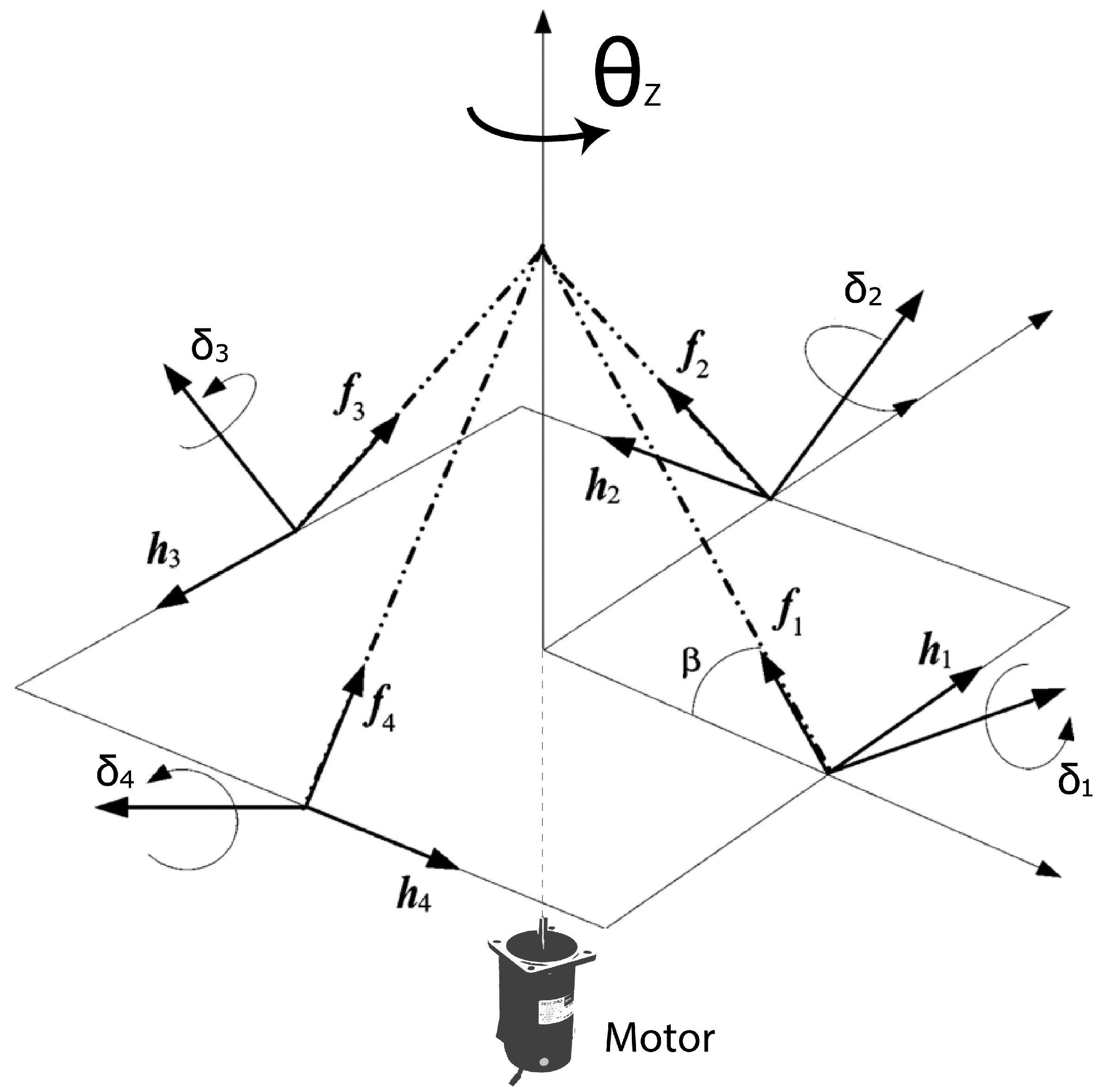
Adding an extra motor in the conventional SGCMG cluster it is possible to rotate the whole pyramid structure along the z direction, for degrees, w.r.t the body frame as shown in Figure 1. For a symmetric SGCMG cluster, its products of inertia are equal to zero and the angular momentum of the cluster, here referred as is given by Equation (32).
where is the moment of inertia about the z axis of the SGCMG cluster. The total angular momentum of the system is
Let the moment of inertia of the cluster be much smaller than this of the satellite. It applies that changing the angle negligibly affects the orientation of the satellite. As a result, the stepper motor only rotates the actuator and the rate of the total angular momentum can be calculated by:
Because the disturbance torques are neglected and the total angular momentum is preserved, Equation (34) becomes:
Let , for identical flywheels running at the same angular speed. Then,
Using the Euler formula, the Jacobian matrix of the system is formulated as:
where
The Equation (35) is given in a compact form by
The control vector is selected as
The gimbal angles as well as the rate of can be found by
where
is the standard pseudo-inverse, or commonly referred as Moore-Penrose steering law, used due to its simplicity and the real-time implementation it offers. To guarantee the attitude stability of the spacecraft, consider the following the candidate Lyapunov function [38,39,40]
The first time derivative of V is given by
Because , where is the skew matrix of , the Equation (49) becomes
Note that . Finally,
and the global stability is guaranteed for [41].
The redundancy of the system allows to exploit motion in the null space and Equation (42) can be modified to contain the null motion term as
where is a constant gain. is a diagonal matrix the values of which denote which elements of are selected for the null motion. The possible values of each element of are 0 and 1 and is given by
Linearized Model
Using the Equations (17) and (42), the input vector can be calculated by
which can be embedded in the Equation (40) resulting in
where because for simplicity. Then, the closed loop system is described by the Equation (56) and the reduced kinematics equation
Let the spacecraft’s products of inertia be zero for simplicity, i.e., , in accordance to the simulation parameters presented in Section 3. Defining the state vector , the linearization of the nonlinear model results in
where are defined by
For the set point , the Equation (58) becomes
The eigenvalues of are
The asymptotic stability is guaranteed for the parameters presented in Section 3 since every eigenvalue of has a negative real part.
3. Singularities—Preliminaries
As initially stated, the main problem when SGCMGs are utilized for spacecraft attitude control, is singularities. A brief overview of the singularities is presented, in order to better explain the selected task as presented in the next section. Near a singularity, the SGCMG cluster is incapable of producing torque along at least one direction and due to the ill-conditioned/singular Jacobian of the system in this state, the gimbal rates approach infinity. Even though it is known that only three SGCMG are necessary for three-axis control, the utilization of a redundant SGCMG provides the opportunity to avoid some types of singularities, increasing the momentum and the torque capacity of the cluster in a mass-efficient way.
Not all singularities are of the same type. They are divided into two categories. If a singular state can be escaped by null motion, it is passable or hyperbolic. Otherwise, the singularity is elliptic. The null motion of a SGCMG cluster is defined as the SGCMG gimbal motions that produce no net torque, i.e., the actuators’ generated torque does not change the attitude of the satellite. Most of the times, the null motion is exploited to avoid singularities by internally configuring the gimbal angles to better performance configurations without affecting the execution of the manoeuvre towards to commanded attitude.
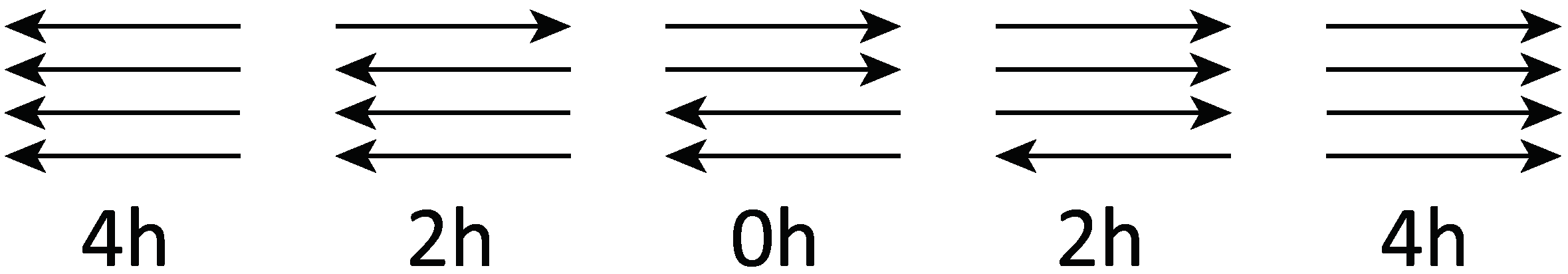
In addition, singularities are sub-categorized into external and internal. External singularities correspond to the maximum angular momentum in any single direction. Such singularities, also known as saturation singularities, are accommodated in the sizing of the control system and they are not considered for singularity avoidance. In contrast, internal singularities occur when the system is in a singularity and the cluster momentum is far from the limit of the cluster’s capability. Depending on the number of the momentum axes aligned, the singularities of a 4-SGCMG cluster are classified to 4 h, 2 h and 0 h (Figure 2).
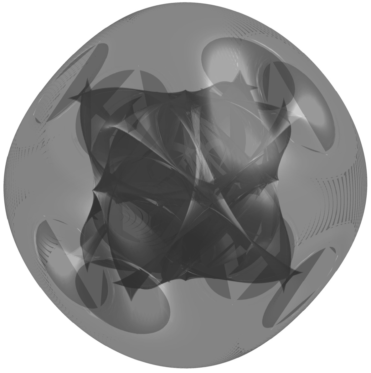
Caution must be taken when interpreting the singular surfaces since the 4 h surfaces do not always have a momentum magnitude of 4 h [6]. When two of the SGCMGs point opposite the other two, then it is a 0 h singularity. Every momentum state corresponding to a singular gimbal set is a singular surface. When these 4 h, 2 h and 0 h surfaces are plotted together, they form a continuous connection between all possible singular momentum states as illustrated in Figure 3.
The detailed understanding on the location and inner working of singularities can be found in the literature [2,11,12,39,42,43,44] as it is not the main focus of the work presented. However, the mathematical framework for examining the null motion as well as for determining the singularity types is extensively detailed in [6,42,45,46,47] and is briefly presented below for the typical 4-SGCMG pyramid cluster.
The null motion condition for the null motion momentum vector is defined by
where is the total angular momentum of the 4-SGCMG cluster and N corresponds to the Nth SGCMG of the cluster. Using the Taylor series, the null motion momentum vector can be expanded to
where and are the null motion gimbal angle displacements. The first-order necessary condition for null motion is
where and is the Jacobian matrix of the system. The null vector is the null-space vector of that is, and . In order to define the type of a singular state, let the null motion constraint
which is an alternative form of Equation (65). Let be an arbitrary vector. The inner product of with results in
Since when is along the singular direction, it applies that
where . Keeping only the second-order terms, the Equation (70) becomes
where When is a sign-definite matrix, the only solution to Equation (73) is , and there is not null motion. The null motion of gimbal angles can be described by the first-order condition
where and is the Nth weighting coefficient. are the null-space basis vectors of the Jacobian matrix
such that or From Equations (73) and (74), it applies that
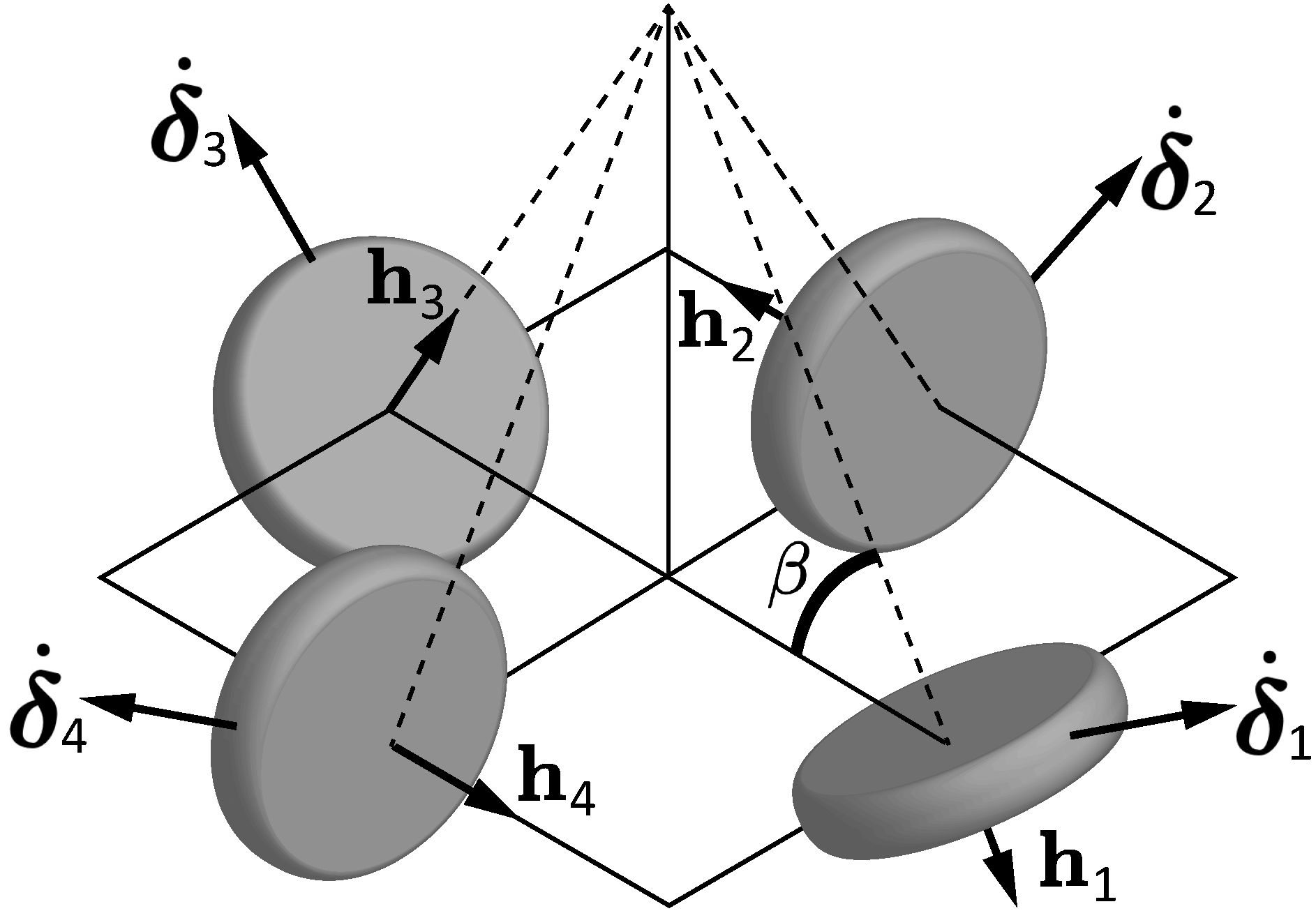
where . If matrix is sign-definite, then the singularity is elliptic and null motion is not possible. Otherwise, the singularity is hyperbolic and it is possible to exploit null motion to escape the singular state. For the 4-SGCMG cluster in pyramid configuration, it is easy to prove that the system is in an elliptic singular state when the gimbal configuration is deg as follows
The matrix is sign-definite because it has a positive determinant. Thus, the gimbal configuration is deg corresponds to an elliptic singularity. A visualization of the gimbals in this state is presented in Figure 4.
In terms of controllability, a singularity can also be examined considering the dynamics equation
and the Equation (57) where the state vector is defined as and . Without loss of generality, let for simplicity. Then, for the set point and , the open loop system can be described in the linearized form of where
Then, the controllability matrix can be calculated by
and the indicates whether the system is controllable or not. E.g., at the configuration deg, the and the system is fully controllable in this state. In contrast, the well-known elliptic singularity at deg results in indicating the uncontrollability at the certain gimbal configuration.
4. Simulation Set-Up
Following the description of the singular states and the problems they introduce to the spacecraft attitude control, it is evident that exploring the behaviour of a system employed with SGCMGs near these states is essential. Thus, the task selected to study the behaviour of each model near an internal elliptic singularity is a manoeuvre about the roll axis by −90 deg because the system encounters the deg singularity [46]. The initial non-zero gimbal configuration near the singular configuration is selected to guarantee that the system will meet the singularity while the initial attitude quaternion is . Similar to [12,34,48], studying this type of singular state in addition to the initial gimbal values that are extremely near the singularity is a useful simulation strategy which enables to prove that the proposed GCMG design is effective even in challenging conditions. The total simulation time is 20 s. The first 2 s the systems is at rest, then the system is commanded to follow the desired orientation given by the quaternion . Since the simulation describes a discrete time system, it is required to integrate the quaternion rate at the ith iteration as given by Equation (16) using the equation:
where is the time between two consecutive iterations. The SGCMG rates are saturated when they exceed the specific threshold , using the following formula:
It is preferred to saturate the gimbal angle rates using Equation (87) over applying a boundary value to every gimbal angle rate that exceeds the required threshold because the characteristics of the motion are conserved. For a fair comparison, it is desired to keep the number of the unrestricted DoF of the two models the same. Thus, every DoF apart from the motion of the four gimbals in the cluster is selected to follow certain criteria, i.e., every flywheel of the VSCMG cluster as well as the stepper motor of the GCMG cluster are used for null space motion following a preferred value. Moreover, the rotation angle and rate of the stepper motor are limited in order to better depict a real-life application.
5. Simulation Results
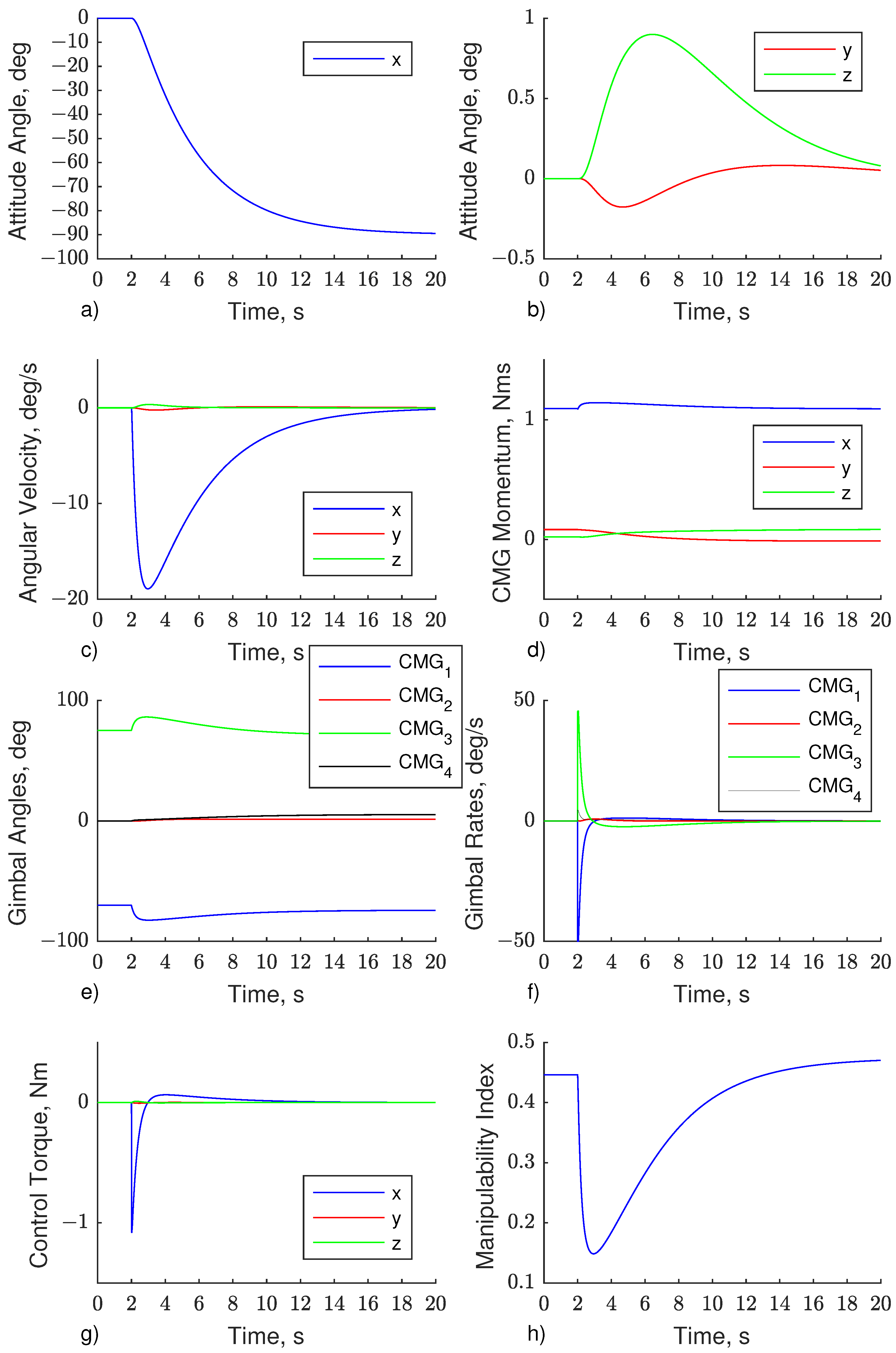
Figure 5 illustrates the results derived by using the VSCMG cluster in avoiding the singularity encountered. The steering law of Equation (26) is applied and the null motion guides the system to follow only the desired set because the equals zero.
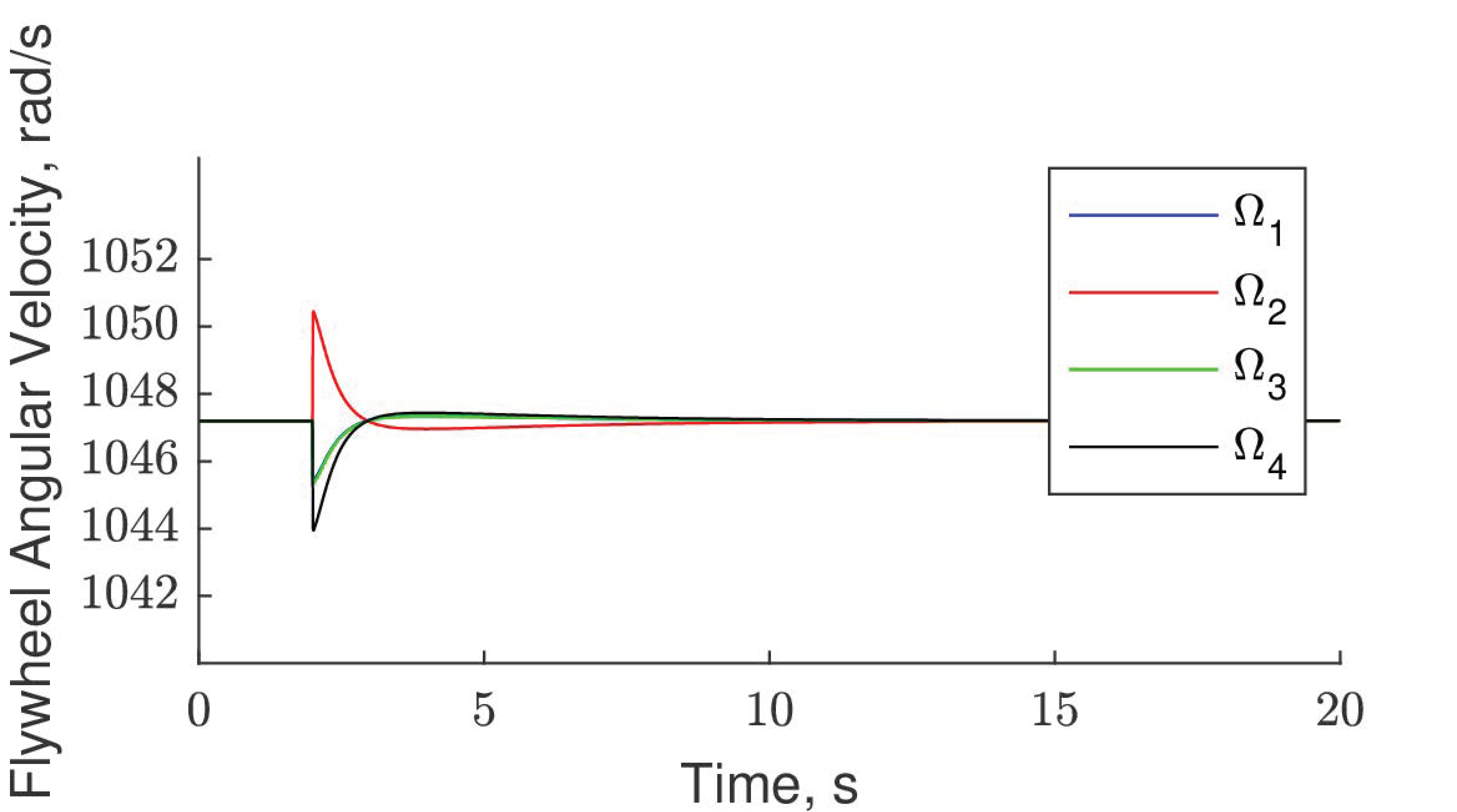
The attitude angle in x axis is shown in Figure 5a. After t = 2 s the attitude begins to follow the commanded quaternion. The system reaches the steady state at approximately t = 18 s where the attitude error about the roll axis is slightly less than 1 deg. Figure 5b shows that the manoeuvre is executed with a minor attitude error about the pitch and yaw axis because the the system exploits the variable speed part to handle the approach to singularity. In particular, the maximum deviation of the attitude angle about pitch and yaw is −0.18 deg and 0.9 deg, respectively. The angular velocity of the satellite is presented in Figure 5c and the maximum absolute value is 18.9 deg/s in the negative of the roll axis. It is possible to accomplish a lower maximum velocity value by decreasing the value of the gain . The momentum profile of the VSCMG cluster, is presented in Figure 5d. The momentum in x direction increases approaching the value of 1.15 Nms where the gimbals are in singular configuration [47]. Figure 5e shows that the angle of the first and the third gimbal is heading towards −90 deg and +90 deg, respectively, when the system approaches the singularity but in the steady state these values change to −74.3 deg and 71.1 deg. The rest of the gimbal angles remain almost zero through the whole simulation time. Figure 5f presents the gimbal rates. It is observed that mainly the first and the third gimbal contribute to the rotation whilst the rest gimbal angle rates are significantly lower. The rate of the first gimbal reaches the saturation for a slight period of time but in the steady state, no rates are generated by the steering law. The control torque as presented in Figure 5g is about the roll axis. From t = 2 s to t = 2.9 s the torque spans to the negative of roll axis but after t = 2.9 s the sign changes to decelerate the satellite until the steady state. The manipulability index drops from 0.446 (t = 0 s) to 0.149 (t = 2.9 s). It is known that the minimum value is obtained once the system reaches closer to the singular configuration. After that, the index increases till the steady state where the obtain value is equal to 0.47 (Figure 5h). The angular velocity of each flywheel in the cluster is presented in Figure 6. A small change in the angular velocity of each flywheels is capable of solving the singularity problem. The maximum deviation from the nominal velocity is 0.31% at t = 2 s but in the steady state all flywheels are following the set.
Overall, the 4-VSCMG cluster is capable of avoiding the singular state due to the redundancy in the DoF it offers. The system avoids the elliptic singularity because it is capable to change the flywheel’s angular velocity while configuring the four gimbals. When the null space motion is applied, the system can efficiently track the desired set and follow the commanded manoeuvre while maintaining a high performance configuration.
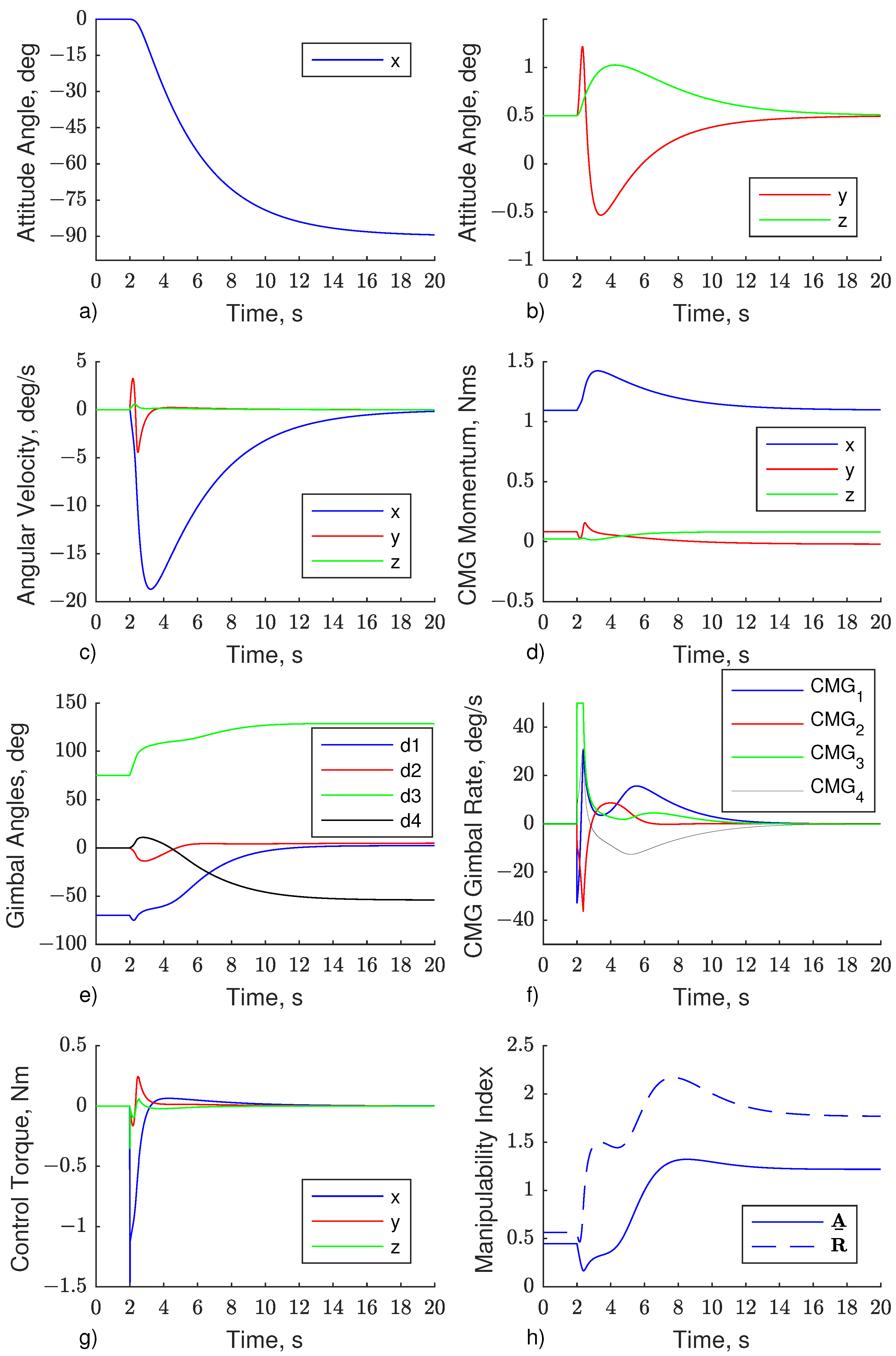
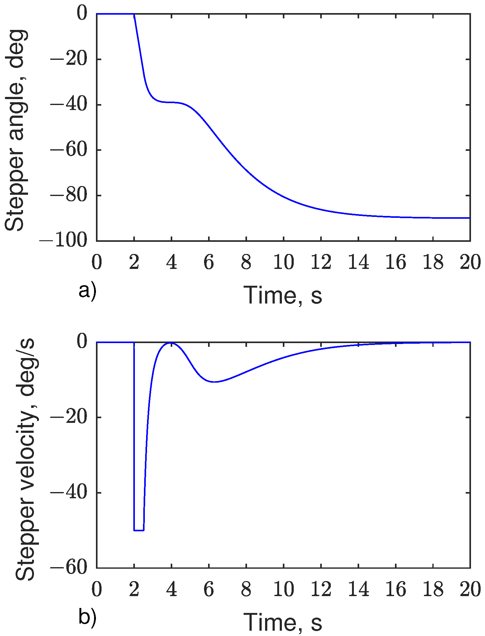
The same manoeuvre is executed using the GCMG model and the results are presented in Figure 7. Figure 7a shows that after t = 2 s the system follows the desired quaternion. The attitude angle about x direction is starting to decrease reaching the steady state at t = 18 s with a steady state error similar to this of the VSCMG. The GCMG exploits the fifth DoF to handle the encountering singularity completing the manoeuvre with slight attitude error (Figure 7b). Compared to the VSCMG, the maximum deviation is −1 deg and 0.53 deg about the pitch and yaw axis, respectively. This deviation is also depicted in the angular velocity of the satellite mainly in the negative of the y direction with an absolute maximum velocity of 4.4 deg/s (Figure 7c). The main velocity component is about the x axis and the maximum absolute value is 18.7 deg/s. The angular momentum of the GCMG cluster is presented in Figure 7d. When the momentum in x direction reaches the value of 1.15 Nms where is known that the system encounters the singular state, a change in the momentum about y is presented. The gimbal angles profile is shown in Figure 7e and in the steady state the gimbal angle vector is deg. The rate of the third gimbal becomes saturated from t = 2 s to t = 2.37 s (Figure 7f) while every other gimbal rate is scaled down according to Equation (87) for this time period. The control torque can be seen in Figure 7g and the profile in x direction is similar to this of the VSCMG. It spans in the negative of the axis till t = 3.2 s where the overshoot in the positive of the axis indicates again the deceleration of the satellite. It can be seen in Figure 7h that the manipulability index of the CMG cluster, i.e., use of —drops to 0.166 at t = 2.4 s but in the steady state it converges to 1.22. In contrast, the lowest value of the manipulability index of the GCMG cluster—use of —is 0.466 at t = 2.15 s. Even though the manipulability index in these two cases is not comparable because of the unequal DoF are used in each case, the profile of the index is. The significant difference is noticed from t = 2.16 s to t = 3 s. In this period of time the manipulability index of the GCMG increases quickly because of the action of the stepper motor, in contrast to this of the CMG which remains near the singularity. In Figure 8a,b the angle and rate are presented. The stepper motor rotates the cluster −90 deg following the commanded set and the rate remains saturated from t = 2 s to t = 2.5 s. Then, it decreases again because of the motion in the null space and in the steady state, it drops to zero. Table 4 presents the percentage differences for the main parameters among the two simulations.
As the results indicate, both the VSCMG and GCMG cluster are capable of avoiding the internal singularity exploiting the redundant DoF while maintaining a high manipulability index through the whole manoeuvre and similar settling time. Contrary to the results derived by using the GCMG, the maximum deviation of the attitude angle and satellite’s angular velocity is lower about pitch and higher about yaw axis, respectively, in the case of VSCMG. The same applies for the control torque. The manipulability index profile for the VSCMG is significantly different from this of the GCMG. It presents a wide dip and slowly increases until the end of the simulation. The GCMG presents a higher index value both in singularity and the steady state compared to the VSCMG. Thus, after completing the desired manoeuvre the GCMG cluster comes to a better configuration which is significant for the beginning of the next manoeuvre without re-configuring its gimbals, e.g., through null space.
No major difference is presented in the maximum absolute value of the angular velocity of the satellite about the roll axis for the two models. Both models are capable of avoiding the elliptic singular state with attitude error lower than 1 deg which makes the GCMG an efficient alternative to the VSCMG when it is desired to explicitly follow a given trajectory. The memory allocation is almost identical for the two models (approx. 2% less in the case of GCMG). The difference in execution time is less than 1% as measured by 100 consecutive measurements. However the mathematical complexity of the GCMG is highly reduced. In applications where only the final attitude is of interest while high attitude error is allowed during the manoeuvre, the extra motor of the GCMG design is adding weight and complexity without providing any extra value compared to the conventional SGCMG. Such a task can be efficiently accomplished by a SGCMG cluster combined with the modified singularity robust inverse steering law.
Caution must be taken in selecting the moment of inertia matrix of the CMG cluster. The used value is negligible compared to this of the satellite and as a result a minor rotation is applied to the system. A large CMG inertia may result in rotating the satellite in the opposite direction resulting in higher attitude errors.
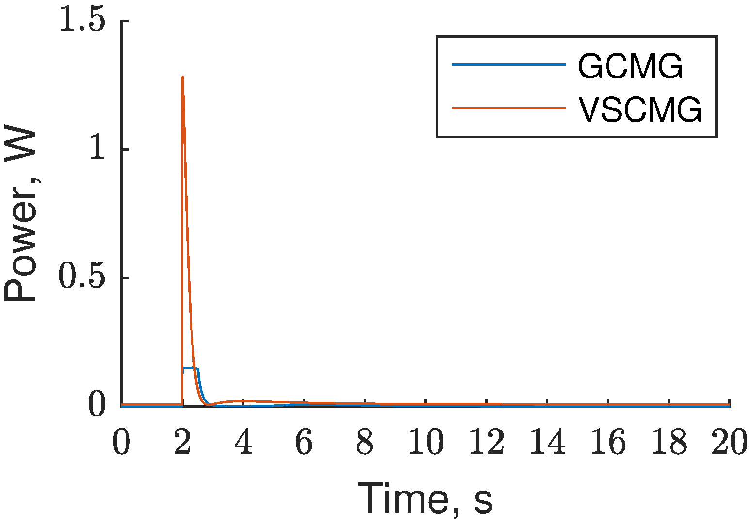
Figure 9 illustrates an important difference between the total power required by the VSCMG compared to the GCMG to execute the same manoeuvre. The power component that is related to the initial spin up and the stabilization of the flywheels to their nominal velocities is the same in both cases and as a result, it has been omitted. The power profiles presented consist of two power components. The first is related to power used for the gimbal motion whilst the second is related to the power needed to change the velocity of the flywheels and control the stepper motor in the VSCMG and GCMG design, respectively. The power difference shown in Figure 9 is mainly due to the second component because the order of magnitude of the power of the first component is much smaller. There is an 88.1% and a 74.1% decrease in the maximum and the mean power needed when the GCMG is exploited. The maximum and the mean values for both cases are presented in Table 5. The values indicate that is feasible to use a commercial off-the-shelf stepper motor to manufacture the GCMG design with a required motor torque capability of less than 0.34 Nm. Such demands can be easily fulfilled by low mass and affordable stepper motors allowing the application of the GCMG actuator to micro and nano-satellites missions.
A more detailed power comparison of COTS based CMGs using stepper motors will be presented in future work showing experimental results which as shown previously in [34,35] show the power advantage of using stepper motors for CMG systems. The proposed GCMG uses less power than a conventional VSCMG cluster as the added gimbal motor/extra degree of freedom brings savings in power compared to the increased speed/power needed when using VSCMGs.
6. Conclusions
This paper addresses the problem of singularity avoidance in a 4-single gimbal control moment gyroscope (SGCMG) cluster in pyramid configuration as used for the attitude control of a satellite. A novel SGCMG cluster design is proposed that uses an extra stepper motor capable of rotating the full cluster and a comparison is held among the design proposed and the VSCMG cluster. Both are capable of avoiding the encountering singularity even though the GCMG presents a lower and a higher attitude error about the yaw and the pitch, respectively, for the exact same tuning. However, the GCMG shows a clear advantage over the VSCMG in the gimbal configuration in the end of the manoeuvre. The gimbals end in a configuration of higher performance that is essential for agile and small satellites that perform multiple consecutive manoeuvres in one pass. Moreover, the results indicate that GCMG provides a superior performance in terms of the power needed to execute the manoeuvre while it has been shown that a simple COTS stepper motor can be utilized in practice for manufacturing the GCMG concept. With three less DoF and reduced mathematical complexity, the GCMG design may be an effective alternative to the VSCMG in applications that is desired to explicitly follow a commanded trajectory. Even though the present study only investigates the GCMG cluster using the Moore-Penrose steering law, an extensive analysis is kept for future work to understand how the GCMG behaves to different steering laws.
Author Contributions
Conceptualization, C.P.; Methodology, C.P.; Project administration, V.L. and V.K.; Supervision, V.L. and V.K.; Writing—original draft, C.P.; Writing—review and editing, C.P. All authors have read and agreed to the published version of the manuscript.
Funding
This research received no external funding.
Institutional Review Board Statement
Not applicable.
Informed Consent Statement
Not applicable.
Conflicts of Interest
The authors declare no conflict of interest.
References
- Wie, B. New Singularity Escape/Avoidance Steering Logic for Control Moment Gyro Systems. In Proceedings of the AIAA Guidance, Navigation, and Control Conference and Exhibit, Boston, MA, USA, 10–12 August 2003; American Institute of Aeronautics and Astronautics: Austin, TX, USA, 2003. [Google Scholar] [CrossRef]
- Margulies, G. Geometric Theory of Single-Gimbal Control Moment Gyro Systems. J. Astronaut. Sci. 1978, 26, 159–191. [Google Scholar]
- Roser, X.; Sghedoni, M. Control Moment Gyroscopes (CMG’s) and their Application in Future Scientific Missions. In Spacecraft Guidance, Navigation and Control Systems; Kaldeich-Schuermann, B., Ed.; European Space Agency (ESA) Special Publication: Noordwijk, The Netherlands, 1997; Volume 381, p. 523. [Google Scholar]
- Defendini, A.; Lagadec, K.; Guay, P.; Blais, T.; Griseri, G. Low Cost CMG-Based AOCS Designs. In Spacecraft Guidance, Navigation and Control Systems; Schürmann, B., Ed.; ESA Special Publication: Noordwijk, The Netherlands, 2000; Volume 425, p. 393. [Google Scholar]
- Wie, B. Space Vehicle Dynamics and Control; American Institute of Aeronautics and Astronautics: Reston, VA, USA, 2008. [Google Scholar]
- Leve, F.A.; Hamilton, B.J.; Peck, M.A. Spacecraft Momentum Control Systems; Springer International Publishing: Berlin/Heidelberg, Germany, 2015; pp. 1–247. [Google Scholar] [CrossRef]
- Patel, S.; Sobh, T. Manipulator Performance Measures—A Comprehensive Literature Survey. J. Intell. Robot. Syst. 2015, 77, 547–570. [Google Scholar] [CrossRef] [Green Version]
- Yoshikawa, T. Manipulability of Robotic Mechanisms. Int. J. Robot. Res. 1985, 4, 3–9. [Google Scholar] [CrossRef]
- Wie, B.; Bailey, D.; Heiberg, C. Singularity Robust Steering Logic for Redundant Single-Gimbal Control Moment Gyros. J. Guid. Control Dyn. 2001, 24, 865–872. [Google Scholar] [CrossRef]
- Paradiso, J. A Search-Based Approach to Steering Single Gimballed CMGs; Draper Laboratory: Cambridge, MA, USA, 1991. [Google Scholar]
- Paradiso, J. Global steering of single gimballed control moment gyroscopes using a directed search. J. Guid. Control Dyn. 1992, 15, 1236–1244. [Google Scholar] [CrossRef]
- Vadali, S.R.; Walker, S.R.; OH, H.S. Preferred gimbal angles for single gimbal control moment gyros. J. Guid. Control Dyn. 1990, 13, 1090–1095. [Google Scholar] [CrossRef]
- Geshnizjani, R.; Kornienko, A.; Ziegler, T.; Loehr, J.; Fichter, W. Optimal Initial Gimbal Angles for Agile Slew Maneuvers with Control Moment Gyroscopes. In Proceedings of the AIAA Scitech 2019 Forum, San Diego, CA, USA, 7–11 January 2019; American Institute of Aeronautics and Astronautics: Reston, VA, USA, 2019; pp. 1–10. [Google Scholar] [CrossRef]
- Nanamori, Y.; Takahashi, M. Steering law of control moment gyros using optimization of initial gimbal angles for satellite attitude control. Nihon Kikai Gakkai Ronbunshu C Hen/Trans. Jpn. Soc. Mech. Eng. Part C 2008, 74, 2698–2704. [Google Scholar] [CrossRef]
- Qian, Z.; Guojin, T. Technical Note: Space Station Zero Propellant Maneuver Path Planning Considering SGCMG Saturation and Singularity. J. Astronaut. Sci. 2014, 61, 305–318. [Google Scholar] [CrossRef]
- Cui, P.; He, J.; Cui, J.; Li, H. Improved Path Planning and Attitude Control Method for Agile Maneuver Satellite with Double-Gimbal Control Moment Gyros. Math. Probl. Eng. 2015, 2015, 878724. [Google Scholar] [CrossRef]
- Geng, Y.; Hou, Z.; Huang, S. Global Singularity Avoidance Steering Law for Single-Gimbal Control Moment Gyroscopes. J. Guid. Control Dyn. 2017, 40, 3027–3036. [Google Scholar] [CrossRef]
- Jia, Y.; Misra, A.K. Trajectory Planning for a Space Robot Actuated by Control Moment Gyroscopes. J. Guid. Control Dyn. 2018, 41, 1838–1842. [Google Scholar] [CrossRef]
- Leeghim, H.; Lee, C.Y.; Jin, J.; Kim, D. A Singularity-free Steering Law of Roof Array of Control Moment Gyros for Agile Spacecraft Maneuver. Int. J. Control. Autom. Syst. 2020, 18, 1679–1690. [Google Scholar] [CrossRef]
- Currie, B.J. Control of a Spacecraft Using Mixed Momentum Exchange Devices. Master’s Thesis, California Polytechnic State University, San Luis Obispo, CA, USA, 2014. [Google Scholar]
- Ye, D.; Sun, Z.; Wu, S. Hybrid thrusters and reaction wheels strategy for large angle rapid reorientation with high precision. Acta Astronaut. 2012, 77, 149–155. [Google Scholar] [CrossRef]
- Lee, B.H.; Lee, B.U.; Oh, H.S.; Lee, S.H.; Rhee, S.W. Time optimal attitude maneuver strategies for the agile spacecraft with reaction wheels and thrusters. J. Mech. Sci. Technol. 2005, 19, 1695–1705. [Google Scholar] [CrossRef]
- Hall, C.D.; Tsiotras, P.; Shen, H. Tracking Rigid Body Motion Using Thrusters and Momentum Wheels. J. Astronaut. Sci. 2002, 50, 311–323. [Google Scholar] [CrossRef]
- Skelton, C.E. Mixed Control Moment Gyro and Momentum Wheel Attitude Control Strategies. Master’s Thesis, Virginia Polytechnic Institute and State University, Blacksburg, VA, USA, 2003. [Google Scholar]
- Richie, D.J.; Lappas, V.J.; Palmer, P.L. Sizing/Optimization of a Small Satellite Energy Storage and Attitude Control System. J. Spacecr. Rocket. 2007, 44, 940–952. [Google Scholar] [CrossRef] [Green Version]
- Richie, D.J.; Lappas, V.J.; Asghar, S. Constrained singularity avoidance using VSCMGs for combined attitude and power tracking. In Proceedings of the 2007 European Control Conference (ECC), Kos, Greece, 2–5 July 2007; pp. 3500–3506. [Google Scholar] [CrossRef]
- Richie, D.J.; Lappas, V.J.; Prassinos, G. A practical small satellite variable-speed control moment gyroscope for combined energy storage and attitude control. Acta Astronaut. 2009, 65, 1745–1764. [Google Scholar] [CrossRef]
- Yoon, H.; Tsiotras, P. Spacecraft Adaptive Attitude and Power Tracking with Variable Speed Control Moment Gyroscopes. J. Guid. Control Dyn. 2002, 25, 1081–1090. [Google Scholar] [CrossRef] [Green Version]
- Yoshihara, H.; Takahashi, M. Optimal Power Management Considering Attitude Control and Battery Deterioration Control for Spacecraft with VSCMG/IPACS. In Proceedings of the AIAA Scitech 2020 Forum, Orlando, FL, USA, 6–10 January 2020; American Institute of Aeronautics and Astronautics: Reston, VA, 2020; pp. 1–13. [Google Scholar] [CrossRef]
- Sasaki, T.; Alcorn, J.; Schaub, H.; Shimomura, T. Convex Optimization for Power Tracking of Double-Gimbal Variable-Speed Control Moment Gyroscopes. J. Spacecr. Rocket. 2018, 55, 541–551. [Google Scholar] [CrossRef]
- Sasaki, T.; Shimomura, T.; Schaub, H. Robust Attitude Control Using a Double-Gimbal Variable-Speed Control Moment Gyroscope. J. Spacecr. Rocket. 2018, 55, 1235–1247. [Google Scholar] [CrossRef]
- Stevenson, D.; Schaub, H. Nonlinear Control Analysis of a Double-Gimbal Variable-Speed Control Moment Gyroscope. J. Guid. Control Dyn. 2012, 35, 787–793. [Google Scholar] [CrossRef]
- Gaude, A.; Lappas, V. Design and Structural Analysis of a Control Moment Gyroscope (CMG) Actuator for CubeSats. Aerospace 2020, 7, 55. [Google Scholar] [CrossRef]
- Lappas, V.J. A Control Moment Gyro (CMG) Based Attitude Control System (ACS) for Agile Small Satellites. Ph.D. Dissertation, School of Electronics and Physical Sciences, University of Surrey, Guildford, UK, 2002. [Google Scholar]
- Lappas, V.; Steyn, W.H.; Underwood, C. Design and Testing of a Control Moment Gyroscope Cluster for Small Satellites. J. Spacecr. Rocket. 2005, 42, 729–739. [Google Scholar] [CrossRef]
- Schaub, H.; Junkins, J. CMG singularity avoidance using VSCMG null motion. In Proceedings of the AIAA/AAS Astrodynamics Specialist Conference and Exhibit, Boston, MA, USA, 10–12 August 1998; American Institute of Aeronautics and Astronautics: Reston, VA, USA, 1998. [Google Scholar] [CrossRef]
- Schaub, H.; Vadali, S.R.; Junkins, J.L. Feedback Control Law for Variable Speed Control Moment Gyros. J. Astronaut. Sci. 1998, 46, 307–328. [Google Scholar] [CrossRef]
- Wie, B.; Weiss, H.; Arapostathis, A. Quarternion feedback regulator for spacecraft eigenaxis rotations. J. Guid. Control Dyn. 1989, 12, 375–380. [Google Scholar] [CrossRef]
- Junkins, J.L.; Schaub, H. Analytical Mechanics of Space Systems, 2nd ed.; American Institute of Aeronautics and Astronautics: Reston, VA, USA, 2009. [Google Scholar] [CrossRef]
- Xue-qin, C.; Yun-hai, G.; Yu-hai, M.; Feng, W.; Xi-bin, C. Integrated attitude control algorithm and steering law for agile small satellites. In Proceedings of the 2011 6th Institute of Electrical and Electronics Engineers IEEE Conference on Industrial Electronics and Applications, Melbourne, VIC, Australia, 7–10 November 2011; pp. 139–142. [Google Scholar] [CrossRef]
- Kalman, R.; Bertram, J. Control system analysis and design via the second method of lyapunov: (I) continuous-time systems (II) discrete time systems. Inst. Electr. Electron. Eng. Trans. Autom. Control 1959, 4, 112. [Google Scholar] [CrossRef]
- Bedrossian, N.S.; Paradiso, J.; Bergmann, E.V.; Rowell, D. Redundant single gimbal control moment gyroscope singularity analysis. J. Guid. Control Dyn. 1990, 13, 1096–1101. [Google Scholar] [CrossRef]
- Cornick, D. Singularity avoidance control laws for single gimbal control moment gyros. In Proceedings of the Guidance and Control Conference, Boulder, CO, USA, 6–8 August 1979; Guidance, Navigation, and Control and Co-Located Conferences. American Institute of Aeronautics and Astronautics: Reston, VA, USA, 1979. [Google Scholar] [CrossRef]
- Kurokawa, H.; Yajima, N.; Usui, S. A study of single gimbal CMG systems. In Proceedings of the 15th International Symposium on Space Technology and Science, Tokyo, Japan, 19–23 May 1986; Volume 2, pp. 1219–1224. [Google Scholar]
- Tokar, E.N.; Platonov, V.N. Singular surfaces in unsupported gyrodyne systems. Cosm. Res. 1979, 16, 547–555. [Google Scholar]
- Wie, B. Singularity Analysis and Visualization of Single-Gimbal Control Moment Gyro Systems. J. Guid. Control Dyn. 2004, 27, 271–282. [Google Scholar] [CrossRef]
- Bedrossian, N.; Paradiso, J.; Bergmann, E.V.; Rowell, D. Steering law design for redundant single-gimbal control moment gyroscopes. J. Guid. Control Dyn. 1991, 13, 1083–1089. [Google Scholar] [CrossRef]
- Wie, B. Singularity Escape/Avoidance Steering Logic for Control Moment Gyro Systems. J. Guid. Control Dyn. 2005, 28, 1872–1873. [Google Scholar] [CrossRef]
Figure 1.
Gimballed control moment gyroscope (GCMG) visualization.

Figure 2.
Singularity designations.

Figure 3.
External and internal singular surfaces for the 4-CMG pyramid cluster.

Figure 4.
Visual repsresentation of the 4-CMG pyramid cluster at deg.

Figure 5.
Results derived using the variable speed control moment gyroscope (VSCMG) model. (a) Attitude angle in x, (b) Attitude angle in y, z, (c) Angular velocity, (d) CMG momentum, (e) Gimbal angles, (f) Gimbal rates, (g) Control torque, (h) Manipulability index.
Figure 5.
Results derived using the variable speed control moment gyroscope (VSCMG) model. (a) Attitude angle in x, (b) Attitude angle in y, z, (c) Angular velocity, (d) CMG momentum, (e) Gimbal angles, (f) Gimbal rates, (g) Control torque, (h) Manipulability index.

Figure 6.
Angular velocity of each flywheel in the variable speed control moment gyroscope (VSCMG) cluster with null motion.
Figure 6.
Angular velocity of each flywheel in the variable speed control moment gyroscope (VSCMG) cluster with null motion.

Figure 7.
Results derived using the gimballed control moment gyroscope (GCMG) model. (a) Attitude angle in x, (b) Attitude angle in y, z, (c) Angular velocity, (d) CMG momentum, (e) Gimbal angles, (f) Gimbal rates, (g) Control torque, (h) Manipulability index.
Figure 7.
Results derived using the gimballed control moment gyroscope (GCMG) model. (a) Attitude angle in x, (b) Attitude angle in y, z, (c) Angular velocity, (d) CMG momentum, (e) Gimbal angles, (f) Gimbal rates, (g) Control torque, (h) Manipulability index.

Figure 8.
(a) Angle and (b) rate .

Figure 9.
Power profile for GCMG and VSCMG cluster.


Table 1.
Simulation Parameters.
| Parameter | VSCMG | GCMG |
|---|---|---|
| Manoeuvre | 0 to −90 deg | 0 to −90 deg |
| Moment of Inertia J | ||
| ----- | ||
| ----- | 38 | |
| Time-step dt | 0.01 s | 0.01 s |
| Simulation time | 20 s | 20 s |
| PD, , | 1.6, 3 | 1.6, 3 |
| Skew angle | 54.73 deg | 54.73 deg |
| 50 deg/s | 50 deg/s | |
| deg | deg | |
| ----- | 50 deg/s | |
| ----- | deg | |
| rad/s | rad/s |
Table 2.
VSCMG steering law parameters.
| Parameter | Value |
|---|---|
| 1, 0 | |
| 1 | |
| rad/s | |
| ----- | |
| 1 | |
| 0 |
Table 3.
GCMG steering law parameters.
| Parameter | Value |
|---|---|
| 1 | |
| −90 deg |
Table 4.
Percentage differences.
| Parameter | Value |
|---|---|
| Max attitude error in y | 455% |
| Max attitude error in z | −41% |
| Max velocity in x | −1% |
| Min manipulability | 11% |
| Steady state manipulability | 160% |
Table 5.
Power values.
| Power | GCMG | VSCMG |
|---|---|---|
| Maximum | 0.153 W | 1.28 W |
| Mean | 0.006 W | 0.023 W |
Publisher’s Note: MDPI stays neutral with regard to jurisdictional claims in published maps and institutional affiliations. |
© 2021 by the authors. Licensee MDPI, Basel, Switzerland. This article is an open access article distributed under the terms and conditions of the Creative Commons Attribution (CC BY) license (https://creativecommons.org/licenses/by/4.0/).
Share and Cite
MDPI and ACS Style
Papakonstantinou, C.; Lappas, V.; Kostopoulos, V. A Gimballed Control Moment Gyroscope Cluster Design for Spacecraft Attitude Control. Aerospace 2021, 8, 273. https://0-doi-org.brum.beds.ac.uk/10.3390/aerospace8090273
AMA Style
Papakonstantinou C, Lappas V, Kostopoulos V. A Gimballed Control Moment Gyroscope Cluster Design for Spacecraft Attitude Control. Aerospace. 2021; 8(9):273. https://0-doi-org.brum.beds.ac.uk/10.3390/aerospace8090273
Chicago/Turabian StylePapakonstantinou, Charalampos, Vaios Lappas, and Vassilis Kostopoulos. 2021. "A Gimballed Control Moment Gyroscope Cluster Design for Spacecraft Attitude Control" Aerospace 8, no. 9: 273. https://0-doi-org.brum.beds.ac.uk/10.3390/aerospace8090273
Note that from the first issue of 2016, this journal uses article numbers instead of page numbers. See further details here.