Scissors-Type Haptic Device Using Magnetorheological Fluid Containing Iron Nanoparticles


1
Department of Biochemical Engineering, Graduate School of Science and Engineering, Yamagata University, 4-3-16 Jonan, Yonezawa 992-8510, Japan
2
Kurimoto Ltd., 2-8-45 Shibatani, Suminoe, Osaka 559-0021, Japan
3
Faculty of Science and Technology, Oita University, 700 Dannoharu, Oita 870-1192, Japan
*
Author to whom correspondence should be addressed.
Technologies 2019, 7(1), 26; https://0-doi-org.brum.beds.ac.uk/10.3390/technologies7010026
Submission received: 18 January 2019
/
Revised: 22 February 2019
/
Accepted: 24 February 2019
/
Published: 27 February 2019
(This article belongs to the Special Issue Smart Systems (SmaSys2018))
Abstract
:The mechanical ability and usefulness of simulation systems can be improved by combining a tactile display with a remote control or medical simulation systems. In this study, a scissors-type haptic device containing magnetorheological fluid (MR fluid) in its fulcrum is developed. We evaluate the mechanical response to the applied voltage and realize the presence of mechanical stimuli when a subject grasps or cuts the corresponding objects. When the magnetic field around the MR fluid is controlled by an electric voltage of 150–500 mV, the torque linearly increases from 0.007 ± 0.000 to 0.016 ± 0.000 N m. The device can provide tactile stimuli with 0.1 s of resolution. We also determined the voltage profiles based on typical force profiles obtained during grasping/cutting processes and evaluated the torque using a mechanical evaluation system. Features of the force profiles related to the soft and sticky feels were reconstructed well.
1. Introduction
Robotic surgeries are performed using remote-controlled endoscopic cameras and robotic arms [1,2,3,4,5]. Tactile feeling is useful for perceiving the physical properties of objects; however, existing surgical robots cannot display tactile information when surgical tools come in contact with living tissues [6,7,8]. Computer-assisted surgical systems combined with haptic interfaces demonstrated better user experience compared with the presently available common computer-aided design system [9].
Haptic devices use magnetorheological fluid (MR fluid) to display tactile information that can be perceived during surgery [10,11,12,13,14,15,16,17]. The rheological properties of fluids containing dispersed ferromagnetic particles of 1–10 µm diameter drastically change under magnetic fields due to the formation of particle clusters. Thus, such haptic systems are useful for surgeries because the shear stress of the clusters can be controlled by the amplitude of the magnetic field [18]. However, equipping surgical robots with tactile display systems is difficult because of insufficient available information about the types of tactile stimuli used in surgeries. Grasping/cutting processes must be particularly analyzed to develop a surgical system, because they are one of the most frequent procedures performed during any surgery.
We previously analyzed the typical dynamic changes of grasping/cutting force during use of scissors and forceps, deducing that tactile stimuli, i.e., soft, hard, sticky, and cutting sensations are affected by the force profile [19]. When subjects grasped a soft urethane resin using forceps, the grasping force gradually increased in a one-step pattern, thereby increasing the resin deformation. In contrast, when subjects grasped hard stainless-steel plate, the grasping force abruptly increased at the moment of contact between the blade and the plate and then increased gradually (two-step increase pattern). When a sticky adhesive tape was grasped, the phase of handle opening exhibited a peak (double peak pattern) caused by the peeling of tape from the blade. Meanwhile, when cutting paper, the cutting force gradually increased with small fluctuations and sharply decreased after the completion of cutting (drastic decrease pattern).
Herein, a scissors-type haptic device was developed using MR fluid to display tactile feedback for grasping/cutting objects virtually by controlling the magnetic field around the MR fluid. The torque of the device was determined using two methods. In the first method, the shaft of the device was rotated by a motor and its torque was calculated under certain conditions. This method was used to analyze the amplitude and response speed of the torque for determining the tactile display performance. In the second method, a mechanical evaluation system was used to accurately measure force and movement of the device during grasping/cutting when a subject operates the scissors-type device.
2. Materials and Methods
2.1. Haptic Device Using MR Fluid Containing Iron Nanoparticles
Figure 1 shows the haptic device containing MR fluid, composed of a coil and a rotational disk. The magnetic field around the coil induces chain-like cluster formation of iron nanoparticles in the MR fluid. When the clusters are sheared by the rotation of the disk, the shear stress is translated as a torque. Upon attaching a handle ring to the shaft part, the device can be operated as a scissors-type device. We used MR fluid containing iron nanoparticles of about 100 nm diameter because it is highly stable against sedimentation compared with other typical MR fluids [20,21,22,23,24]. These iron nanoparticles are treated using a silane coupling agent in order to form a hydrophobic layer on their surfaces, and then dispersed in silicone oil. The MR fluid demonstrates stable shear stress even at low shear rates (1–100 s−1); therefore, the fluid can be used in tactile display systems [22]. The coil voltage was controlled using a function generator (AFG3152C, Tektronix Inc., Tokyo, Japan) and monitored using an oscilloscope (DCS-9710, TEXIO Technology Co. Ltd., Kanagawa, Japan).
2.2. Torque Evaluations
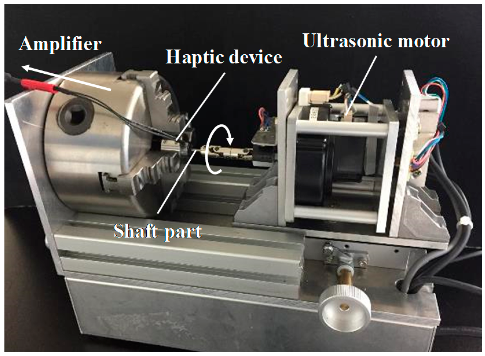
In the torque evaluation tests, the shaft part was rotated by an ultrasonic motor (USR60-E3T, Shinseikogyo Co. Ltd., Tokyo, Japan) at the rotational speed of 1.15 rad s−1.The torque was monitored using a sensor associated with the motor (Figure 2). The detection limit of the torque measurement system was 1.0 × 10⁻⁴ N m. The torque measurements were acquired at 10 ms intervals for 30 s. All evaluation tests were performed three times to monitor their reproducibility. First, the torque was evaluated when the coil voltage was 0–500 mV. Second, the voltage was repeatedly increased or decreased in a step of 500 mV in 0.001–1 s to evaluate the torque response. In this test, the frequency, amplitude, and offset voltage were set to 0.500 Hz, 0.500 Vp-p, and 0.250 V, respectively. Third, the torque was evaluated when the voltage was controlled by four types of temporal patterns that were designed based on the mechanical data from other studies [19]. We designed simplified models of typical force patterns obtained during the grasping processes of urethane resin, stainless plate, adhesive tape, and during the cutting process of paper. In the third test, the frequency, amplitude, and offset voltage were set to 0.500 Hz, 0.500 Vp-p, and 0.250 V, respectively.
2.3. Mechanical Evaluation Tests in Operating a Scissors-Type Device
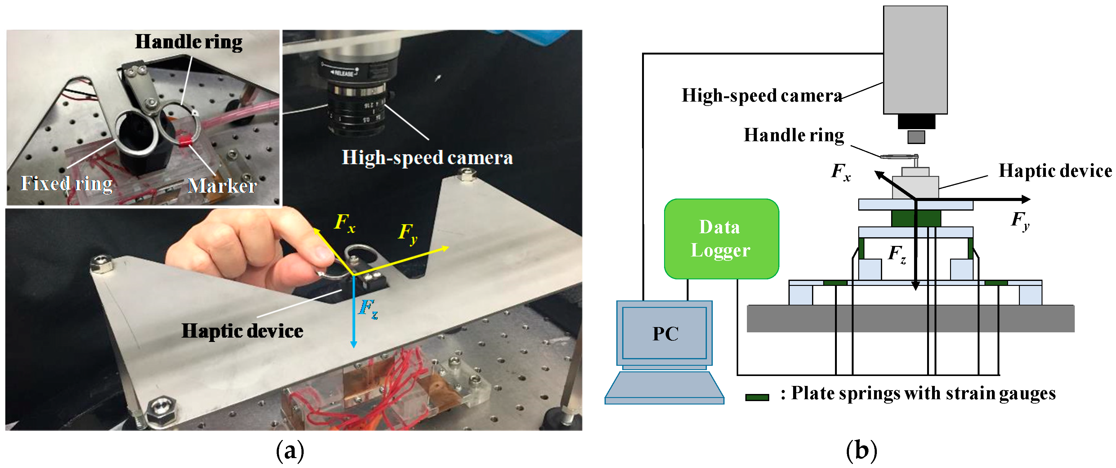
To perform the mechanical evaluation, a subject operated a scissors-type haptic device that was fixed to a mechanical evaluation system. The magnetic field around the MR fluid was controlled based on four electric profiles. A subject gripped a handle ring and opened and closed it repeatedly for 20 s. The time of opening and closing was determined by the profiled voltage on an oscilloscope. We evaluated the movement and the mechanical force of the ring using a mechanical evaluation system (shown in Figure 3) [25,26,27]. Mechanical forces were monitored using strain gauges on two leaf springs connected to a personal computer (PC) (VW9000, Keyence Co., Tokyo, Japan) via a data logger unit that comprised two electronic measurement systems (NR-500 and NR-ST04, Keyence Co., Tokyo, Japan). The detection limits of the tangential forces (Fx and Fy) and the vertical force (Fz) were 2.9 × 10⁻³, 2.0 × 10⁻⁴, and 3.9 × 10⁻² N, respectively. The ranges of the linear responses for Fx, Fy, and Fz were 8.8 × 10⁻³ to 9.8 N, 2.9 × 10⁻⁴ to 9.8 N, and 5.9 × 10⁻² to 11.8 N, respectively. During the evaluation process, we obtained high-speed images from just above the device using a high-speed camera (VW-300M, Keyence Co., Tokyo, Japan). Data from the mechanical evaluation system and the high-speed observation system were acquired at 2 ms intervals. The captured images were analyzed using Motion Analyzer software (VW-H2MA, Keyence Co., Tokyo Japan) to obtain the angle between the rings (θ).
3. Results and Discussions
3.1. Relation between the Applied Voltage and Torque
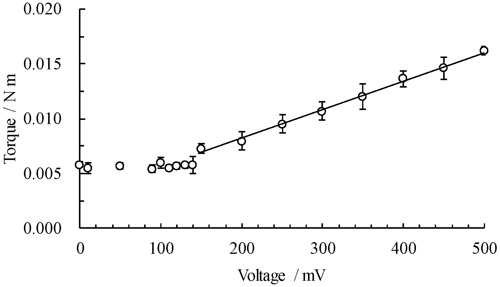
Figure 4 shows the relation between the applied voltage and measured torque. Torque remains almost unchanged when the applied voltage is within 0–140 mV: the torque is 0.006 ± 0.000 N m (torque ± standard deviation). The torque increases linearly from 0.007 ± 0.000 to 0.016 ± 0.000 N m when the applied voltage is within 150–500 mV. Equation (1) illustrates the relation between the voltage V [mV] and torque T [N m] (R2 is the determination coefficient).
T = 3.0 × 10⁻⁵V + 0.003. (R2 = 0.9955)
This result suggests that torque can be controlled in the voltage within 150–500 mV. Kwon et al. reported that the magnitude of force acting on soft tissues during a microsurgery is <1 N [28]. The developed scissors-type haptic device has a length of 25 mm starting from the fulcrum to the handle part; therefore, the difference between minimum force (0.24 N) and maximum force (0.64 N) is approximately 0.4 N. Thus, the device should realize power three times stronger than current torque for its application as a haptic device in microsurgery.
3.2. Evaluations of the Torque Response Speed
Figure 5a–c shows the temporal profiles of the torque when voltage is increased to 500 mV over specific time periods. At times 0.001, 0.5, and 1 s, the torque increased to its maximum value at 0.13 ± 0.01, 0.53 ± 0.03, and 1.03 ± 0.04 s, respectively. When the voltage decreased from 500 to 0 mV, similar response behavior was observed; the torque decreased to 0.006 N m at 0.11 ± 0.01, 0.56 ± 0.02, and 1.03 ± 0.05 s, respectively. Figure 5d shows the relation between the time taken by the voltage to increase or decrease and the response time of the torque. Torque response speed showed a maximum delay of 0.13 s when the voltage increased to or decreased from 500 mV. These results suggest that the device can obtain the resolution of 0.1 s. However, some reports showed that the typical response time of MR fluids is on the order of milliseconds. Takesue et al. reported that magnetic delay can be dependent on the internal structure of a device and the material of the bobbin [29]. Kikuchi et al. revealed that the rotational speed of the shaft also affects the response time [30].
3.3. Tactile Display of the Grasping/Cutting Processes
We previously found that the force required for grasping/cutting processes with forceps and scissors reflects the physical properties of the grasped/cut objects [19]. When grasping a urethane resin with a low elastic modulus, the grasping force increases in a one-step pattern. In contrast, when grasping a stainless-steel plate with a high elastic modulus, the force increases in a two-step pattern. When grasping an adhesive tape, a peak resulting from the peeling off of the tape from the blade was observed when opening the handle. When a subject cuts a piece of paper, the force decreases sharply at the moment at which the cutting is completed. We defined these profiles as one-step increase pattern, two-step increase pattern, double peak pattern, and drastic decrease pattern. Figure 6 shows the temporal profiles of torque and tangential force when the magnetic field around the MR fluid was controlled based on these four patterns. Figure 6A shows the torque profiles evaluated using the torque evaluation system. Figure 6B shows the tangential force profiles evaluated using the mechanical evaluation system when the handle ring was closed and opened. The wave form of the torque and tangential force corresponds approximately with each of their electric voltage profiles. Differences between the profile and the torque are highly evident when the voltage increases or decreases in a short time span. The torque and the tangential force fluctuated as follows:
- One-step increase pattern: When the electric voltage increased to 500 mV in 0.63 s, the torque reached 0.013 N m. When closing the handle, the tangential force slowly increased to 0.4 N in 0.5 s.
- Two-step increase pattern: When the electric voltage increased to 310 mV in 0.04 s and then to 500 mV in 0.23 s, the torque increased to 0.010 N m in 0.14 s and then to 0.013 N m in 0.34 s. The tangential force increased slowly similar to the one-step increase pattern, and it reached 0.6 N in 0.5 s.
- Double peak pattern: When the voltage increased and decreased to 500 mV in 0.26 s, 27 mV in 0.79 s, 462 mV in 0.99 s, and 27 mV in 1.00 s, the torque increased and decreased to 0.013 N m in 0.29 s, 0.005 N m in 0.81 s, 0.010 N m in 0.98 s, and 0.005 N m in 1.08 s, respectively. When closing the handle, the tangential force increased from 0.3 to 0.8 N in 0.8 s and decreased from 0.8 to 0.3 N in 1.3 s. When opening the handle, the force increased to 0.8 N in 1.5 s and rapidly decreased to 0.3 N in 1.52 s.
- Drastic decrease pattern: When the voltage increased and decreased to 417 mV in 0.77 s, 0 mV in 0.79 s, and 500 mV in 0.80 s, the torque also increased and decreased to 0.010 N m in 0.73 s, 0.009 N m in 0.78 s, and 0.013 N m in 0.92 s. When closing the handle, the force increased from 0.2 to 0.6 N in 1.0 s, decreased to 0.5 N in 1.05 s, and increased to 0.7 N again in 1.09 s.
These results suggest that this haptic device can display the reaction force observed during the grasping process of both soft and sticky objects. However, greater response speed and amplitude of the torque is required to display steep torque increments and sharp force fluctuations such as those observed in the two-step increase pattern and drastic increase pattern.
4. Conclusions
Herein, we evaluated the torque and operating force of the scissors-type haptic device using a torque evaluation system and a mechanical evaluation system having an attached high-speed camera. By controlling the magnetic field around the MR fluid in the device, we displayed the profiles of grasping/cutting force when using forceps and scissors. The scissors-type haptic device containing the MR fluid can display various tactile stimuli and is useful as the element technology for next-generation surgical robots. However, the torque response to the coil voltage showed a maximum delay of 0.13 s, and the maximum torque that can be presented is 0.016 N m. These abilities must be improved to accurately display the tactile information obtained during surgeries.
Author Contributions
Conceptualization, M.W., Y.A., J.N., T.K., and Y.N.; Formal analysis, M.W. and Y.A.; Funding acquisition, Y.N. and J.N.; Investigation, M.W., Y.A., and T.K.; Writing—original draft, M.W.; Writing—review & editing, Y.N.
Funding
This work was supported by Grant-in-Aids for Scientific Research (B) (No. 18H01402) from the Ministry of Education, Culture, Sports, Science and Technology, Japan (MEXT) and next-generation robot core technology development of NEDO, Japan.
Conflicts of Interest
The authors declare no conflict of interest. The funders had no role in the design of the study; in the collection, analyses, or interpretation, and writing of the manuscript, and in the decision to publish the results.
References
- Berlinger, N.T. Robotic surgery—Squeezing into tight places. N. Engl. J. Med. 2006, 354, 2099–2101. [Google Scholar] [CrossRef] [PubMed]
- Sung, G.T.; Gill, I.S. Robotic laparoscopic surgery: A comparison of the da Vinci and Zeus systems. Urology 2001, 58, 893–898. [Google Scholar] [CrossRef]
- Song, J.; Kang, W.H.; Oh, S.J.; Hyung, W.J.; Choi, S.H.; Noh, S.H. Role of robotic gastrectomy using da Vinci system compared with laparoscopic gastrectomy: Initial experience of 20 consecutive cases. Surg. Endosc. 2009, 23, 1204–1211. [Google Scholar] [CrossRef] [PubMed]
- Tsuda, S.; Oleynikov, D.; Gould, J.; Azagury, D.; Sandler, B.; Hutter, M.; Ross, S.; Haas, E.; Brody, F.; Satava, R. SAGES TAVAC safety and effectiveness analysis: Da Vinci® Surgical System (Intuitive Surgical, Sunnyvale, CA). Surg. Endosc. 2015, 29, 2873–2884. [Google Scholar] [CrossRef] [PubMed]
- Sergeeva, A.; Marleen, H.; Samer, F. Transforming work practices of operating room teams: The case of the Da Vinci robot. In Proceedings of the 36th International Conference on Information Systems, Fort Worth, TX, USA, 20–22 September 2015; pp. 1–10. [Google Scholar]
- Klatzky, R.L.; Lederman, S.J.; Metzger, V.A. Identifying objects by touch: An “expert system”. Percept. Psychophys. 1985, 37, 299–302. [Google Scholar] [CrossRef] [PubMed] [Green Version]
- Voisin, J.; Lamarre, Y.; Chapman, C.E. Haptic discrimination of object shape in humans: Contribution of cutaneous and proprioceptive inputs. Exp. Brain Res. 2002, 145, 251–260. [Google Scholar] [CrossRef] [PubMed]
- Jones, L.A.; Piateski, E. Contribution of tactile feedback from the hand to the perception of force. Exp. Brain Res. 2006, 168, 298–302. [Google Scholar] [CrossRef] [PubMed]
- Girod, S.; Schvartzman, S.C.; Gaudilliere, D.; Salisbury, K.; Silva, R. Haptic feedback improves surgeons’ user experience and fracture reduction in facial trauma simulation. J. Rehabil. Res. Dev. 2016, 53, 561–570. [Google Scholar] [CrossRef] [PubMed]
- Scilingo, E.P.; Bicchi, A.; Rossi, D.D.; Scotto, A. A magnetorheological fluid as a haptic display to replicate perceived biological tissues compliance. In Proceedings of the 1st Annual International IEEE EBMS Special Topic Conference on Microtechnologies in Medicine and Biology, Lyon, France, 12–14 October 2000; pp. 229–233. [Google Scholar]
- Ahmadkhanlou, F.; Washington, F.N.; Bechtel, S.E. Modeling and control of single and two degree of freedom magnetorheological fluid-based haptic systems for telerobotic surgery. J. Intell. Mater. Syst. Struct. 2009, 20, 1171–1186. [Google Scholar] [CrossRef]
- Oh, J.S.; Kim, J.K.; Lee, S.R.; Choi, S.B.; Song, B.K. Design of tactile device for medical application using magnetorheological fluid. J. Phys. Conf. Ser. 2013, 412, 012047. [Google Scholar] [CrossRef] [Green Version]
- Kameyama, T.; Tsujita, T.; Konno, A.; Jiang, X.; Abiko, S.; Uchiyama, M. Displaying Cutting Force of Soft Tissue Using MR Fluid for Surgical Simulators. In Proceedings of the 2014 IEEE Haptics Symposium (HAPTICS), Houston, TX, USA, 23–26 February 2014; pp. 283–288. [Google Scholar]
- Yu, S.; Guo, S.; Zhang, L.; Yin, X. MR Fluid Interface of Endovascular Catheterization Based on Haptic Sensation. In Proceedings of the 2016 IEEE International Conference on Mechatronics and Automation, Harbin, China, 7–10 August 2016; Volume 1, pp. 454–458. [Google Scholar]
- Kim, S.; Kim, P.; Park, C.Y.; Choi, S.B. A new tactile device using magneto-rheological sponge cells for medical applications: Experimental investigation. Sens. Actuators A Phys. 2016, 239, 61–69. [Google Scholar] [CrossRef]
- Song, B.K.; Oh, J.S.; Kim, P.; Kim, S.; Choi, S.B. Repulsive torque control of a robot-assisted surgery system using a magnetorheological haptic master. J. Syst. Control Eng. 2016, 230, 1116–1125. [Google Scholar] [CrossRef]
- Kim, P.; Kim, S.; Park, Y.D.; Choi, S.B. Force modeling for incisions into various tissues with MRF haptic master. Smart Mater. Struct. 2016, 25, 035008. [Google Scholar] [CrossRef]
- Carlson, J.D.; Jolly, M.R. MR fluid, foam and elastomer devices. Mechatronics 2000, 10, 555–569. [Google Scholar] [CrossRef]
- Waga, M.; Aita, Y.; Noma, J.; Nonomura, Y. Tactile Feels in Grasping/Cutting Processes with Scissors. Technologies 2018, 6, 66. [Google Scholar] [CrossRef]
- Guerrero-Sanchez, C.; Lara-Ceniceros, T.; Jimenez-Regalado, E.; Raşa, M.; Schubert, U.S. Magnetorheological fluids based on ionic liquids. Adv. Mater. 2007, 19, 1740–1747. [Google Scholar] [CrossRef]
- López-López, M.T.; Gómez-Ramírez, A.; Durán, J.D.; González-Caballero, F. Preparation and characterization of iron-based magnetorheological fluids stabilized by addition of organoclay particles. Langmuir 2008, 24, 7076–7084. [Google Scholar] [CrossRef] [PubMed]
- Noma, J.; Abe, H.; Kikuchi, T.; Furusho, J.; Naito, M. Magnetorheology of colloidal dispersion containing Fe nanoparticles synthesized by arc-plasma method. J. Magn. Magn. Mater. 2010, 322, 1868–1871. [Google Scholar] [CrossRef]
- Ashtiani, M.; Hashemabadi, S.H.; Ghaffari, A. A review on the magnetorheological fluid preparation and stabilization. J. Magn. Magn. Mater. 2015, 374, 716–730. [Google Scholar] [CrossRef]
- Rabbani, Y.; Ashtiani, M.; Hashemabadi, S.H. An experimental study on the effects of temperature and magnetic field strength on the magnetorheological fluid stability and MR effect. Soft Matter 2015, 11, 4453–4460. [Google Scholar] [CrossRef] [PubMed]
- Nonomura, Y.; Fujii, T.; Arashi, Y.; Miura, T.; Maeno, T.; Tashiro, K.; Kamikawa, Y.; Monchi, R. Tactile impression and friction of water on human skin. Colloids Surf. B 2009, 69, 264–267. [Google Scholar] [CrossRef] [PubMed]
- Nonomura, Y.; Miura, T.; Miyashita, T.; Asao, Y.; Shirado, H.; Makino, Y.; Maeno, T. How to identify water from thickener aqueous solutions by touch. J. R. Soc. Interface 2012, 9, 1216–1223. [Google Scholar] [CrossRef] [PubMed]
- Nonomura, Y.; Saito, R.; Takahashi, A. Friction at fingertip surface during water contact process. Bull. Chem. Soc. Jpn. 2015, 88, 949–954. [Google Scholar] [CrossRef]
- Kwon, D.S.; Woo, K.Y.; Song, S.K.; Kim, W.S.; Cho, H.S. Microsurgical Telerobot System. In Proceedings of the 1998 IEEE/RSJ International Conference on Intelligent Robots and Systems, Victoria, BC, Canada, 17 October 1998; pp. 945–950. [Google Scholar]
- Takesue, N.; Furusho, J.; Kiyota, Y. Fast response MR-fluid actuator. J. Soc. Mech. Eng. Int. J. Ser. C 2004, 47, 783–787. [Google Scholar] [CrossRef]
- Kikuchi, T.; Noma, J.; Akaiwa, S.; Ueshima, Y. Response time of magnetorheological fluid–based haptic device. J. Intell. Mater. Syst. Struct. 2016, 27, 859–865. [Google Scholar] [CrossRef]
Figure 1.
Haptic device and haptic display system: (a) photograph of the haptic device and (b) schema of the device.
Figure 1.
Haptic device and haptic display system: (a) photograph of the haptic device and (b) schema of the device.

Figure 2.
Snapshot of the torque evaluation system.

Figure 3.
Photograph (a) and schema (b) of a scissors-type haptic device and mechanical evaluation system.
Figure 3.
Photograph (a) and schema (b) of a scissors-type haptic device and mechanical evaluation system.

Figure 4.
Relation between electric voltage and torque.

Figure 5.
Response ability of the device. (a–c) Changes in the torque (solid lines) and in the voltage (dotted lines). (d) Relation between the increasing/decreasing time of the voltage and the response time of the torque.
Figure 5.
Response ability of the device. (a–c) Changes in the torque (solid lines) and in the voltage (dotted lines). (d) Relation between the increasing/decreasing time of the voltage and the response time of the torque.

Figure 6.
Tactile display during the grasping/cutting process. (A) Change in the torque (solid lines) and the applied voltage (dotted lines) over time. (B) Change in the tangential force (solid lines) and θ (dotted lines) when a subject operates the scissors-type haptic device. Dark gray zones indicate the closing phase and light gray zones indicate the opening phase of the handle ring. Each voltage pattern is as follows: (a) one-step increase pattern, (b) two-step increase pattern, (c) double peak pattern, and (d) drastic decreasing pattern.

© 2019 by the authors. Licensee MDPI, Basel, Switzerland. This article is an open access article distributed under the terms and conditions of the Creative Commons Attribution (CC BY) license (http://creativecommons.org/licenses/by/4.0/).
Share and Cite
MDPI and ACS Style
Waga, M.; Aita, Y.; Noma, J.; Kikuchi, T.; Nonomura, Y. Scissors-Type Haptic Device Using Magnetorheological Fluid Containing Iron Nanoparticles. Technologies 2019, 7, 26. https://0-doi-org.brum.beds.ac.uk/10.3390/technologies7010026
AMA Style
Waga M, Aita Y, Noma J, Kikuchi T, Nonomura Y. Scissors-Type Haptic Device Using Magnetorheological Fluid Containing Iron Nanoparticles. Technologies. 2019; 7(1):26. https://0-doi-org.brum.beds.ac.uk/10.3390/technologies7010026
Chicago/Turabian StyleWaga, Mioto, Yuuki Aita, Junichi Noma, Takehito Kikuchi, and Yoshimune Nonomura. 2019. "Scissors-Type Haptic Device Using Magnetorheological Fluid Containing Iron Nanoparticles" Technologies 7, no. 1: 26. https://0-doi-org.brum.beds.ac.uk/10.3390/technologies7010026
Note that from the first issue of 2016, this journal uses article numbers instead of page numbers. See further details here.