
Open Source 3D-Printable Planetary Roller Screw for Food Processing Applications


1
Department of Mechanical Engineering-Engineering Mechanics, Michigan Technological University, Houghton, MI 49931, USA
2
Department of Electrical & Computer Engineering, Michigan Technological University, Houghton, MI 49931, USA
3
Department of Material Science & Engineering, Michigan Technological University, Houghton, MI 49931, USA
4
Department of Electronics and Nanoengineering, School of Electrical Engineering, Aalto University, FI-00076 Espoo, Finland
*
Author to whom correspondence should be addressed.
Technologies 2021, 9(2), 24; https://0-doi-org.brum.beds.ac.uk/10.3390/technologies9020024
Submission received: 10 February 2021
/
Revised: 14 March 2021
/
Accepted: 1 April 2021
/
Published: 7 April 2021
(This article belongs to the Special Issue Open Source Agriculture Technology)
Abstract
:Historically, open source agriculture (OSA) was based on grassroots technology generally manufactured by hand tools or with manual machining. The rise of distributed digital manufacturing provides an opportunity for much more rapid lateral scaling of open source appropriate technologies for agriculture. However, the most mature distributed manufacturing area is plastic, which has limited use for many OSA applications. To overcome this limitation with design, this study reports on of a completely 3D-printable planetary roller screw linear actuator. The device is designed as a parametric script-based computer aided design (CAD) package to allow for the easy adaption for a number of applications such as food processing at different scales. The planetary roller screw is fabricated in dishwasher-safe polyethylene terephthalate glycol (PETG) on an open source machine and tested using an open source testing platform to determine if it could maintain a constant load without slipping and the maximum force. Then, this output is compared to a direct screw press using the same materials. The results found that the maximum force is more than doubled for the roller screw actuator using the same materials, making them adequate for some food processing techniques. Future work is outlined to improve the performance and ease of assembly.
1. Introduction
Although much open source agriculture (OSA) was grassroots technology [1] born of necessity [2], it is emerging as a commons-based [3] peer production [4], and some have even argued that open source agriculture is becoming a social movement [1,5]. For example, the MIT Media Lab Open Agriculture Initiative (OpenAg) believes that the precursor to a sustainable food system will be the creation of an open-source ecosystem of technologies that enable and promote transparency, networked experimentation, education, and hyper-local production [6]. This distributed farming system is based on communication, sensing, data collection, and sharing as well as automation to enable a network effect or the Internet of Food and the next agricultural revolution [7]. As the organizers of the Gathering for Open Agricultural Technology (GOAT) argue, “The technologies that produce our food and the data about our food system should be public, and enable control by the farms and farmers that produce it” [8]. OSA follows the same open source approach long established to be beneficial in sustainable development [9,10]. Specifically, open source appropriate technology (OSAT) [11] consists of technologies that provide for sustainable development while being designed in the same fashion as free and open source software [12,13,14,15]. The open source model functions on a gift culture [16], where everyone benefits from generous sharing. OSAT specifically consists of technologies that are easily and economically utilized from readily available resources by local communities to meet their needs [11,17,18]. OSAT is determined by environmental, cultural, economic, and educational resource constraints of specific local communities long established for what makes an “appropriate technology” (AT) [19,20,21]. The networked world now enables innovation and collaboration in the appropriate technology space [22,23] allowing for full OSAT [11,24,25]. OSAT for agriculture covers a wide range of agricultural tools [2] from often low-tech designs from grassroots innovations in India from the Honey Bee Network [26,27,28,29] to precision agriculture and food computing of OpenAg [6,30,31]. One of the most ambitious OSAT projects is Open Source Ecology, which aims to create open source versions of all the tools needed for civilization starting with the tractor for farming [32,33,34,35].
One open source technology that is particularly well-suited for fabricating OSAT for OSA is the 3D printer [36,37]. The open source self-replicating rapid prototyper (or RepRap) [38,39,40,41] has radically reduced the cost of additive manufacturing [42]. Already, several solar-powered versions of the RepRap have been developed, which enable green distributed manufacturing anywhere the sun shines [43,44,45,46,47]. The sharing community that has resulted from RepRap and the resultant desktop 3D printer industry has created an exponentially growing number of free designs [48] now numbering in the millions. These designs can be digitally replicated anywhere in the world with access to the tools that now cost <$250. It is now well-established that these low-cost open source 3D printers can reduce costs for mass manufactured consumer goods on average by 90–99% [48,49,50]. In general, the greater the percentage of a product that is 3D printed, the greater the potential economic savings. Three-dimensional (3D) printers can also be applied to solving problems in the developing world for farmers that use labor-intensive agricultural hand tools, as a growing number of 3D-printed tools can be used for improving the efficiency of agriculture [45,51]. The cost-saving nature of distributed manufacturing of 3D printing has also been shown to benefit developed-world small-scale organic farmers through a wide array of devices including fruit pickers, chicken feeders, hose splitters, and hydroponics [52]. These agricultural tools can be sophisticated such as tools for measuring nitrates in soil, water, and forage [53] or for water quality testing that replaces thousands of dollars of commercial handheld instrumentation [54]. However, often, these tools are mechanical in nature and not overly sophisticated such as screw presses. The tensile strength of common 3D-printed materials [55,56,57,58,59] limits the forces for simple screw presses, so often, metal screws or bolts are used on devices such as the open source cassava press [52]. This increases the costs and forces external dependency for the “vitamins” (non-3D-printed parts).
The most popular commercial design for fruit presses cannot be adequately reproduced cheaply using all-plastic common desktop 3D printing. This is not due to the design itself, but rather the material properties of 3D-printed plastics. Although there are open source systems that can 3D print higher strength plastics such as polycarbonate [60], the lower-cost 3D printers are still largely limited to printing common thermoplastics such as polylactic acid (PLA) and a glycol-modified version of polyethylene terephthalate (PETG). This limits the effective loading of the pressing mechanism. To allow the construction of an agricultural product press (e.g., a fruit press) with only 3D printing technologies using common plastics, the design of the structure of the pressing mechanism needs to be made stronger than a traditional lead screw while maintaining a small package to limit cost.
This study reports on the open-source design of a completely 3D printable planetary roller screw linear actuator. The device is designed as a parametric script-based computer aided design (CAD) package to allow for easy adaption for a number of applications such as food processing at different scales. The planetary roller screw is fabricated in PETG polymer filament on an open source fused filament-based 3D printing machine and tested using an open source testing platform to determine that it could maintain a constant load without slipping and the maximum force. Then, this output is compared to a direct screw press using the same material. The results are presented and discussed for food processing applications.
2. Materials and Methods
2.1. Roller Screw Design
Here, the primary solution explored was the use of a planetary roller screw linear actuator. These actuators were originally designed by C.B. Strandgren in 1954 [61]. They are low-friction, high duty-cycle linear actuators that can deliver large amounts of power and torque with lower friction and in a relatively small package [61]. The construction of these actuators involves the use of an outer nut or shell with threading, coupled to a number of threaded rollers that transfer the rotational power from the nut to the linear motion of a central lead screw. Another way to approach their function would be to envision a planetary gear system that is extruded into screws rather than 2D gears. This design was adapted and used for this project.
There are three primary functional parameters to a planetary roller screw that define the major functional relationships between each element. These elements are listed in Table 1 with appropriate units for each.
These three functional parameters in Table 1 define the functions of the entire planetary roller screw system and are used to define a number of other functional variables down the line. Most importantly, they define the gear ratios between the threaded units, which can be used to determine the performance of these actuators in a specific application. Equation (1) shows the resulting gear ratio between the outer nut and the central screw.
Note that the only major parameter that affects this ratio is the number of thread starts. It is also important to note that mathematically, these planetary screw systems cannot operate with less than 3 screw starts on the central screw. It will be shown later that although a minimum of 3 thread starts is possible, it is rather impractical for real-world use.
These functional parameters also define the major diameters of the other components in the system. Table 2 shows the relationship between the primary functional parameters and the major diameters of the other components:
These parameters define the basic dimensions and mechanical requirements of the planetary roller screw. However, there are other values that need to be defined to completely constrain the design of the planetary roller screw shown in Table 3.
2.2. Bill of Materials (BOM) for 3D-Printed Parts
The BOM of the 3D-printed parts in shown in Table 4 for the roller screw assembly, and those for the test stand assembly are shown in Table 5. An alternate top retainer is also included in Table 4 for validation testing of a similar direct press screw mechanism. Full details of the design are shown in Appendix A.
2.3. Roller Screw Assembly
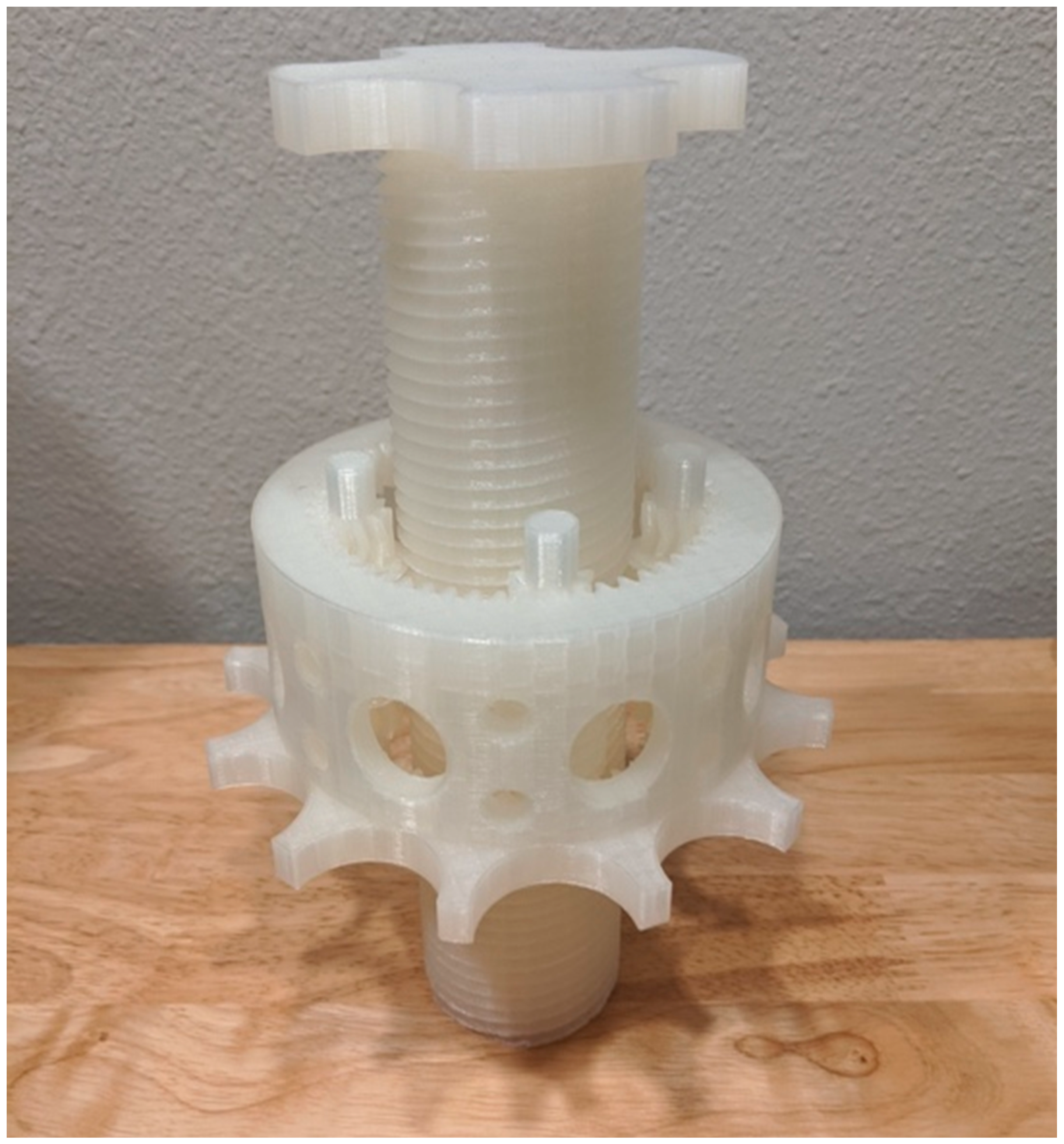
A fully 3D-printed and assembled roller screw assembly is shown in Figure 1. This example was 3D printed on an open source Prusa Mk3S in natural PLA at 0.2 mm layer height, but it is amenable to replication on any RepRap-class fused filament 3D printer. Complete source for the assembly can be found on Github at [62].
2.4. Roller Screw Testing and Validation
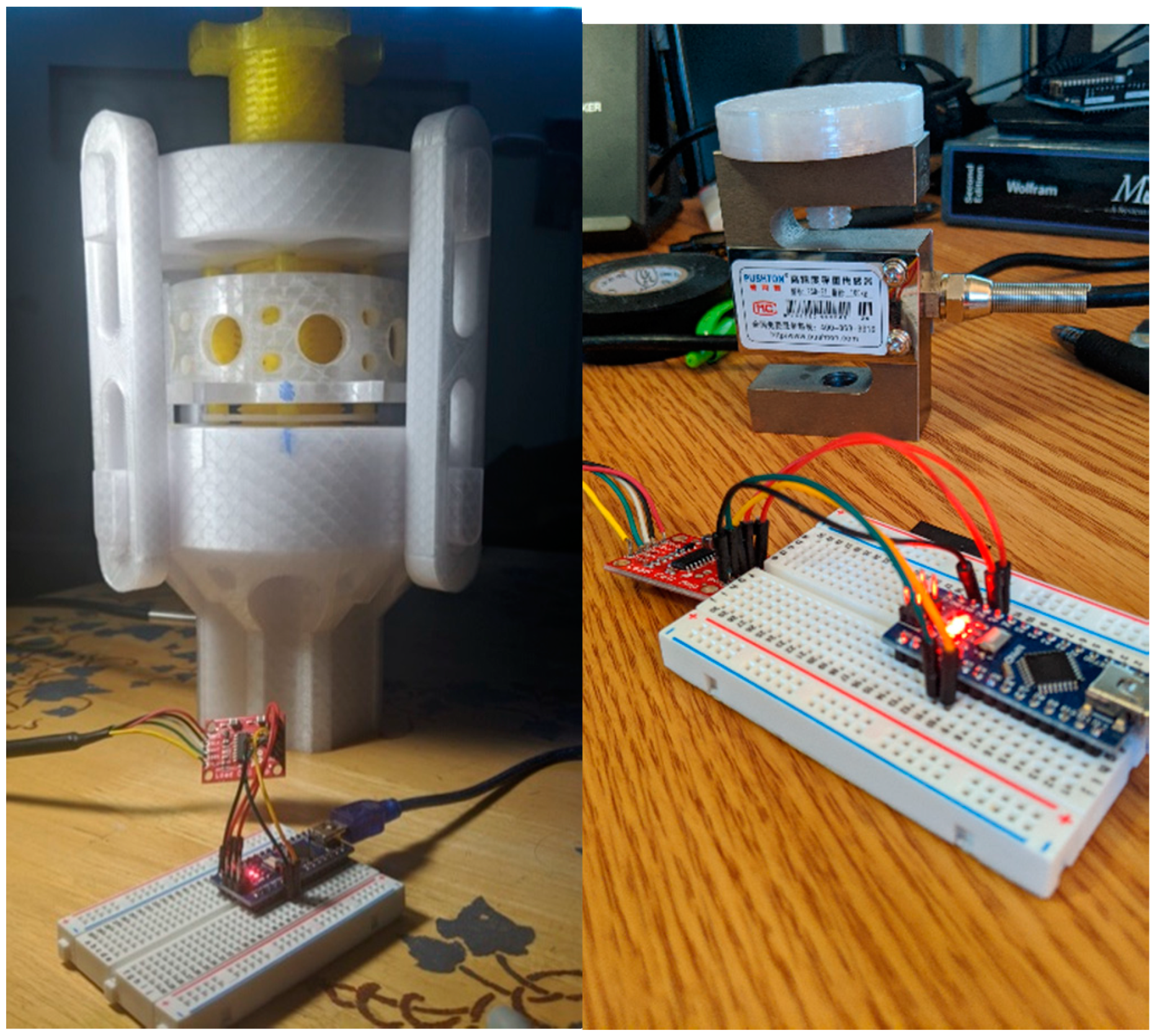
Testing was performed with the roller screw and modular testing assembly made up the test materials shown in Table 6. Although initial prototyping was done in PLA, which is the most common 3D-printed plastic, it is not dishwasher safe. PETG has a heat distortion temperature of 70 °C and vicant softening temperature of 85 °C. Most home dishwashers operate at about 49 °C, which enables PETG components (unlike PLA) to be cleaned in most home dishwashers even without annealing the 3D-printed part. Both the roller screw assembly and test rig assembly were printed with PETG using an open source Lulzbot TAZ6 3-D printer [63]. Default high-detail print settings were used in a TAZ6 3D printer with a layer height of 0.14 mm. All tests were run on PETG 3D-printed roller screws and testing rigs. An S-type load sensor was used to measure the force the screw was able to impart during actuation.
The load sensor was assembled and calibrated prior to insertion into the test rig assembly. The load cell wires are soldered to the input side of the SparkFun HX711. The wire coloring on load cells is standardized. Connect pins on the other side of the amplifier to an Arduino. The entire wiring diagram be seen in Figure 2.
After connecting all components, then, Arduino was used to calibrate the load cell. The HX711 library was downloaded from the Arduino IDE library manager. The public domain “SparkFun_HX711_Calibration.ino” calibration code was available from the SparkFun website and can alsobe downloaded from the project github repository [62]. A 9.07 kg weight was placed on top of the load cell, and the calibration factor in the calibration code was adjusted until the output on the serial monitor matched the weight. Once the calibration was completed, the calibration factor was placed into the “run_scale.ino” code found in the same locations as the calibration code. The weight was added to the top of the load cell again to confirm that the operational code was correct.
After the setup process, the S-type load cell was fitted into the hole in the bottom retainer of the test rig. Three-dimensional (3D)-printed plates were fastened into the M12 holes on the top and bottom of the load sensor to hold it in place and provide an even surface for roller screw contact. The tests were performed by twisting the collar, while the center screw was held in place by hand to prevent rotation. This is shown in Figure 3.
Using the completed assembly described above, the roller screw was first tested to determine if it could maintain a constant load without slipping and what the maximum force could be obtained from the current build of this mechanism. Second, a test was done to determine the increase in loading per rotation of the collar. At each step, the collar was rotated 90 degrees and held static for a short amount of time. At each loading step, the force on the roller screw mechanism lowered after the hand was removed from the collar. Tests were repeated six times.
2.5. Validation Testing Versus Control Direct Press Screw
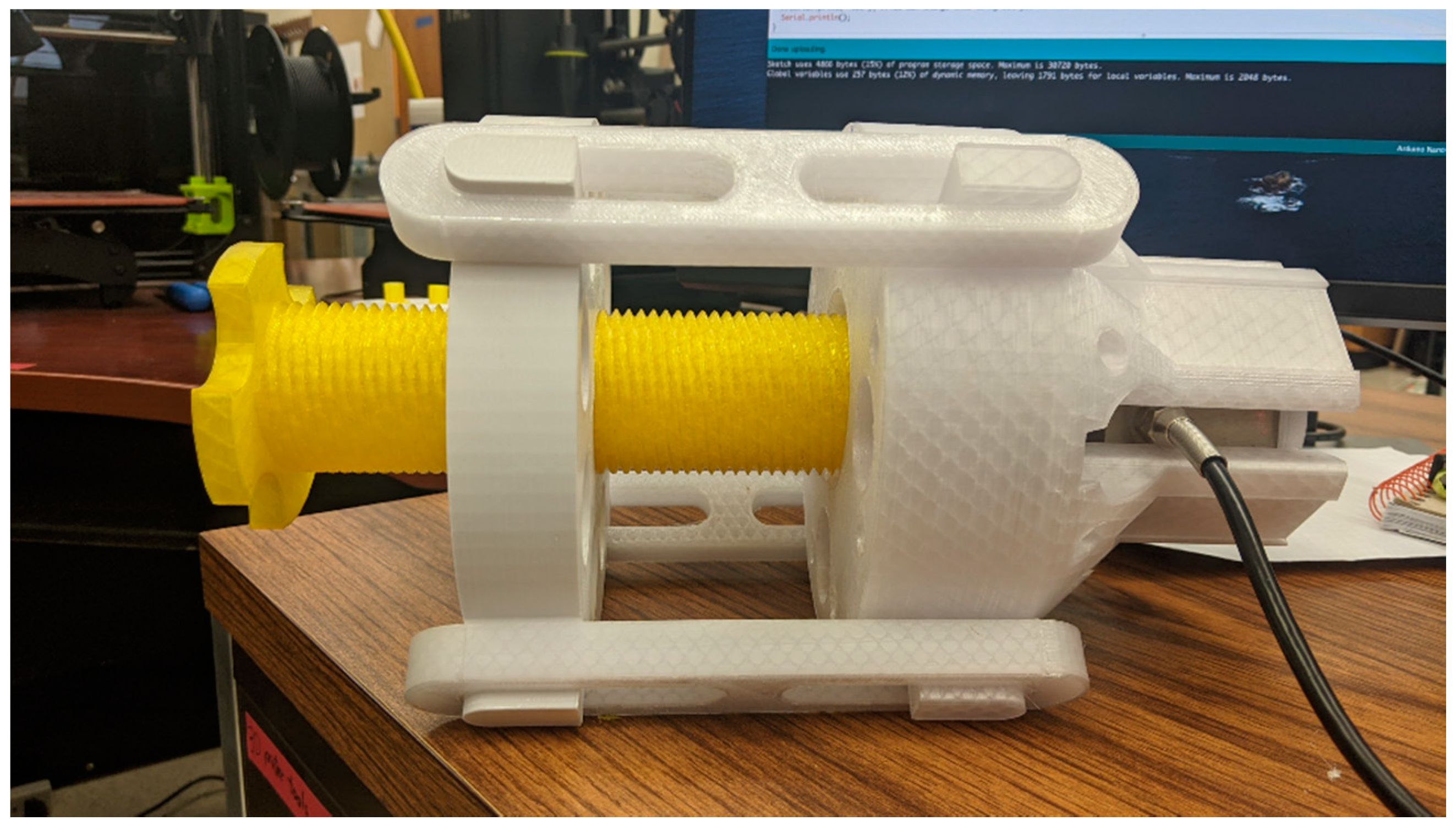
Then, a direct press screw was created using the same central lead screw and test stand assembly to determine how much force was generated compared to a roller screw press. In this alternate assembly, the top retainer was replaced with a threaded version (where the original was a through-hole with clearance for the screw), and the roller screw assembly was removed. All other materials remained unchanged. This configuration can be seen in Figure 4.
Testing with this version of the screw used the same method to startup and acquire data as with the roller screw test. However, for this series of testing, the lead screw is twisted from the top until no more force can be applied. The same operator was used in the manual twisting of this mechanism as in previous tests. The performance of the direct press screw was measured during 10 consecutive tests in terms of applied force over a duration. The direct press screw was rotated to apply force onto the load cell until it was no longer capable of completing this operation. After a varying duration of time, the force was then removed from the load cell by rotation of the screw in the opposite direction until it was no longer touching the load cell top screw plate.
3. Results
3.1. Maintain a Constant Load without Slipping Test
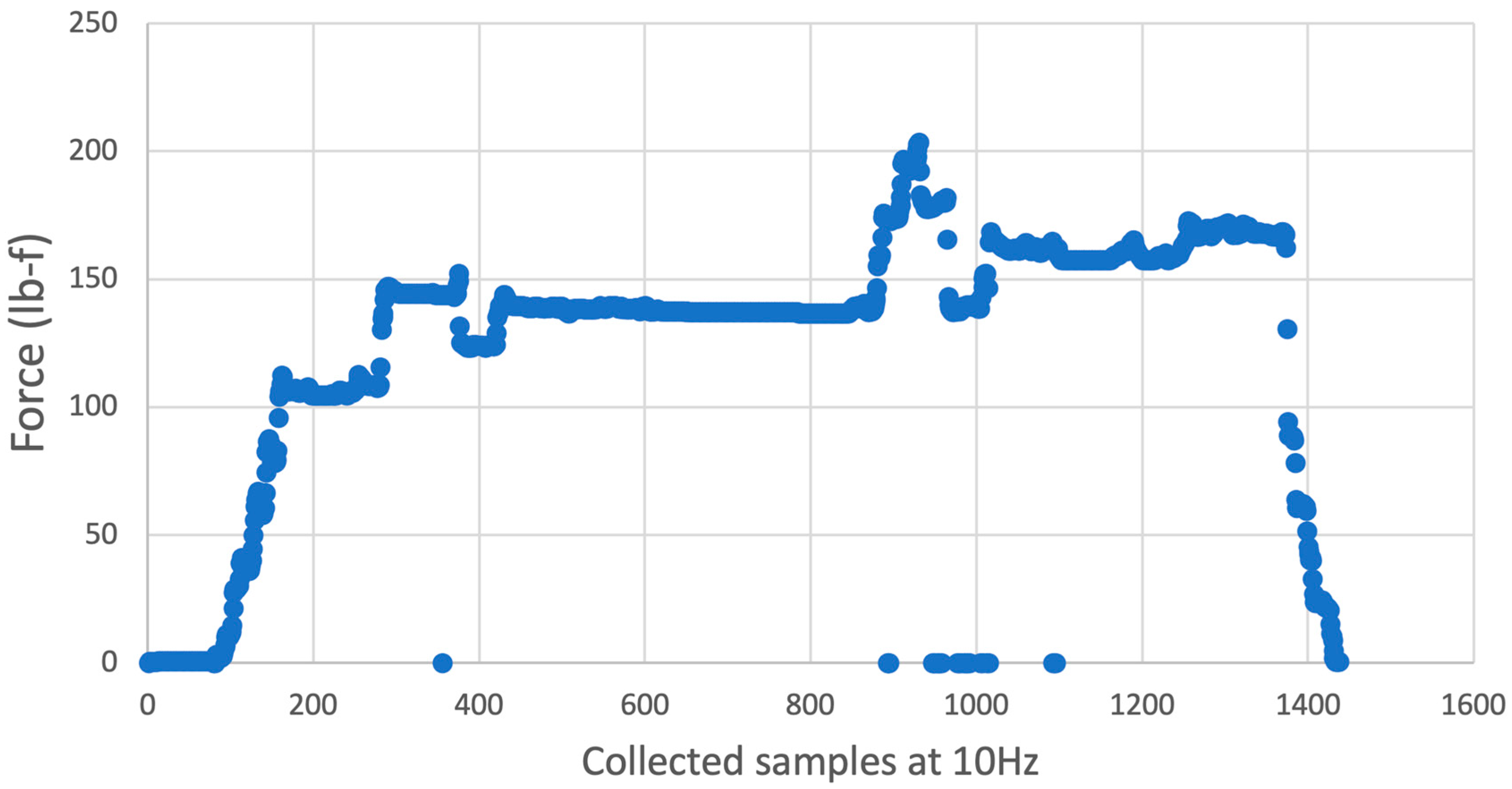
The first test determined that the current roller screw assembly could maintain a 160 lbf compressive load against the S-type load sensor. However, when the loading exceeded 200 lbf, the roller screw teeth started de-meshing with the central screw. This de-meshing can be seen most prominently around the 1000th collected sample in Figure 5. Then, the planetary roller screw was turned in the opposite direction to remove the load on the load sensor. No visual damage was observed on the rollers or central screw during the first test.
3.2. Increase in Loading Per Rotation of the Collar
The results of a representative loading test are shown in Figure 6. The planetary roller screw was able to maintain an average of up to 85.73 kg. At the 250th sample, the collar was rotated again, but the rollers failed and slipped off of the central screw. During the seventh repeat of this test, one of the rollers experienced a failure where the central screw sheared off its threads. The test ended after this event.
3.3. Direct Screw Press Performance
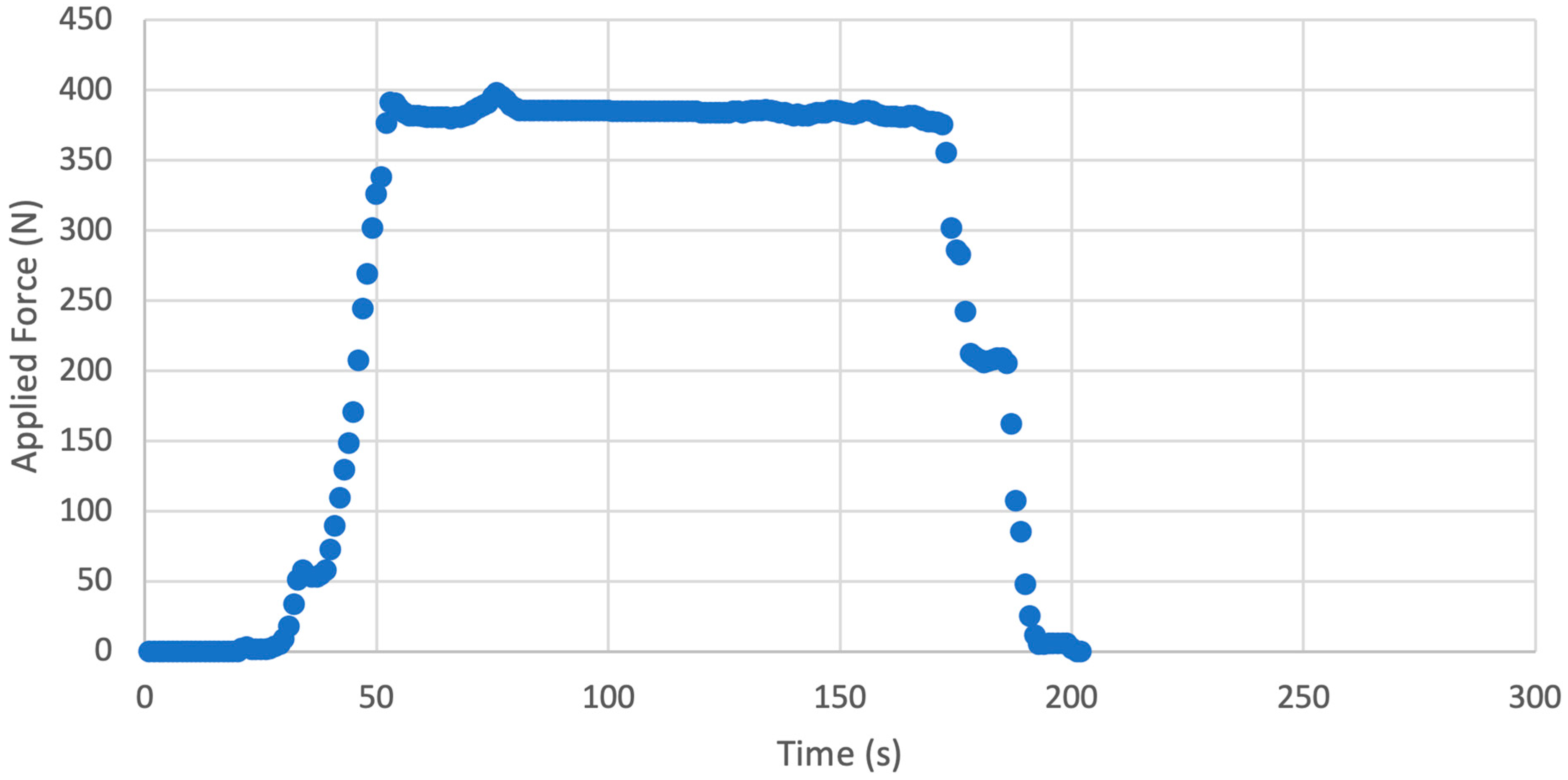
The results of the direct screw press are shown in Figure 7 for the most representative experiment. The average maximum force was 403.5 N.
4. Discussion
This is the first application of a roller screw design made for both AM, parametric, and for distributed manufacturing. The results that double the applied force was able to be tolerated with the same material represents a major step forward in the amplification of mechanical strength for fused filament fabrication (FFF)-based AM. The overall effectiveness of the 3D-printed planetary roller screw is discussed in the context of the experimental results. Afterwards, a path forward is described for future research.
4.1. Force Exertion and Pressure as a Function of Angle
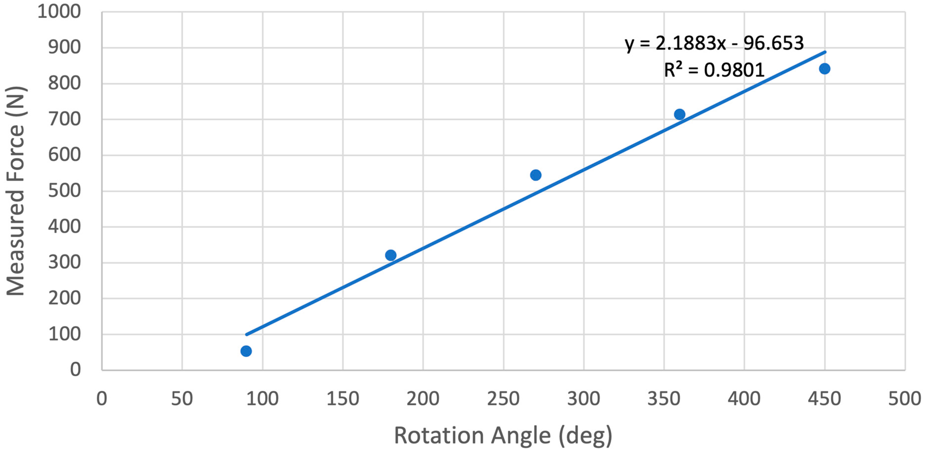
The measured force after each 90-degree rotation was averaged together and plotted in Figure 8. For every degree of rotation of the main collar, the central screw exerted on average of 2.19 N onto the load cell. The same force data are divided by the area of the 50 mm diameter pressure plate base to determine the exerted pressure and can be seen in Table 7. This version of the roller screw is able to exert approximately 428 kPa onto a flat surface. The pressure exerted by this mechanism is dependent on the area of the crushing surface; a press plate with ¼ the area would be able to deliver four times the pressure before entering the roller slippage failure mode of the current design.
4.2. Comparison to Conventional Screw Press
The screw press assembly was only able to generate roughly half the approximate force that the roller screw testing yielded. The average maximum force delivered from 10 trials was found to be approximately 403 N. The pressure delivered by this screw was calculated to be 206 kPa or roughly 2 atmospheres of pressure at sea level. This direct press method encountered a large amount of friction during actuation from the rotating central screw against the fixed load sensor. This friction is believed to have reduced the overall effectiveness of the system by increasing the difficulty in rotating the lead screw. This limitation is not present in the roller screw mechanism because there are no large flat surface contact areas that can cause static friction.
4.3. Future Work
Throughout the process of designing this initial prototype, a number of additional ideas and potential improvements have been thought of and even explored. The following section will briefly go over some of the potential future developments for this design.
4.3.1. Overcoming Mechanism Failures
The mechanism failures discussed in the second test of the roller screw are preventing the planetary roller screw from reaching maximum force application. This can be accomplished by adding additional rollers into the collar assembly to better distribute force. However, manually inserting eight rollers into the collar housing, holding them in place, aligning them, and threading the central screw through them is an incredibly time-consuming process that is prone to failure. Overall, one of the largest difficulties with the current design is the assembly of the central roller screw. The components can be difficult to manage by hand and are difficult to align properly for complete assembly. Potential design changes could allow the entire roller screw to be printed at once with all components pre-located where they are required. Future roller screw mechanisms will need to be printed in place to overcome assembly issues from adding more rollers to increase mechanism strength. This can be done with a printer with two heads: one printing in PLA and another in a water-soluble material such as polyvinyl alcohol (PVA).
If this were implemented properly, a user would simply need to print out the entire system once, remove, and begin using the system immediately. This would bring about quicker turn-around times and simpler end-user application for these systems. Modifying this design to be print-in-place will require design changes to allow everything to be printed properly without binding or meshing. The tolerances between the threads would need to be controlled so that there is adequate distance between the roller threads as well as the outer nut threads. Without appropriate tolerances, the threads could bind together, making operation impossible.
Keeping the rollers within the assembly would also be a challenge, as the current design relies on the gears as well as the central screw to keep the rollers within the assembly. The most likely approach to printing-in-place would not include the central screw, as there are typically other components to the overall system that need to be installed before the central screw. Thus, the approach to keeping the rollers within the assembly must be changed for the print-in-place design. This may be in the form of support material, a “pseudo-central screw”, or any other means to prevent the rollers from falling out of the assembly before the central screw is installed.
4.3.2. Increasing Overall Force
The primary delivery method of power to the roller screw is through the application of torque to the outer nut. This torque is proportional to the total force that the press can exert. If the given material can withstand larger forces and higher torques than the original design allows, the simplest way to increase the force exerted by the press is to increase the torque on the outer nut. This can be done by increasing the size of the moment arm on the outer nut. The current design has rather short flanges which were pressed by the users’ fingers. By making these flanges longer and adding more weight to the end of the flanges, the user can effectively increase the torque they can exert on the outer nut without an increase in force. This is a commonly used method within manual metal presses and cutters that use a large overhead wheel with a weight on one side. The user would take the weight and “throw” it to create large amounts of linear force on the work piece. The same principal can be applied here.
Further analysis of the mechanical system, such as through finite element analyses (FEA), would allow the overall system to become more rigid and tolerant of component variance. With such improvements, the overall force that can be applied to the system can be increased without changing materials nor significantly increasing the size of the system. These targets for future work would broaden the applicability of the system with the potential to optimize the design for specialized needs where required.
4.3.3. Migration to SolidPython
While designing this project, one goal was to make the design parametric so that it may fit into many different requirement sets. Although this design was originally intended for use in a fruit press, the design scope can be expanded to other areas where a high-duty cycle, low-friction, linear actuator is needed. Although OpenSCAD has facilities to create a parametric design, the design of the OpenSCAD Language can quickly become restrained and limited as the complexity of the design increases. This started to become a problem as time went on and the overall code base became difficult to control and manage while maintaining parametric design.
While searching for solutions to some of the problems encountered with OpenSCAD, SolidPython was found as a potential alternative. SolidPython is a Python3 module that encapsulates OpenSCAD within Python3 and allows the generation and exporting of OpenSCAD code. This allows developers to use many of the features and systems built into Python3 for developing OpenSCAD Code. Some of these features, such as encapsulation, polymorphism, and Front-End User Interfaces, are difficult or impossible to implement directly into OpenSCAD. However, these features are easy to implement within the context of SolidPython. Potential front-end features include the following:
- Graphical User Interface
- Interactive 3D rendering
- Easy import of external thread standards
- Easy import of external housings
- Easy import of alternate gear methods
- Quick-switching between various design features
- Force vs. torque estimations
- Embedded operational simulation
With some of these great advantages available, SolidPython was explored more, and a code base was developed that can use some of these features. That code base is located on the GitHub repository [62] and is released under the same license as the rest of the Roller Screw OpenSCAD code in a separate branch.
4.3.4. Roller Encapsulation
As can be seen in the original design, the roller screw typically used the spacers as retainers for the rollers to prevent them from falling out of the assembly. This requirement adds complexity to the design and is a source of increased friction as the spacers are pressed against the walls of the roller screw. Our design solved these issues by using herringbone gears for the timing gears. Herringbone gears are capable of taking some level of axial load and therefore can keep the rollers retained.
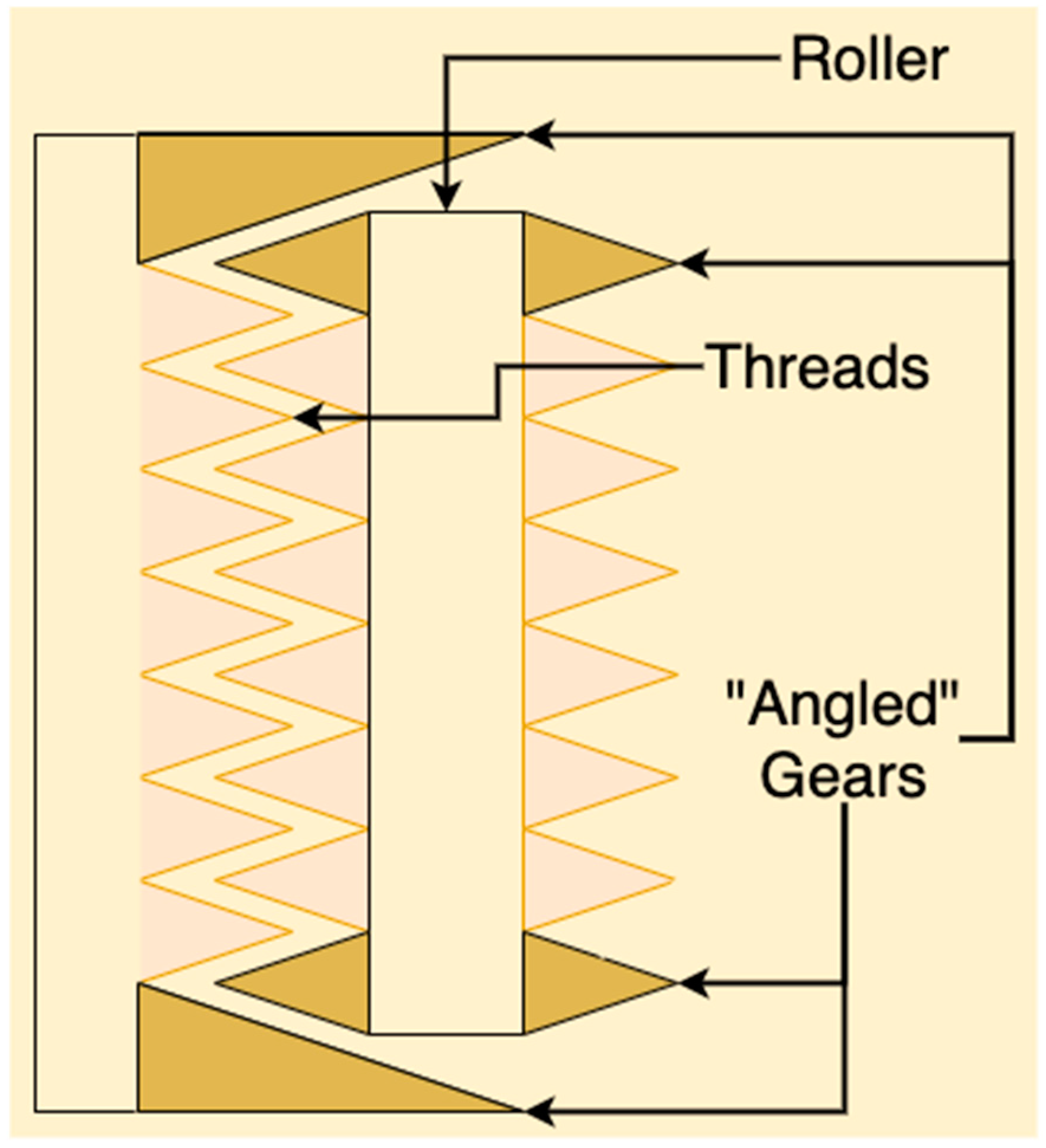
However, there are other potential solutions to this issue. One other potential solution that has not been thoroughly explored yet is the use of an “Angled” ring gear. Figure 9 shows a mockup of what this may look like. Although first impressions may lead one to believe these are bevel gears, standard bevel gears cannot operate in the manner shown, because the axe of rotation for the roller and the nut are parallel. Bevel gears can only operate when the two reference cones of the gears form a line at the mating connection of the gears.
In contrast, the “Angled” ring gear would require a new gear tooth geometry. This is because, in essence, as the tooth moves up and along the slanted gear face, the module of the gear is changing. This is because the number of teeth of the gear is constant; however, the diameter of the gear is changing along the slant. This creates a gear tooth that would appear to get larger as it moves up the gear. This slanted gear could be used for limiting the axial movement of the rollers while possibly minimizing the friction between the rollers and the outer nut.
4.3.5. Food Processing Applications
The maturity of open-source appropriate technologies being applied to agriculture are maturing in the research and development arena, focusing largely on electronics-based applications to agriculture [64,65,66,67]. There are also sophisticated systems that are open source and can be used to sterilize for example rooms in the agriculture industry as well as for research and development and medical applications [68]. This study has shown that even traditional mechanical food processing can be potentially processed using digital replication of OSAT as one potential application for planetary roller screw assembly is for crushing and or pressing fruits. The recorded pressure would be adequate for crushing soft-walled fruits such as grapes or peeled citrus without any prior processing. Firmer fruits such as apples and some root vegetables such as potatoes can just be crushed with the current iteration of the roller screw mechanism. However, this device could be used for these applications by both increasing the size and implementing the improvements discussed above. Food-safe plastics or an inner waterproof lining would be required to ensure safe consumption and prevent the absorption of liquids into the printed filament. To date, most 3D-printing applications focusing on food processing have been focused on printing food [69,70]. This study has shown that there are considerably more traditional applications available even to low-cost and readily accessible additive manufacturing systems. Future work is also needed to investigate the use of high-temperature open-source 3D printers [71] to print in engineering grade plastics such as polycarbonate, polyetherketoneketone (PEKK), and polyetherimide (PEI, ULTEM) and to determine that they are food safe and can be washed with industrial dish washing units [72], which have operating temperature above 70 °C (and thus could distort PETG).
5. Conclusions
This study has shown the potential for using parametric scripted design to improve the applied force of a linear actuator using a completely 3D-printed roller screw assembly. It is clear that despite enormous progress in the last few years of the utility of low-cost open source 3D printers, there is still considerable room for improvement to make more sophisticated fully 3D-printable designs even without moving to other 3D-printing materials or composites. Such designs offer the potential for extremely low-cost food processing equipment along with many other applications that involve substantial physical forces.
Author Contributions
Conceptualization, M.C.G. and J.M.L.; methodology, M.C.G. and J.M.L.; software, M.C.G. and J.M.L.; validation, M.C.G. and J.M.L. and J.M.P.; formal analysis, M.C.G., J.M.L. and J.M.P.; investigation, M.C.G., J.M.L. and J.M.P.; resources, J.M.P.; data curation, M.C.G. and J.M.L.; writing—original draft preparation, M.C.G., J.M.L. and J.M.P.; writing—review and editing, M.C.G., J.M.L. and J.M.P.; visualization, M.C.G. and J.M.L.; supervision, J.M.P.; funding acquisition, J.M.P. All authors have read and agreed to the published version of the manuscript.
Funding
This research was supported by the Witte Endowment and Aleph Objects.
Institutional Review Board Statement
Not applicable.
Informed Consent Statement
Not applicable.
Data Availability Statement
Data available upon request.
Conflicts of Interest
The authors declare no conflict of interest.
Appendix A
Appendix A.1. OpenSCAD Implementation
Following best practices for open hardware design, the system is designed and manufactured using only open source software and hardware [73,74,75,76]. The initial implementation of the open source planetary roller screw was done completely in OpenSCAD [77], which is a script-based CAD package. The OpenSCAD code base consisted of separate files with dedicated purpose. The file structure can be seen in Table A1.

Table A1.
File names and functions for the open source SCAD files.
| File Name | Function |
|---|---|
| “01_pressScrew.scad” | Central Screw Module |
| “02_roller_V4.scad” | Roller Module (Version 4) |
| “03_collar.scad” | Outer Nut Module |
| “04_spacer_V3.scad” | Roller Spacer Module (Version 3) |
| “05_topRetainer_V2.scad” | Top portion of test stand to keep outer nut in place |
| “06_botRetainer_V4.scad” | Bottom portion of test stand to keep load cell and center screw in place |
| “08_loadSensor.scad” | Load cell stand-in for determining size |
| “09_plateBase.scad” | Screws in to bottom of load cell to keep it in place |
| “10_slotAnchor_alt.scad” | Slide-in anchor point for bottom retainer to connect to bracket |
| “11_bracket.scad” | Slotted bracket that holds the bottom and top retainer together |
| “12_presPlate.scad” | Top screw-in plate for load cell. Pressed on by center screw |
It is important to note that there are two external OpenSCAD files that are used within the project. These files and their appropriate licenses can be found in the “lib” folder. The files and their descriptions are listed in Table A2.
Table A2.
Resulting functional variables from primary parameters.
| Library | File Name | License | Function |
| Tsmthreads [78] | “tsmthread4.scad” | GNU General Public License v. 3 | Standard Threads Library |
| Giertriebe [79] | “Giertriebe.scad” | Creative Commons—Attribution—Non-Commercial—Share Alike | Convolute Gears Library |
All other files are used to support the components or is a component itself. In the following sections, the operational theory behind each component will be explained using description and pseudo-code.
Appendix A.1.1. Central Screw
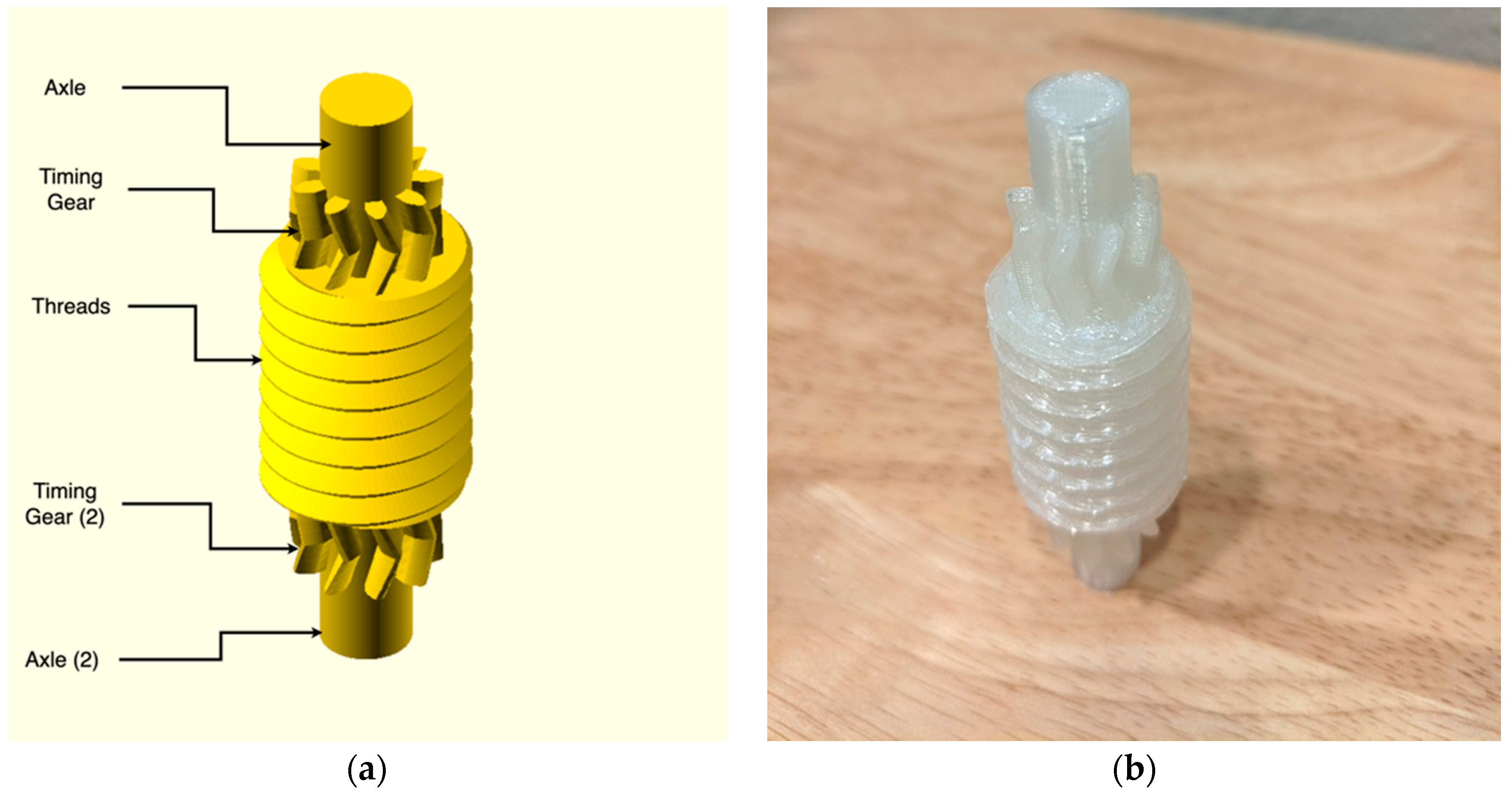
The central screw is the simplest component in the entire assembly. Figure A1a shows a finished and labeled central screw assembly. Table A3 provides all of the parameters for the central screw. The following sections will describe the operation of the OpenSCAD code for generating the central screw.
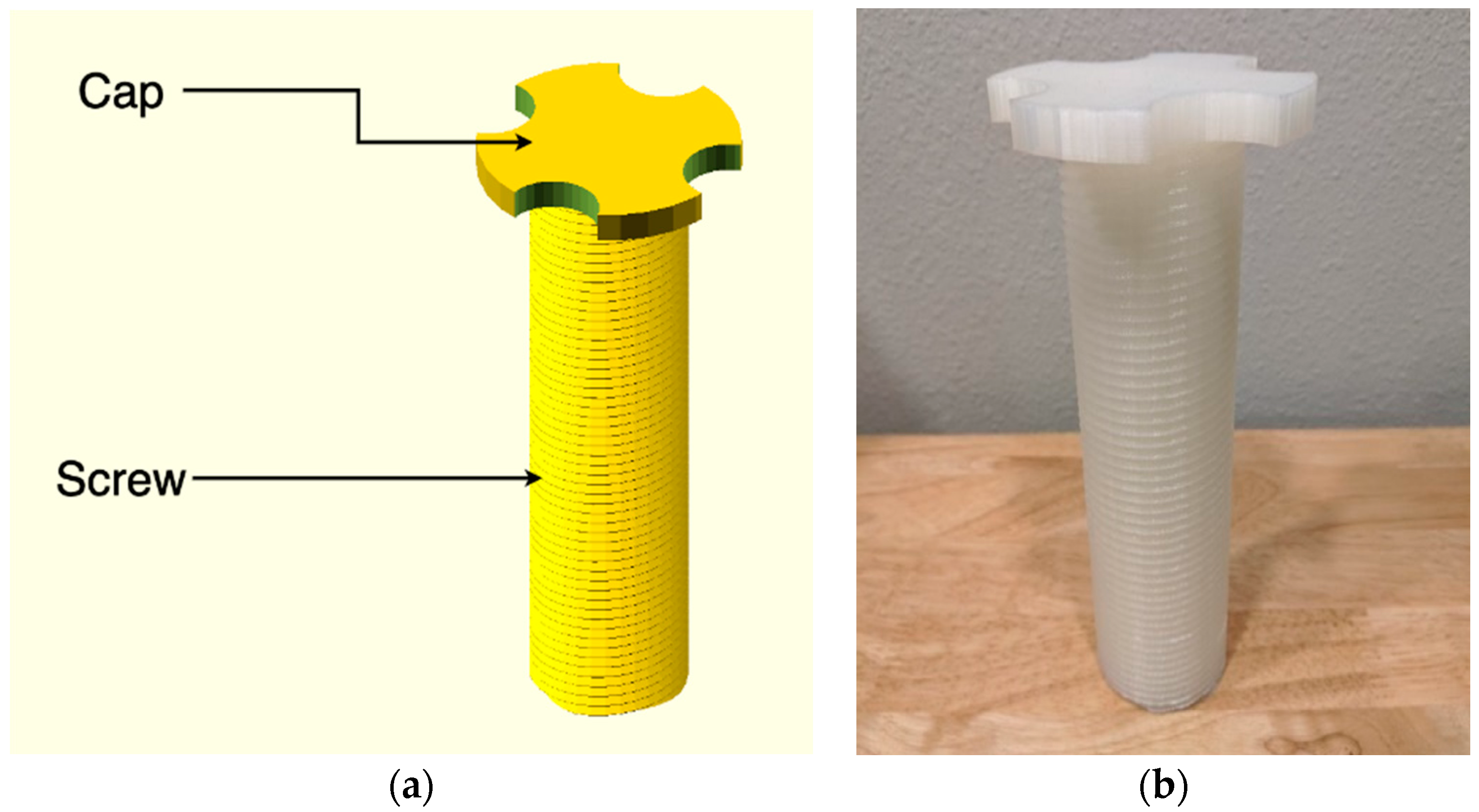
Figure A1.
(a) Finished and labeled rendering of the central screw assembly. Note that when printed, the cap would be placed on the build plate and the assembly would be flipped 180 degrees. (b) Three-dimensional (3D)-printed central screw assembly. Printed on an open source PrusaMK3S with natural PLA at 0.2 mm layer height.

Table A3.
OpenSCAD central screw parameters.
| Parameter | OpenSCAD Variable | Unit | Description |
|---|---|---|---|
| Screw | |||
| Screw Diameter | d_screw_eff | mm | Major diameter of the central screw |
| Screw Lead | l_screw_lead | mm | Lead of the central screw |
| Screw Thread Starts | n_screw_threads | Ea. | Number of thread starts in the central screw |
| Screw Length | l_screw_length | mm | Length of the central screw. Does not affect overall function |
| Screw Cap | |||
| Outer Diameter | d_cap_outer | mm | Outer diameter of screw cap |
| Cut circles diameter | d_cap_cut_temp | mm | Outer diameter of the circles used to cut holes into the cap |
| Cap thickness | l_cap_thickness | mm | Overall thickness of the cap |
| Cap Cut-ins | n_cap_cuts | Ea. | Number of cuts to be made into the cap |
As shown in Figure A1, the overall design of the central screw is simple. The design consists of a large, central, threaded rod with a cap at top. The cap serves two functions. One is to force a lower limit to the travel of the screw to prevent the screw from falling out of the assembly. The second is to allow the user to quickly turn the central screw if the need were to arise. This would be a quicker method of moving the screw than with the Planetary Roller Assembly.
The threaded rod of the central screw has the simplest external implementation. This is due to the use of the tsmthread4.scad developed by Dan Kirshner [78]. Using this thread library, the central threaded rod is a simple function call using the screw diameter (d_screw_eff), screw lead (l_screw_lead), screw thread starts (n_screw_threads), and screw length (l_screw_length). It is important to note that the screw diameter, screw lead, and screw thread starts are extremely important to the overall operation of the assembly. These parameters will be in all the major modules and must be the same across all of these modules.
The cap is a fairly simple construction. In OpenSCAD, it is implemented in its own module, which is then moved up to and attached (unioned) to the screw. The cap module generates one large central cylinder with the following parameters: outer diameter (d_cap_outer), cap thickness (l_cap_thickness). The outer diameter parameter defines the diameter of the cylinder while the cap thickness determines the cylinder height. This is the primary cylinder. Then, the cap module produces a cap cut-ins (n_cap_cuts) number of cylinders with a diameter of cut circles diameter (d_cap_cut_temp) and a height of cap thickness (l_cap_thickness). These cylinders are translated out to half of the diameter of the primary cylinder and then rotated around the primary cylinder. Finally, the periphery cylinders are subtracted from the primary cylinder to produce “cuts” into the primary cylinder that can be used to grasp and spin the central screw.
Appendix A.1.2. Rollers
The rollers are a more complex design and are a critical part of the entire assembly. The rollers transfer all of the axial forces exerted on the central screw to the nut. The rollers are also the primary method of rotating, and therefore actuating, the central screw when the nut is rotated. These design considerations imply that the rollers need to be robust while also minimizing rolling friction between themselves and the central screw. Figure A2a shows a rendered and labeled image of the roller and (b) shows the required parameters to be generated. The following section will discuss the design of the roller and the usage of the rollers OpenSCAD Module.
Figure A2.
(a) Finished and labeled rendering of the roller assembly. (b) Three-dimensional (3D)-printed roller assembly. Printed on an open source PrusaMK3S with natural PLA at 0.2 mm layer height. Printed in orientation shown with support material around bottom overhang.
Figure A2.
(a) Finished and labeled rendering of the roller assembly. (b) Three-dimensional (3D)-printed roller assembly. Printed on an open source PrusaMK3S with natural PLA at 0.2 mm layer height. Printed in orientation shown with support material around bottom overhang.

The rollers are designed with a central section of threads, gears on both the top and bottom of the roller, and an axle that extends through the roller and past the gears. However, the gears and threads do not intersect with each other as they do in the original patent. In the original patent, this was required due to manufacturing limitations; the manufacturer could not simply start and stop the threads along the stock and then hob gears out of it. The conventional manufacturer was forced to make the threads along the entire length of their stock and then hob gears into both ends of the threads, creating the intersecting gears and threads in the patent. For this design using more advanced AM, it was decided to try what the original patent could not, so the gears and threads were kept separate from each other.
The parameters for the OpenSCAD module can be seen in Table A4. Notice that the three primary design parameters (central screw lead, central screw thread starts, and central screw major diameter) are being used rather than the direct values for the roller. The values that the rollers use to generate geometry is calculated within the module and will be discussed later in this section.
Table A4.
OpenSCAD roller parameters.
| Parameter | OpenSCAD Variable | Unit | Description |
|---|---|---|---|
| Assembly Parameters | |||
| Screw Diameter | d_screw_eff | mm | Major diameter of the central screw |
| Screw Lead | l_screw_lead | mm | Lead of the central screw |
| Screw Thread Starts | n_screw_threads | Ea. | Number of thread starts in the central screw |
| Roller Parameters | |||
| Thread Length | l_screw_length | mm | Length of the threads on the rollers |
| Gear Module | h_gear_module | N/A | Module of the timing gears at the top and bottom of the rollers. Needs to be the same as the nut. |
| Gear Teeth Count | n_gear_teeth | Ea. | Number of teeth on the timing gears. Should be set so gears are roughly same diameter as rollers. |
| Gear Height | l_gear_face | mm | Height of gear faces on the timing gears. |
| Gear Pressure Angle | a_gear_press | ° | Pressure angle of the timing gear teeth. Needs to be the same as the pressure angle for the nut. |
| Gear Helix Angle | a_gear_helix | ° | Helical gear angle of the timing gears. Needs to be the same as the nut. |
| Axle Extension | l_axle_extension | mm | Extension of the axle past the gear faces. |
| Axle Radius | L_axle_radius | mm | Radius of the central axle. Note, does not have protective limits. |
As noted, not all of the variables used to generate the geometry of the rollers are defined directly by the user. A couple of the critical dimensions are calculated within the roller module code and are used by the rest of the code for geometry generation. These variables are outlined, along with the calculations to obtain them, in Table A5.
Table A5.
OpenSCAD variable and calculation for roller.
| OpenSCAD Variable | Unit | Calculation | Description |
|---|---|---|---|
| d_screw_eff | mm | d_screw_eff = d_central_screw / (n_central_screw_thread_starts − 2) | Major diameter of the roller screw |
| l_screw_pitch | mm | l_screw_lead = l_central_screw_lead / n_central_screw_thread_starts | Pitch of the roller screw |
| axle_length | mm | (l_screw_length+l_gear_face*2)+2 * l_axle_extension | Overall axle length |
These values combined create the rollers. The structure of the roller is constructed using a cylinder, one set of threads from tmsthreads, and two gears (of appropriate type) from Giertriebe. The central cylinder is constructed with a diameter specified by Axle Radius and uses axle_length for the overall height of the cylinder. The roller threads use the calculated value d_screw_eff for the major diameter of the threads with the pitched defined by l_screw_pitch. The overall length of the threads is defined by the user parameter, Thread Length. The standard and angle of the threads are hardcoded into the module; however, they may be changed by a user as long as those changes are made to the nut and central screw modules as well.
Appendix A.1.3. Outer Nut
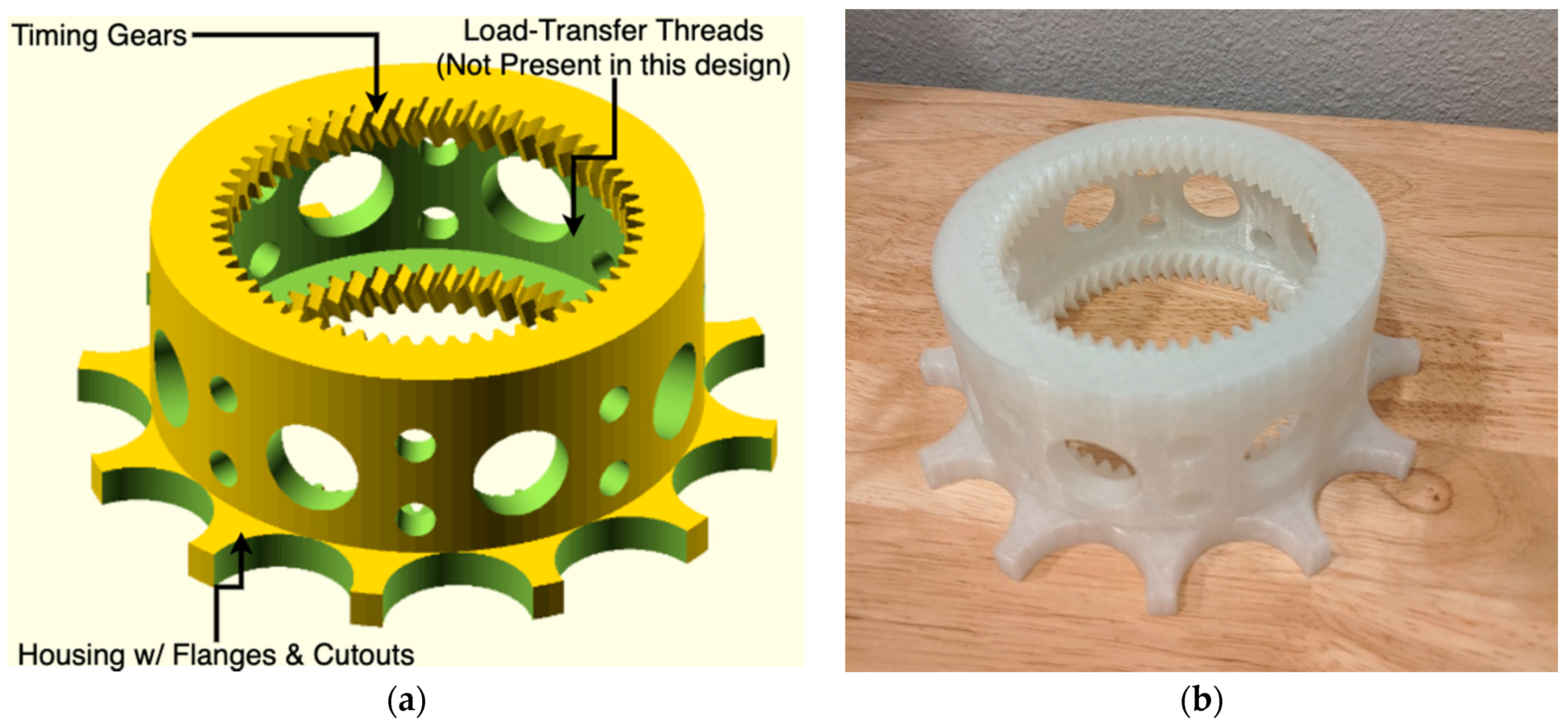
The outer nut utilizes a “carving” method of the inside of the nut. This is used to carve the shape of the outer nut into the external housing. That is, a positive image of the internal workings of the nut is created. Then, that image is subtracted from the housing of the outer nut. This method allows more flexibility in the shape and form of the housing. This image includes the timing gears and load-transfer threads, which mesh with the rollers. Figure A3a shows a labeled rendering of the outer nut with the printed output being show in (b).
Figure A3.
(a) Finished and labeled rendering of the outer nut assembly. (b) Three-dimensional (3D)-printed outer nut assembly. Printed on an open source PrusaMK3S with natural PLA at 0.2 mm layer height. Printed in shown orientation with support material on inner diameter to support ring gears.
Figure A3.
(a) Finished and labeled rendering of the outer nut assembly. (b) Three-dimensional (3D)-printed outer nut assembly. Printed on an open source PrusaMK3S with natural PLA at 0.2 mm layer height. Printed in shown orientation with support material on inner diameter to support ring gears.

The timing gears mesh with the rollers and prevent them from rotating out of sync with the rest of the system, which can cause binding of the threads. The threads, as the name implies, transfer the axial load from the rollers (which had a force induced on them by the central screw) into the nut. As noted in Figure A3a, these threads were not included for this design to simplify the construction and printing of the nut. This can be done because the timing gears are herringbone gears that can transfer and support some axial load. Similar to the separation of the timing gears and threads, which was done in the rollers, this method could not be accomplished in the original patent due to manufacturing limitations. AM methods allow the usage of these gears in the system and exclusion of the Load-Transfer threads.
The housing for the outer nut is a simple cylinder with flanges that can be pushed by hand. There are also a number of cut-outs in the housing that carve through the entire assembly. These reduce plastic use for the overall outer nut but can be excluded if desired.
In Table A6, the primary parameters for the outer nut are described.
Table A6.
OpenSCAD outer screw parameters.
| Parameter | OpenSCAD Variable | Unit | Description |
|---|---|---|---|
| Assembly Parameters | |||
| Screw Diameter | d_screw_eff | mm | Major diameter of the central screw |
| Screw Lead | l_screw_lead | mm | Lead of the central screw |
| Screw Thread Starts | n_screw_threads | Ea. | Number of thread starts in the central screw |
| Nut Parameters | |||
| Thread Length | l_screw_length | mm | Length of the threads on the nut |
| Ring Gear Module | h_ring_module | N/A | Module of the timing gears at the top and bottom of the rollers. Needs to be the same as the rollers. |
| Ring Gear Teeth Count | n_ring_teeth | Ea. | Number of teeth on the timing gears. Should be set so gears are roughly same diameter as rollers. |
| Ring Gear Height | l_ring_face | mm | Height of gear faces on the timing gears. |
| Ring Gear Pressure Angle | a_ring_press | ° | Pressure angle of the timing gear teeth. Needs to be the same as the pressure angle for the rollers. |
| Ring Gear Helix Angle | a_ring_helix | ° | Helical gear angle of the timing gears. Needs to be the same as the rollers. |
| Ring Gear Rim | d_ring_rim | mm | Rim of extra material around the timing gears. |
| Housing Parameters | |||
| Housing Flange Diameter | d_cap_outer | mm | Diameter of the outer housing flanges. |
| Flange Cut diameter | d_cap_cut_temp | mm | Diameter of the circles cut into the flanges. |
| Flange Thickness | l_cap_thickness | mm | Thickness of the flanges from the bottom of the assembly. |
| Number of Flanges | n_cap_cuts | Ea. | Number of cuts for flanges. |
The actual generation of the outer nut uses a few modules. The first generates the rings gears, one for the top, one for the bottom, as well as the inner cylinder. This inner cylinder is used to cut a hole into the large cylinder that forms the rest of the body. After this is complete, cylinders are used to cut the holes into the overall body. Finally, a hollowed cylinder is attached to the bottom, and the flanges are formed with repeating cylinders that orbit around the hollowed cylinder. Most of the actions use their own internal module, which then are used in conjunction to form the entire structure.
Appendix A.1.4. Spacer
The spacers (Figure A4) are a very simple construction that is used to maintain appropriate distance between the rollers as the operater. They prevent the rollers from shifting within the assembly. In many cases, these spacers were not needed and are excluded from the overall assembly.
Figure A4.
Finished and labeled rendering of the spacer.

The spacer design is simple, consisting of a cylinder with a clearance bore through the middle that accommodates the central screw assembly. Along the ring of the spacer are bore holes that act as simple bearings for the rollers. These bearings allow the rollers to roll and make slight shifts in angle while maintaining a safe distance between the rollers.
References
- Giotitsas, C. Open Source Agriculture: A Social Movement? In Open Source Agriculture: Grassroots Technology in the Digital Era; Giotitsas, C., Ed.; Palgrave Advances in Bioeconomy: Economics and Policies; Springer International Publishing: Cham, Germany, 2019; pp. 25–68. ISBN 978-3-030-29341-3. [Google Scholar]
- Meyer, M.; Pantazia, A. Making, Adapting, Sharing: Fabricating Open-Source Agricultural Tools. P2P Found. 2018. Available online: https://blog.p2pfoundation.net/making-adapting-sharing-fabricating-open-source-agricultural-tools/2018/07/06 (accessed on 6 May 2020).
- Lemmens, P. Deproletarianizing Agriculture—Recovering Agriculture from Agribusiness and the need for a Commons-Based, Open Source Agriculture. In Proceedings of the ISDA 2010, Montpellier, France, 28 June–1 July 2010; Coudel, E., Devautour, H., Soulard, C.-T., Hubert, B., Eds.; Cirad-Inra-SupAgro: Montpellier, France, 2010; p. 21. [Google Scholar]
- Nicolosi, G.; Ruivenkamp, G. Re-skilling the Social Practices: Open Source and Life–Towards a Commons-Based Peer Production in Agro-biotechnology? Sci. Eng. Ethics 2013, 19, 1181–1200. [Google Scholar] [CrossRef]
- Giotitsas, C. Beyond Open Source Agriculture. In Open Source Agriculture: Grassroots Technology in the Digital Era; Giotitsas, C., Ed.; Palgrave Advances in Bioeconomy: Economics and Policies; Springer International Publishing: Cham, Germany, 2019; pp. 133–139. ISBN 978-3-030-29341-3. [Google Scholar]
- Group Overview ‹ Open Agriculture (OpenAg). Available online: https://www.media.mit.edu/groups/open-agriculture-openag/overview/ (accessed on 6 May 2020).
- Harper, C. Open-Source Agriculture Initiative—Food for the Future? In LED Lighting for Urban. Agriculture; Kozai, T., Fujiwara, K., Runkle, E.S., Eds.; Springer: Singapore, 2016; pp. 37–46. ISBN 978-981-10-1848-0. [Google Scholar]
- GOAT—Gathering for Open Agricultural Technology. Available online: http://goatech.org/ (accessed on 6 May 2020).
- Sowe, S.K.; Parayil, G.; Sunami, A. Free and Open Source Software and Technology for Sustainable Development; United Nations University Press: Tokyo, Japan, 2012; ISBN 978-92-808-1217-6. [Google Scholar]
- Tsioumani, E.; Muzurakis, M.; Ieropoulos, Y.; Tsioumanis, A. Following the Open Source Trail Outside the Digital World: Open Source Applications in Agricultural Research and Development; Social Science Research Network: Rochester, NY, USA, 2015. [Google Scholar]
- Pearce, J.M. The case for open source appropriate technology. Environ. Dev. Sustain. 2012, 14, 425–431. [Google Scholar] [CrossRef] [Green Version]
- Raymond, E. The cathedral and the bazaar. Knowl. Technol. Policy 1999, 12, 23–49. [Google Scholar] [CrossRef]
- Bonaccorsi, A.; Rossi, C. Why Open Source software can succeed. Res. Policy 2003, 32, 1243–1258. [Google Scholar] [CrossRef] [Green Version]
- Lakhani, K.R.; von Hippel, E. How Open Source Software Works: “Free” User-to-User Assistance. In Produktentwicklung Mit Virtuellen Communities: Kundenwünsche Erfahren und Innovationen Realisieren; Herstatt, C., Sander, J.G., Eds.; Gabler Verlag: Wiesbaden, Germany, 2004; pp. 303–339. ISBN 978-3-322-84540-5. [Google Scholar]
- Söderberg, J. Hacking Capitalism: The Free and Open Source Software Movement; Routledge: London, UK, 2015; ISBN 978-1-135-91639-8. [Google Scholar]
- Bergquist, M.; Ljungberg, J. The power of gifts: Organizing social relationships in open source communities. Inf. Syst. J. 2001, 11, 305–320. [Google Scholar] [CrossRef]
- Pearce, J.M.; Mushtaq, U. Overcoming Technical Constraints for Obtaining Sustainable Development with Open Source Appropriate Technology. In Proceedings of the 2009 IEEE Toronto International Conference Science and Technology for Humanity (TIC-STH), Toronto, ON, Canada, 26–27 September 2009; pp. 814–820. [Google Scholar]
- Zelenika, I.; Pearce, J. Barriers to Appropriate Technology Growth in Sustainable Development. J. Sustain. Dev. 2011, 4, 12. [Google Scholar] [CrossRef]
- Hazeltine, B.; Bull, C. Appropriate Technology; Tools, Choices, and Implications, 1st ed.; Academic Press, Inc.: Cambridge, MA, USA, 1998; ISBN 978-0-12-335190-6. [Google Scholar]
- Rees, W.E. Understanding Sustainable Development. In Sustainable Development and The Future of Cities; Hamm, B., Muttagi, P.K., Eds.; Intermediate Technology Publications Limited: London, UK, 1998; pp. 19–42. [Google Scholar]
- Sianipar, C.P.M.; Yudoko, G.; Adhiutama, A.; Dowaki, K. Community Empowerment through Appropriate Technology: Sustaining the Sustainable Development. Procedia Environ. Sci. 2013, 17, 1007–1016. [Google Scholar] [CrossRef] [Green Version]
- Pearce, J.; Albritton, S.; Grant, G.; Steed, G.; Zelenika, I. A new model for enabling innovation in appropriate technology for sustainable development. Sustain. Sci. Pract. Policy 2012, 8, 42–53. [Google Scholar] [CrossRef]
- Zelenika, I.; Pearce, J.M. Innovation through collaboration: Scaling up solutions for sustainable development. Environ. Dev. Sustain. 2014, 16, 1299–1316. [Google Scholar] [CrossRef] [Green Version]
- Zelenika, I.; Pearce, J.M. The Internet and other ICTs as tools and catalysts for sustainable development: Innovation for 21st century. Inf. Dev. 2013, 29, 217–232. [Google Scholar] [CrossRef]
- Parker, M.; Cheney, G.; Fournier, V.; Land, C. The Routledge Companion to Alternative Organization; Routledge: London, UK, 2014; ISBN 978-1-135-00539-9. [Google Scholar]
- Gupta, A.K. From Sink to Source: The Honey Bee Network Documents Indigenous Knowledge and Innovations in India. Innov. Technol. Gov. Glob. 2006, 1, 49–66. [Google Scholar] [CrossRef]
- Smith, A.; Fressoli, M.; Thomas, H. Grassroots innovation movements: Challenges and contributions. J. Clean. Prod. 2014, 63, 114–124. [Google Scholar] [CrossRef]
- Abrol, D.; Gupta, A. Understanding the diffusion modes of grassroots innovations in India: A study of Honey Bee Network supported innovators. Afr. J. Sci. Technol. Innov. Dev. 2014, 6, 541–552. [Google Scholar] [CrossRef] [Green Version]
- Pattnaik, B.K.; Dhal, D. Mobilizing from appropriate technologies to sustainable technologies based on grassroots innovations. Technol. Soc. 2015, 40, 93–110. [Google Scholar] [CrossRef]
- Harper, C.; Siller, M. OpenAG: A Globally Distributed Network of Food Computing. IEEE Pervasive Comput. 2015, 14, 24–27. [Google Scholar] [CrossRef]
- Boanos, A.; Mothukuri, A.S.; Goettsch, K.A.; Bastola, D.K. Investigation and Utilization of Personal Food Computers for Research in Drug Development and Biomedicine. In Proceedings of the 2017 IEEE International Conference on Bioinformatics and Biomedicine (BIBM), Kansas City, MO, USA, 13–16 November 2017; pp. 2229–2231. [Google Scholar]
- Jakubowski, M. Open Source Ecology. In Kunst, Krise, Subversion; Bandi, N., Kraft, M.G., Lasinger, S., Eds.; Transcript Verlag: Bielefeld, Germany, 2012; ISBN 978-3-8394-1962-5. [Google Scholar]
- Moritz, M.; Redlich, T.; Grames, P.P.; Wulfsberg, J.P. Value Creation in Open-Source Hardware Communities: Case Study of Open Source Ecology. In Proceedings of the 2016 Portland International Conference on Management of Engineering and Technology (PICMET), Portland, OR, USA, 4–8 September 2016; pp. 2368–2375. [Google Scholar]
- Osunyomi, B.D.; Redlich, T.; Wulfsberg, J.P. Could open source ecology and open source appropriate technology be used as a roadmap from technology colony? Int. J. Technol. Learn. Innov. Dev. 2016, 8, 265. [Google Scholar] [CrossRef]
- Macul, V.; Rozenfeld, H. How an Open Source Design Community Works: The case of Open Source Ecology. Available online: https://www.designsociety.org/publication/37745/HOW+AN+OPEN+SOURCE+DESIGN+COMMUNITY+WORKS%3A+THE+CASE+OF+OPEN+SOURCE+ECOLOGY (accessed on 6 May 2020).
- Pearce, J.M.; Morris Blair, C.; Laciak, K.J.; Andrews, R.; Nosrat, A.; Zelenika-Zovko, I. 3-D Printing of Open Source Appropriate Technologies for Self-Directed Sustainable Development. J. Sustain. Dev. 2010, 3, 17. [Google Scholar] [CrossRef] [Green Version]
- Canessa, E. Open Book on “Low-cost 3D Printing for Science, Education and Sustainable Development”. Available online: http://sdu.ictp.it/3D/book.html (accessed on 6 May 2020).
- Sells, E.; Bailard, S.; Smith, Z.; Bowyer, A.; Olliver, V. RepRap: The Replicating Rapid Prototyper: Maximizing Customizability by Breeding the Means of Production. In Handbook of Research in Mass Customization and Personalization; World Scientific Publishing Company: Singapore, 2009; pp. 568–580. ISBN 978-981-4280-25-9. [Google Scholar]
- Jones, R.; Haufe, P.; Sells, E.; Iravani, P.; Olliver, V.; Palmer, C.; Bowyer, A. RepRap—The replicating rapid prototyper. Robotica 2011, 29, 177–191. [Google Scholar] [CrossRef] [Green Version]
- Kentzer, J.; Koch, B.; Thiim, M.; Jones, R.W.; Villumsen, E. An Open Source Hardware-Based Mechatronics Project: The Replicating Rapid 3-D Printer. In Proceedings of the 2011 4th International Conference on Mechatronics (ICOM), Kuala Lumpur, Malaysia, 17–19 May 2011; pp. 1–8. [Google Scholar]
- Bowyer, A. 3D Printing and Humanity’s First Imperfect Replicator. 3D Print. Addit. Manuf. 2014, 1, 4–5. [Google Scholar] [CrossRef]
- Rundle, G. A Revolution in the Making; Simon and Schuster: New York, NY, USA, 2014; ISBN 978-1-922213-48-8. [Google Scholar]
- King, D.L.; Babasola, A.; Rozario, J.; Pearce, J.M. Mobile Open-Source Solar-Powered 3-D Printers for Distributed Manufacturing in Off-Grid Communities. Chall. Sustain. 2014, 2, 18–27. [Google Scholar] [CrossRef]
- Gwamuri, J.; Franco, D.; Khan, K.Y.; Gauchia, L.; Pearce, J.M. High-Efficiency Solar-Powered 3-D Printers for Sustainable Development. Machines 2016, 4, 3. [Google Scholar] [CrossRef]
- Birtchnell, T.; Hoyle, W. 3D Printing for Development in the Global South: The 3D4D Challenge; Springer: Berlin/Heidelberg, Germany, 2014; ISBN 978-1-137-36566-8. [Google Scholar]
- Zhong, S.; Rakhe, P.; Pearce, J.M. Energy Payback Time of a Solar Photovoltaic Powered Waste Plastic Recyclebot System. Recycling 2017, 2, 10. [Google Scholar] [CrossRef]
- Zhong, S.; Pearce, J.M. Tightening the loop on the circular economy: Coupled distributed recycling and manufacturing with recyclebot and RepRap 3-D printing. Resour. Conserv. Recycl. 2018, 128, 48–58. [Google Scholar] [CrossRef] [Green Version]
- Wittbrodt, B.T.; Glover, A.G.; Laureto, J.; Anzalone, G.C.; Oppliger, D.; Irwin, J.L.; Pearce, J.M. Life-cycle economic analysis of distributed manufacturing with open-source 3-D printers. Mechatronics 2013, 23, 713–726. [Google Scholar] [CrossRef] [Green Version]
- Petersen, E.E.; Pearce, J. Emergence of Home Manufacturing in the Developed World: Return on Investment for Open-Source 3-D Printers. Technologies 2017, 5, 7. [Google Scholar] [CrossRef] [Green Version]
- Petersen, E.E.; Kidd, R.W.; Pearce, J.M. Impact of DIY Home Manufacturing with 3D Printing on the Toy and Game Market. Technologies 2017, 5, 45. [Google Scholar] [CrossRef]
- Ishengoma, F.R.; Mtaho, A.B. 3D Printing: Developing Countries Perspectives. Int. J. Comput. Appl. 2014, 104, 30–34. [Google Scholar] [CrossRef]
- Pearce, J.M. Applications of Open Source 3-D Printing on Small Farms. Org. Farming 2015, 1, 19–35. [Google Scholar] [CrossRef] [Green Version]
- Wittbrodt, B.T.; Squires, D.A.; Walbeck, J.; Campbell, E.; Campbell, W.H.; Pearce, J.M. Open-Source Photometric System for Enzymatic Nitrate Quantification. PLoS ONE 2015, 10, e0134989. [Google Scholar] [CrossRef]
- Wijnen, B.; Anzalone, G.C.; Pearce, J.M. Open-source mobile water quality testing platform. J. Water Sanit. Hyg. Dev. 2014, 4, 532–537. [Google Scholar] [CrossRef]
- Tymrak, B.M.; Kreiger, M.; Pearce, J.M. Mechanical properties of components fabricated with open-source 3-D printers under realistic environmental conditions. Mater. Des. 2014, 58, 242–246. [Google Scholar] [CrossRef] [Green Version]
- Wittbrodt, B.; Pearce, J.M. The effects of PLA color on material properties of 3-D printed components. Addit. Manuf. 2015, 8, 110–116. [Google Scholar] [CrossRef] [Green Version]
- Fernandez-Vicente, M.; Calle, W.; Ferrandiz, S.; Conejero, A. Effect of Infill Parameters on Tensile Mechanical Behavior in Desktop 3D Printing. 3D Print. Addit. Manuf. 2016, 3, 183–192. [Google Scholar] [CrossRef]
- Tanikella, N.G.; Wittbrodt, B.; Pearce, J.M. Tensile strength of commercial polymer materials for fused filament fabrication 3D printing. Addit. Manuf. 2017, 15, 40–47. [Google Scholar] [CrossRef] [Green Version]
- Kung, C.; Kuan, H.-C.; Kuan, C.-F. Evaluation of Tensile Strength of 3D Printed Objects with FDM Process on RepRap Platform. In Proceedings of the 2018 1st IEEE International Conference on Knowledge Innovation and Invention (ICKII), Jeju Island, Korea, 23–27 July 2018; pp. 369–372. [Google Scholar]
- Reich, M.J.; Woern, A.L.; Tanikella, N.G.; Pearce, J.M. Mechanical Properties and Applications of Recycled Polycarbonate Particle Material Extrusion-Based Additive Manufacturing. Materials 2019, 12, 1642. [Google Scholar] [CrossRef] [PubMed] [Green Version]
- Strandgren, C.B. Screw-Threaded Mechanism. U.S. Patent 2,683,379 A, 13 July 1954. [Google Scholar]
- RollerScrew. (1.0), TheJLo. Available online: https://github.com/TheJLo/RollerScrew (accessed on 4 February 2020).
- LulzBot TAZ 6|LulzBot. Available online: https://www.lulzbot.com/store/printers/lulzbot-taz-6 (accessed on 22 April 2020).
- Susko, A.Q.; Gilbertson, F.; Heuschele, D.J.; Smith, K.; Marchetto, P. An Automatable, Field Camera Track System for Phenotyping Crop Lodging and Crop Movement. HardwareX 2018, 4, e00029. [Google Scholar] [CrossRef]
- Jo Heuschele, D.; Wiersma, J.; Reynolds, L.; Mangin, A.; Lawley, Y.; Marchetto, P. The Stalker: An Open Source Force Meter for Rapid Stalk Strength Phenotyping. HardwareX 2019, 6, e00067. [Google Scholar] [CrossRef]
- Broekman, A.; Steyn, W.J.; Steyn, J.L.; Bill, M.; Korsten, L. SmAvo and SmaTo: A Fruity Odyssey of Smart Sensor Platforms in Southern Africa. HardwareX 2020, 8, e00156. [Google Scholar] [CrossRef]
- Spinelli, G.M.; Gottesman, Z.L.; Deenik, J. A Low-Cost Arduino-Based Datalogger with Cellular Modem and FTP Communication for Irrigation Water Use Monitoring to Enable Access to CropManage. HardwareX 2019, 6, e00066. [Google Scholar] [CrossRef]
- Bentancor, M.; Vidal, S. Programmable and Low-Cost Ultraviolet Room Disinfection Device. HardwareX 2018, 4, e00046. [Google Scholar] [CrossRef]
- Sun, J.; Zhou, W.; Huang, D.; Fuh, J.Y.H.; Hong, G.S. An Overview of 3D Printing Technologies for Food Fabrication. Food Bioprocess. Technol. 2015, 8, 1605–1615. [Google Scholar] [CrossRef]
- Nachal, N.; Moses, J.A.; Karthik, P.; Anandharamakrishnan, C. Applications of 3D Printing in Food Processing. Food Eng. Rev. 2019, 11, 123–141. [Google Scholar] [CrossRef]
- Skrzypczak, N.G.; Tanikella, N.G.; Pearce, J.M. Open Source High-Temperature RepRap for 3-D Printing Heat-Sterilizable PPE and Other Applications. HardwareX 2020, 8, e00130. [Google Scholar] [CrossRef] [PubMed]
- Yanisky-Ravid, S.; Kwan, K.S. 3D Printing the Road Ahead: The Digitization of Products When Public Safety Meets Intellectual Property Rights—A New Model. Cardozo L. Rev. 2016, 38, 921. [Google Scholar]
- Powell, A. Democratizing production through open source knowledge: From open sof.tware to open hardware. Media Cult. Soc. 2012, 34, 691–708. [Google Scholar] [CrossRef] [Green Version]
- Gibb, A.; Abadie, S. Building Open Source Hardware: DIY Manufacturing for Hackers and Makers; Pearson Education: London, UK, 2014; ISBN 978-0-321-90604-5. [Google Scholar]
- Oberloier, S.; Pearce, J.M. General Design Procedure for Free and Open-Source Hardware for Scientific Equipment. Designs 2018, 2, 2. [Google Scholar] [CrossRef] [Green Version]
- Bonvoisin, J.; Molloy, J.; Haeuer, M.; Wenzel, T. Standardisation of practices in Open Source Hardware. arXiv 2020, arXiv:2004.07143. [Google Scholar] [CrossRef]
- Kintel, M. OpenSCAD. 2020. Available online: https://www.openscad.org/index.html (accessed on 4 February 2020).
- Kirshner, D. Thread-Drawing Modules for OpenSCAD. 2020. Available online: https://dkprojects.net/openscad-threads (accessed on 27 May 2020).
- Janssen, J. Beispiele Für Jedes Modul Befinden Sich Auskommentiert am Ende Dieser Datei. 2020. Available online: https://www.thingiverse.com/thing:1604369 (accessed on 27 May 2020).
- Original Prusa i3 MK3 Kit. Available online: https://shop.prusa3d.com/en/3d-printers/180-original-prusa-i3-mk3-kit.html?gclid=EAIaIQobChMI37S_yc7S6QIVJBh9Ch1-bgDvEAAYASAAEgKIlfD_BwE (accessed on 27 May 2020).
Figure 1.
Fully 3D-printed and assembled roller screw assembly. Printed on an open source Prusa Mk3S in natural PLA at 0.2 mm layer height.
Figure 1.
Fully 3D-printed and assembled roller screw assembly. Printed on an open source Prusa Mk3S in natural PLA at 0.2 mm layer height.

Figure 2.
HX711 loadcell wiring diagram, courtesy of sparkfun.com.

Figure 3.
Image of 3D-printed polyethylene terephthalate glycol (PETG) roller screw during testing (left) and load cell with a push plate that was inserted into the test stand assembly (right).
Figure 3.
Image of 3D-printed polyethylene terephthalate glycol (PETG) roller screw during testing (left) and load cell with a push plate that was inserted into the test stand assembly (right).

Figure 4.
Image of direct press screw test assembly.

Figure 5.
Maximum force output of planetary roller screw actuated by hand. Samples captured every 0.1 s.
Figure 5.
Maximum force output of planetary roller screw actuated by hand. Samples captured every 0.1 s.

Figure 6.
Planetary roller screw loading profile with quarter-turn rotations of the collar.

Figure 7.
Direct screw press applied force as a function of time.

Figure 8.
Average force exerted by roller screw onto load cell per 90-degree rotation.

Figure 9.
Schematic of roller encapsulation method using “Angled” gears.

Table 1.
Primary functional parameters of a planetary roller screw.
| Parameter | Variable | Units | Description |
|---|---|---|---|
| Central Screw Lead | Linear distance traversed by the central screw per rotation of that central screw | ||
| Central Screw Thread Starts | Each | The number of thread starts on the central screw | |
| Central Screw Major Diameter | mm | The major diameter of the central screw |
Table 2.
Resulting functional variables from primary parameters.
| Component | Variable | Relationship | Units |
|---|---|---|---|
| Outer Nut | mm | ||
| Roller Diameter | mm |
Table 3.
Necessary mechanical parameters for constraining the planetary roller screw.
| Parameter | Variable | Units | Description |
|---|---|---|---|
| Assembly Height | mm | Linear height of the entire planetary roller screw assembly | |
| Number of Rollers | Each | The number of rollers to place in the assembly. Limited by the diameter of the rollers. Need at least 3. | |
| Timing Gear Height | mm | Linear height of the internal timing gears used on the nut and rollers. | |
| Timing Gear Module | Each | The metric module of the timing gears. Larger values correspond to larger gear teeth. Has no effect on gear ratios. | |
| Timing Gear Helical Angle | ° | Angle of the gear teeth from purely vertical. | |
| Timing Gear Tooth Shape | N/A | Standard shape of gear teeth such as Convolute. | |
| Thread Standard | N/A | Thread standard used such as ACME Square or UTS. | |
| Roller Axle Length | mm | Linear length of the axles extending from the tops and bottoms of the rollers. |
Table 4.
BOM of roller screw assembly.
| Name | Qty | Image |
|---|---|---|
| Outer Nut | 1 |  |
| Central Screw (Printed 180 degrees about x-axis) | 1 |  |
| Roller | 4 |  |
| Spacer | 2 |  |
Table 5.
BOM of test stand assembly.
| Name | Qty | Image |
|---|---|---|
| Top Retainer | 1 |  |
| Alternate Top Retainer (for direct screw press test) | 1 |  |
| Bottom Retainer | 1 |  |
| Slotted Brackets | 4 |  |
| Slot Anchor | 4 |  |
| Load Cell Top Plate Screw (Printed 180 degrees about x-axis) | 1 |  |
| Load Cell Bottom Plate Screw (Printed 180 degrees about x-axis) | 1 |  |
Table 6.
Test materials.
| Name | Description | Material | Image |
|---|---|---|---|
| Roller screw assembly | Unit under test. Mechanical system inserted into test rig assembly. Default high-detail print settings used in TAZ6 3D printer. | 3D-printed PETG (PLA Shown) |  |
| Test Stand Assembly | Encompasses roller screw and holds S-type load sensor in fixed position during use. Default high-detail print settings used in TAZ6 3D printer. Filament profile varied on brand. PETG version of the unit under test is shown. | 3D-printed PETG |  |
| S-Type load cell | Measures compression via change in resistance on strain gauge. Rated to 100 kg. Requires calibration prior to use. | Metal, purchased from Amazon.com |  |
| SparkFun HX711 Load Amplifier | Amplifies measured resistance in load cell to be read by Arduino. Must be soldered to load cell wires. Match wire color to color name on board. | PCB, purchased from Amazon.com |  |
| Arduino | Microcontroller used to run load sensor code. Mount onto breadboard and make connections with jumpers for ease of use. | PCB, purchased from Amazon.com |  |
Table 7.
Calculated pressure created by rotation of roller screw mechanism onto load cell.
| Angle (deg) | Pressure (kPa) |
|---|---|
| 90 | 27.09 |
| 180 | 162.78 |
| 270 | 276.86 |
| 360 | 363.45 |
| 450 | 428.28 |
Publisher’s Note: MDPI stays neutral with regard to jurisdictional claims in published maps and institutional affiliations. |
© 2021 by the authors. Licensee MDPI, Basel, Switzerland. This article is an open access article distributed under the terms and conditions of the Creative Commons Attribution (CC BY) license (https://creativecommons.org/licenses/by/4.0/).
Share and Cite
MDPI and ACS Style
Guadagno, M.C.; Loss, J.M.; Pearce, J.M. Open Source 3D-Printable Planetary Roller Screw for Food Processing Applications. Technologies 2021, 9, 24. https://0-doi-org.brum.beds.ac.uk/10.3390/technologies9020024
AMA Style
Guadagno MC, Loss JM, Pearce JM. Open Source 3D-Printable Planetary Roller Screw for Food Processing Applications. Technologies. 2021; 9(2):24. https://0-doi-org.brum.beds.ac.uk/10.3390/technologies9020024
Chicago/Turabian StyleGuadagno, Marcello C., Jacob M. Loss, and Joshua M. Pearce. 2021. "Open Source 3D-Printable Planetary Roller Screw for Food Processing Applications" Technologies 9, no. 2: 24. https://0-doi-org.brum.beds.ac.uk/10.3390/technologies9020024
Note that from the first issue of 2016, this journal uses article numbers instead of page numbers. See further details here.