1. Introduction
Thermoplastic polymers and their composites exhibit some distinctive properties such as lightweight and corrosion resistance, which represent a significant advantage when compared to other classes of materials, e.g., metals [
1,
2]. However, the properties provided by metallic coatings are required in many industrial sectors to improve, for example, their aesthetic appearance and abrasion resistance [
3,
4]. Moreover, metallic properties can be essential for advanced technological applications, such as electronic fields [
5]. In all these applications, the possibility of metalizing plastics has paved the way for new applications for polymer-based materials, reducing the costs and combining polymer advantages with metal properties, such as abrasion resistance and conductivity [
6].
The main metallization techniques that are currently used are electro-deposition [
7], electroless plating [
8], spray techniques [
3,
9], and physical vapor deposition (PVD) [
10]. Among these technologies, sputtering PVD can be considered a suitable technique for plastic substrates because low temperatures can be reached during the deposition, according to the depositing materials, thus preventing polymer degradation [
11]. Other attractive advantages of sputtering PVD processes are (a) the capability of covering corners uniformly; (b) the possibility to easily deposit metal alloys by a proper choice of the target composition [
12]; and (c) the elimination of dangerous chemicals used in other conventional metallization techniques, making this method an environmentally friendly surface treatment [
13].
Recently, several studies were performed to explore the opportunity to cover 3D-printed structures with metallic coatings for different purposes, such as the achievement of a good level of conductivity for rapid-prototyped polymers [
14], the fabrication of 3D-printed helical and spiral antennas [
15,
16], and the development of electroluminescent devices [
17]. For 3D-printed parts, the presence of a metallic coating enables the improvement of material properties, such as aesthetics, while also changing the user perception of 3D-printed polymers [
13,
18]. According to the metal deposited to produce the coating, an enhancement of mechanical strength can be achieved, as well as a good level of abrasion resistance and environmental resistance [
19].
In this work, the metallization of fused filament fabrication (FFF) components through a sputtering PVD route was explored to assess the level of aesthetic appearance and geometric accuracy obtained after a chromium coating sputtering deposition as a function of different 3D printing materials and parameters used. For this purpose, a finishing torture test 3D model was designed and 3D-printed with thermoplastics and polymer composites. Different thermoplastic materials were selected to explore the capability to metalize different 3D-printable materials with a wide range of characteristics. This will pave the way for the 3D printing of other polymer-based materials and subsequent chromium metallization to improve the surface finishes of additive manufactured products and expand the range of new potential applications.
2. Materials and Methods
The materials for 3D printing were purchased in the form of filaments and used as-is. Polylactic acid (PLA) filament was supplied by Prusa Polymers a.s., Prague, Czech Republic, with the commercial name Prusament PLA (purchased from Prusa Research a.s., Prague, Czech Republic). Acrylonitrile styrene acrylate (ASA) filament was supplied by FormFutura B.V., Nijmegen, Netherlands, with the commercial name ApolloX (local distributor: Conrad Electronic Italia S.r.l., Bollate, Italy). Polycarbonate and acrylonitrile butadiene styrene copolymer (PC-ABS) filaments were supplied by Ciceri de Mondel S.r.l., Ozzero, Italy, with the commercial name FILOALFA® PC-ABS (local distributor: Mega 3D, Cassano d’Adda, Italy). Co-polyester filament made with Amphora HT5300 polymer (Eastman Chemical Company, Kingsport, TN, USA) was supplied by colorFabb B.V., Belfeld, Netherlands, with the commercial name colorFabb_HT, hereinafter called HT-PE (local distributor: Mega 3D, Cassano d’Adda, Italy). Composite co-polyester filament made with Amphora AM1800 polymer (Eastman Chemical Company, Kingsport, TN, USA) and 20 wt% of carbon fibers were supplied by colorFabb B.V., Belfeld, Netherlands, with the commercial name colorFabb XT-CF20, hereinafter called XT-PE-CF20 (local distributor: Mega 3D, Cassano d’Adda, Italy).
Tensile tests were performed by means of a Zwick Roell Z010 (ZwickRoell GmbH & Co. KG, Ulm, Germany) with a 10 kN cell load. For the tests, the ASTM standard test method D3039/D3039M-17 (2017) was adopted [
20]. Following the requirements of the standard test method, a testing speed of 2 mm/min was selected, and the specimen dimensions were defined accordingly. The specimens had a constant rectangular cross-section, a width of 10 mm, and a thickness of 2.4 mm. A gripping length of 30 mm was employed, without the use of tabs, and the gauge length was 20 mm. From the standard test method, the length of the specimens was defined according to the following requirements: 2 times the gripping length + 2 times the width + gauge length, resulting in a final length of 100 mm. A total of 5 specimens were tested, and the mechanical properties were evaluated from the stress–strain curve obtained from the tests. Finally, the mean values and the standard error were evaluated.
Differential scanning calorimetry analysis was performed to measure the glass transition temperature (Tg) of the 3D printing filaments. The tests were performed with a Mettler-Toledo DSC/823e (Mettler Toledo, Columbus, OH, USA) in a N2 atmosphere. The heating ramp was set from −50 °C to 300 °C with a 20 °/min of heating rate, except for HT-PE, which was analyzed with a heating ramp from 25 °C to 300 °C at 20 °/min heating rate.
Tensile test specimens and the 3D model of the torture test were designed using Fusion 360 (Autodesk, San Rafael, CA, USA) CAD software. Complex surfaces of the 3D model were previously designed with the “Grasshopper” plugin of Rhinoceros (Robert McNeel & Associates, Seattle, WA, USA) and afterward integrated into the 3D model with Fusion 360.
Both the tensile specimens and the torture test samples were 3D printed with a Prusa i3 MK3S FDM 3D printer (Prusa Research a.s., Prague, Czech Republic). Tensile specimens Gcodes were created with Ultimaker Cura 3.6.0 slicing software (Ultimaker B.V., Utrecht, The Netherlands). Specimens were produced without perimeters or top and bottom layers. Moreover, 100% infill was set with a raster angle equal to 0° or 90°, compared to the overall length of the specimen. Torture tests Gcodes were created with Slic3r PE 1.41.3 slicing software (Prusa Research a.s., Prague, Czech Republic). Torture tests were 3D printed with 2 perimeters, 4 top and bottom layers, and 20% infill. Other material-specific 3D printing parameters are reported in
Table 1. As indicated in
Table 1 by the bed adhesion parameter, the 3D printing was performed with both a paper tape and a brim, which is a layer of the material that extends along the print bed from the edges of the 3D prints for PC-ABS, HT-PE, and XT-PE-CF20 samples. The presence of these two factors was needed for these materials to improve the adhesion of the 3D-printed objects to the printing surface and reduce the deformation in the final samples.
After visual inspection of the 3D-printed torture test samples, the chromium layer deposition was carried out through a PVD sputtering proprietary process from Green Coat S.r.l., San Benedetto Po, Italy. During this process, a range of temperatures from 20 to 60 °C can be reached. A UV-curable acrylic-based primer (UNILAC UV BC 05 from Cromogenia-Units S.A., Barcelona, Spain) was deposited onto the surface with a thickness of 70–80 µm before the PVD sputtering. Such values of primer thickness were chosen to assure a good leveling of the surface roughness present on the 3D parts. Before the primer application, the samples were cleaned with an isopropyl alcohol moistened cloth followed by a drying time of 10 min at room temperature. The samples were fixed on a rotational jig to assure the coating of all the surfaces of the samples. Firstly, the liquid primer deposition was carried out with anthropomorphic robots, which sprayed the UV-curable solventless primer to the samples with a rotary cup spinning at 25,000 rpm to achieve the atomization of primer. After the application, the primer UV-curing was performed, using 26 mercury vapor lamps with a 10” bulb and a peak irradiance of 500 mW/cm2. The total duration of the UV curing was about 2 min. The jig then entered the in-line metallization system where oxygen plasma provided the surface activation before the chromium layer deposition. The plasma treatment was performed for 90 s with an O2 flow of 700 sccm, an electrode power of 4 kW, and a rotation speed of 5 rpm. A thin layer of chromium was then deposited through the PVD magnetron sputtering process with a power of 10 kW for each cathode. The sputtering process was carried out at a pressure of 1.5 × 10⁻³ mbar with a constant argon flow of 600 sccm. The total duration of the deposition was 16 min. The expected chromium layer thickness with these parameters is 200 nm. The samples were then supplied by Green Coat S.r.l. for further investigations after the metallization process. The planar specimen surface roughness was measured by means of a laser profilometer (UBM). The roughness tests were performed along five different lines for each planar substrate. The point density of the measure was 500 points/mm, and the roughness values were reported in terms of the root mean square roughness (Rq). The cost analysis was performed and provided by Green Coat S.r.l.
3. Results and Discussion
3.1. Material Characterization
The 3D-printed thermoplastic polymers and composite were characterized to identify possible applications based on the thermal and mechanical properties. DSC analysis was useful to evaluate the maximum working temperature, based on the T
g. To prevent deformations of the 3D objects, thermal transitions during the metallization process are to be avoided. Consequently, higher T
g polymers are less prone to further deformations or warping after the 3D-printing process. In fact, residual thermal stresses are commonly produced during the fused filament fabrication (FFF) process, especially with low-cost desktop 3D printers, and residual thermal stresses may cause deformations or warping. As shown in
Table 2, all the materials, except for PLA, have a T
g higher than 60 °C, which approximately is the maximum temperature reached during metallization through PVD sputtering of chromium. Two glass transition temperatures were identified for ASA and PC-ABS, due to the different polymer phases, which are intrinsically present in these materials. Indeed, the
Tg_1 and
Tg_2 present in the PC-ABS sample can be attributed to the presence of separate phases composed of polycarbonate and poly-acrylonitrile/styrene, respectively. Concerning ASA glass transitions, the
Tg_2 is due to the presence of polyacrylonitrile and polystyrene phases. The lower value of T
g, i.e., 83 °C, can be related to the presence of additives aimed at improving the flowing behavior, thermal stability, and interlayer adhesion as reported by the producer [
21,
22]. Among the investigated materials, PC-ABS and HT-PE showed the highest values of T
g, higher than 100 °C. Consequently, no deformations are expected due to stress relaxation during the metallization process for these materials. On the contrary, 3D parts produced with PLA are prone to deformations and warping since the material T
g can be reached during the metallization process. Regardless, the exact temperature trend during the metallization process is unknown; considerations about the effects of the metallization process on the samples will be later discussed in
Section 3.3.
Table 3 shows the results of the mechanical tests. As described in the Materials and Methods section, specimens for tensile tests were produced with two different raster angles. The parts produced with the FFF process have anisotropic mechanical properties [
24,
25]. Consequently, the results of the tensile tests of the two sets of specimens are useful for the evaluation of 3D-printed material anisotropy. As shown in
Table 3, specimens with a raster angle equal to 0° show overall higher mechanical properties. Excluding PLA specimens, the materials under investigation exhibited a yield point when produced with this raster angle. On the contrary, all the materials showed a brittle behavior with no yield points when a raster angle of 90° was used. Moreover, the strain at break was lower than the strain at yield of the same material 3D printed with a 0° raster angle. This result could be related to different alignments and concentrations of defects produced during the FFF process. Small voids are commonly found between deposited strands of materials [
26,
27]. Considering specimens with 0° raster angles, the voids will be present between material strands aligned to the tensile direction. Consequently, the strands will sustain the tensile load. Otherwise, with a 90° raster angle, voids between strands will concentrate in transversal planes with respect to the tensile direction, creating weak surfaces between the strands.
PC-ABS and HT-PE, which were 3D printed with a 0° raster angle, showed an outstanding strain at break of higher than 100%, reaching a value of 174% for PC-ABS. Moreover, among the materials investigated in this work, HT-PE showed the highest strain at yield, equal to 5.4%, and the highest strain at break for the 90° raster angle, equal to 6.9%. Regarding the stress at yield and stress at break, XT-PE-CF20 exhibited the highest strength, due to the contribution of carbon fibers, while a decent strain at yield and strain at break was maintained.
3.2. Design of the Finishing Torture Test Samples
A specific 3D model was designed to evaluate the quality of the PVD sputtering metallization on the 3D-printed pieces. The .stl file is publicly available in an open access repository on Zenodo [
30].
In particular, this 3D model took inspiration from the “torture tests” for FFF processes, which are specifically designed to calibrate and test the main critical features for 3D printing (i.e., overhangs, bridging). The qualitative comparison of a set of 3D-printed torture test samples allows finding the most suitable slicing settings for good 3D prints with a specific material. Similarly, the 3D model developed in this work was mainly useful for making a qualitative evaluation of the surface finishing after the PVD sputtering metallization. For this reason, this 3D model can be defined as a “finishing torture test sample” since it aims at testing the quality and homogeneity of the metallization on the 3D-printed parts rather than calibrating the slicing parameters of the 3D printing. Nevertheless, constraints both from FFF and PVD processes were considered to design the finishing torture test, such as the nozzle diameter of the 3D printer, or the clamping system of the PVD sputtering industrial apparatus.
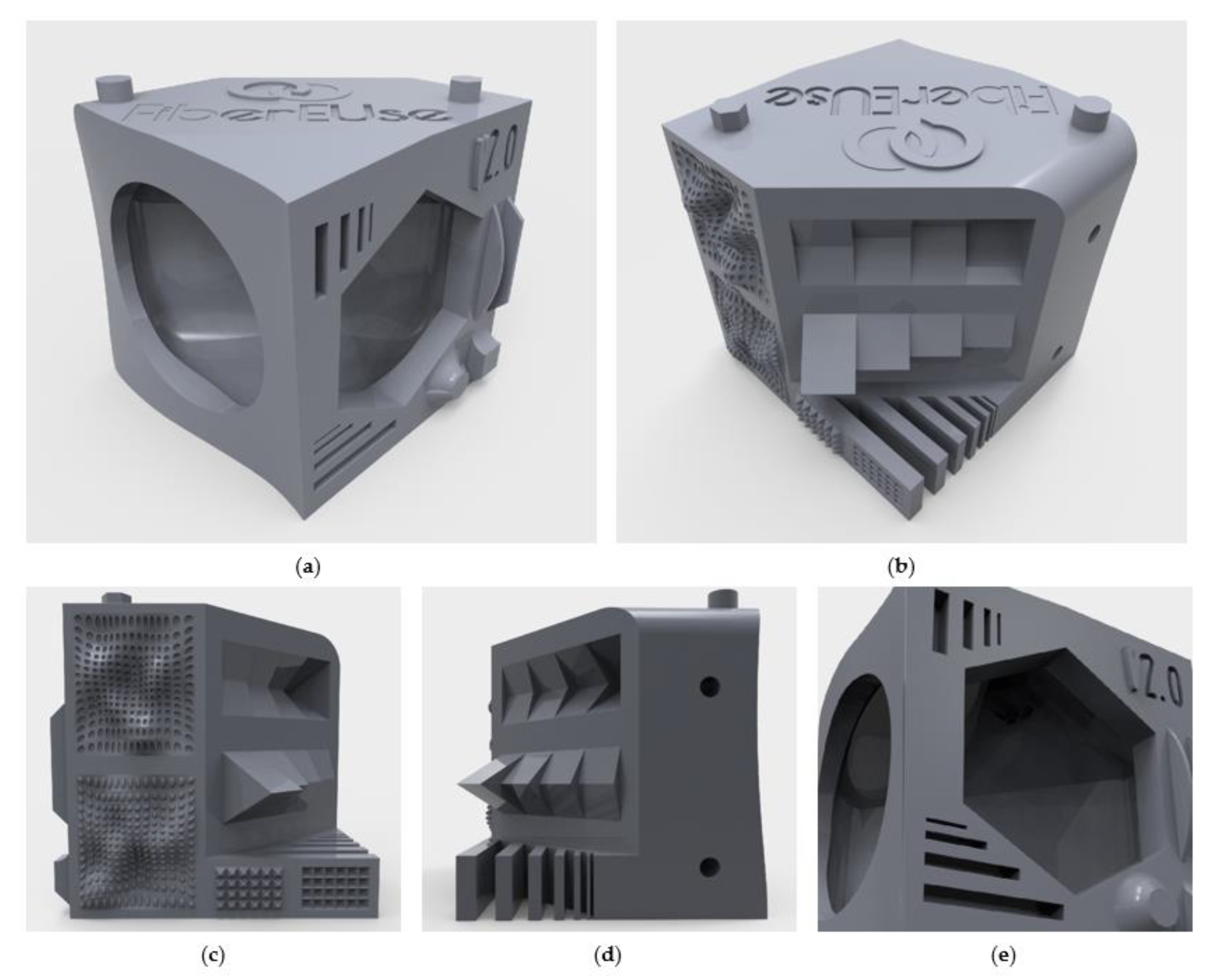
The overall preview of the finishing torture test sample is shown in
Figure 1a,b. The maximum dimensions of the 3D model (53 × 53 × 53 mm
3) were defined to limit the 3D printing times of a single piece. The shape is comparable to a cubic-like volume, and several technical features are placed onto the different surfaces. Their dimensions and positions vary in order to verify both the homogeneity of the post-processing treatment and the shape accuracy after the metallization at different conditions. The specific features are visible in
Figure 1 and listed here below:
Linear engraving with a maximum depth of 3 mm and a minimum dimension of 0.5 × 5 mm
2 (
Figure 1a,e);
Letter engraving and embossing with a depth from 0.2 to 0.6 mm and a height of 0.8 mm (
Figure 1a,e);
Geometrical embossing with a height from 0.2 to 0.6 mm (
Figure 1a,b);
Staircase effect and overhangs with an angle from 30° to 75° (
Figure 1b,d);
Spacing features with a distance from 0.5 to 3 mm (
Figure 1b,d);
Surface embossing and engraving with a maximum surface variation of 4.5 mm and a nominal depth or height of 0.5 mm (
Figure 1b,c);
Internal cavity with a maximum overhang of 40° (
Figure 1a,e);
PVD sputtering fixing holes dimensioned according to the PVD sputtering equipment of the industrial site (
Figure 1d).
Considering the main purpose, this finishing torture test sample could be suitable for evaluating the surface finishing quality of different post-treatment processes for FFF 3D-printed parts, such as chemical or physical surface treatments [
31,
32] and other thermal spray technologies. By changing some features, it may be also used to test the surface finishing of 3D-printed surfaces obtained from nonplanar slicing for FFF processes. This novel approach allows the reduction of the staircase effect and the layer-by-layer appearance in nonplanar toolpaths during the fabrication of a 3D-printed part [
33,
34,
35]. Finally, a similar finishing torture test sample can be designed for other material extrusion 3D-printing technologies as well as new emerging materials.
3.3. The 3D Printing and Metallization of the Finishing Torture Test Samples
Five finishing torture test samples were successfully 3D printed with the parameters and materials previously shown in
Table 1, i.e., PLA, ASA, PC-ABS, HT-PE, and XT-PE-CF20. In general, delamination of the layers occurred only for the tests made with ASA and PC-ABS. The most affected areas correspond to the vertical sharp edges and near the internal cavity. Moreover, ASA had also some adhesion problems during the 3D printing, and a raft base was added to the Gcode to improve adhesion to the building plate. No significant superficial defects were detected on the surfaces of the 3D-printed tests, except on the overhang surfaces of the finishing torture test samples made with XT-PE-CF20. At the same time, the surface finishing of this composite material slightly hindered the layer-by-layer appearance of the piece in the
z-axis direction, and a random texture can be noticed in the same direction. These aspects are generally noticed in the case of reinforced filaments for two main reasons. Since the presence of fillers highly reduces the printability of these kinds of filaments, a nozzle with a larger diameter is required to avoid clogging inside the hotend, reducing the overall definition of the piece. Moreover, the presence of the filler contributes to modify the surface texture. As a matter of fact, the composite material slightly hinders the layer-by-layer appearance of the piece, thanks to the texture created by the reinforcement particles. Contrastingly, thermoplastic filaments highlight the layer-by-layer appearance. Especially for the ASA filament, the layers are clearly noticeable on the whole finishing torture test sample.
After the PVD sputtering metallization, some considerations can be made by comparing the overall quality of the chromium layer. The quality of the coating is generally higher on planar surfaces without embossed or engraved details. Although the five specimens were successfully coated, several differences can be noticed, according to the different material of the substrate as explained in detail in the following:
The PLA sample does not show detachments of the chromium layer, and there are no surface defects due to the metallization. Despite the low Tg, any geometrical deformation is not visible, and good homogeneity was achieved.
The delamination of the ASA sample worsened after the metallization. New delaminated points have appeared, and the old ones are enlarged in their dimensions. Moreover, some bubbles can be noticed on the lower surface of the test. These may be due to some entrapped air between the layers, due to the 3D printing and/or PVD sputtering settings. Nevertheless, no detachments and geometrical deformations were detected.
For the PC-ABS sample, the delamination has worsened after the PVD sputtering process. The behavior is similar to the ASA sample.
The HT-PE sample does not show detachments or superficial defects linked to the metallization or geometrical deformations. A good homogeneity was achieved also in this case.
The XT-PE-CF20 sample shows a less shiny surface and lower homogeneity of the chromium layer when compared to the other samples, probably due to the filler. However, no detachment or geometrical deformation was found after the metallization.
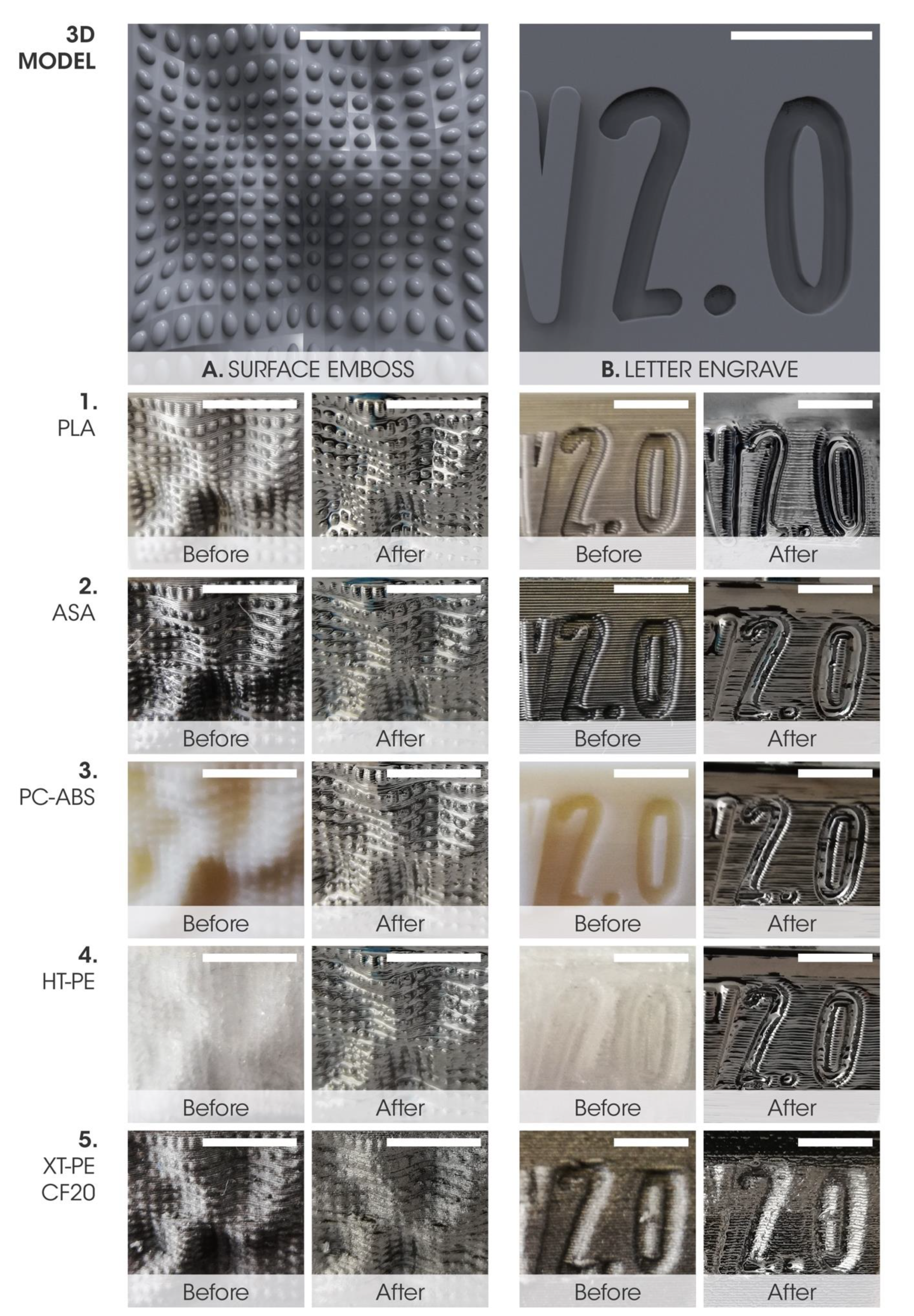
In particular, two surface details (surface embossing and letter engraving) and two 3D-printing features (internal cavity and staircase effect) were evaluated through a comparative analysis of the samples. A picture before and after the PVD sputtering metallization was taken for each finishing torture test sample to allow two levels of comparison: (i) the overall quality before and after the coating process; and (ii) the metallization onto the same geometry made with different materials. The comparison of the surface embossing and letter engraving is resumed in the visual matrix of
Figure 2. In general, the embossing details were quite visible after the metallization, except for the XT-PE-CF20 test (
Figure 2, detail A5). Among the samples under consideration, the highest homogeneity was observed for the PLA sample (
Figure 2, detail A1). Contrastingly, the definition of the engraved details worsened in most of the cases. Some inhomogeneity of the chromium layer can be detected in the ASA and PC-ABS samples (
Figure 2, details B2 and B3). Furthermore, the layer-by-layer appearance of the PC-ABS and HT-PE tests was highlighted by the metallization (
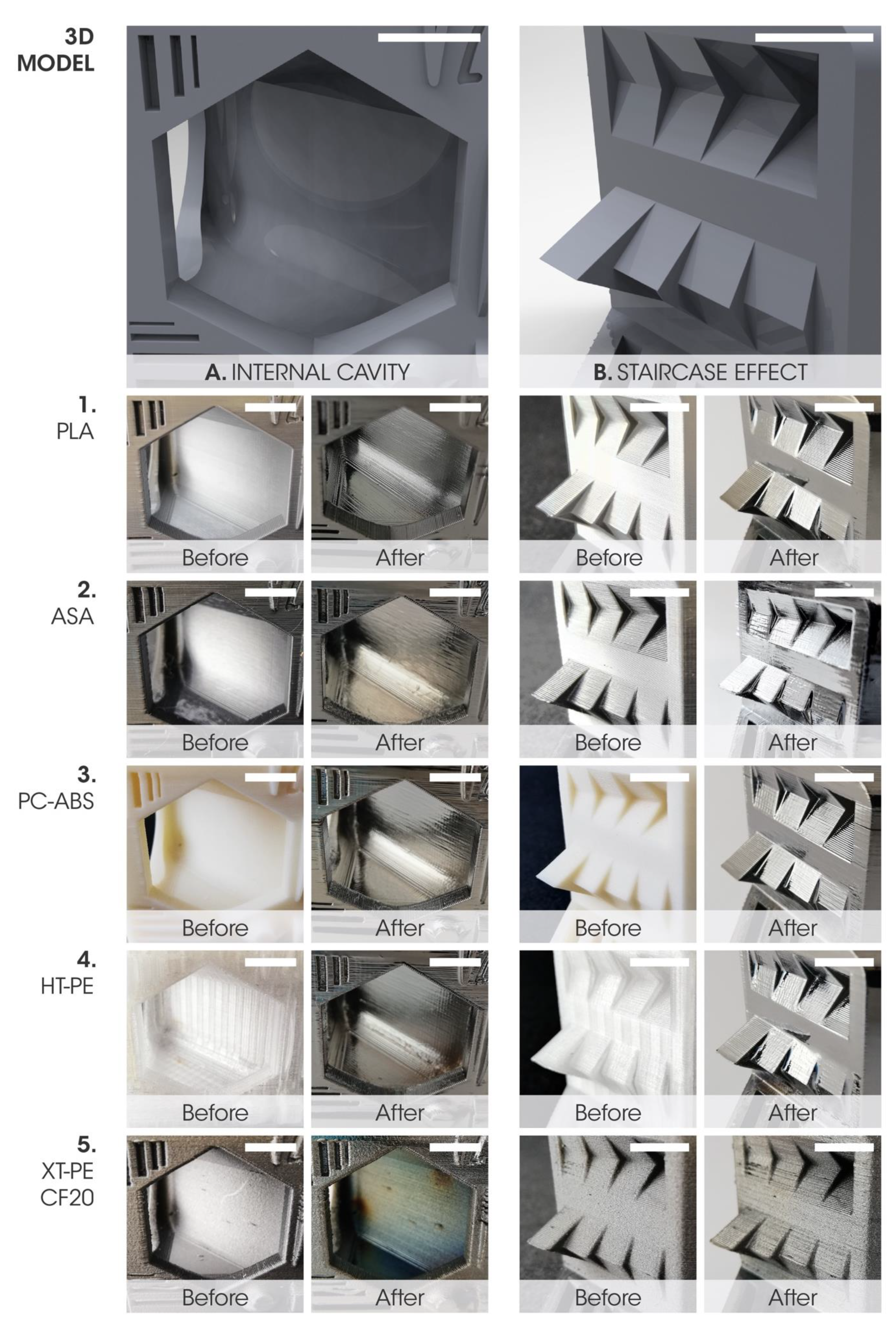
Figure 2, details B3 and B4). In principle, this may be related to the inhomogeneity of the primer layer close to the finest surface details. Further remarks can be made, according to the visual matrix shown in
Figure 3. The internal cavity was successfully coated for all the five samples, although the chromium layer of the XT-PE-CF20 test was not homogeneous (
Figure 3, Detail A5). Detachments near the cavity are visible in the PC-ABS test (
Figure 3, Detail A3). This is also visible beside the detail to evaluate the staircase effect (
Figure 3, Detail B3). Some superficial defects were present in this specific area after the metallization of the XT-PE-CF20 sample (
Figure 3, Detail B5). From the figures, the staircase effect seems to be highlighted by the metallization, except for the ASA sample (
Figure 3, Detail B2).
However, geometrical deformations of the engraved and embossed details were not visible. This result is in agreement with the Tg of the materials previously shown and the temperature range of the PVD sputtering process (20–60 °C). Even for the PLA samples, residual thermal stresses did not significantly affect the final results.
To quantify the quality of the metallized surfaces, the roughness of the sample surfaces was measured before and after the PVD chromium sputtering process. In detail, vertical surfaces were selected, as they better show the typical roughness of the 3D-printing process, hence metallization can show more improvements in those specific areas. As visible in
Table 4, the roughness values after the metallization are similar in most cases. The best results were obtained by the HT-PE sample, which also exhibited higher reduction in roughness in terms of root mean square. The XT-PE-CF20 sample showed the highest roughness both before and after the metallization process. In particular, this can be due both to the poorer initial quality related to the use of a larger nozzle (0.6 mm) to avoid fiber-clogging issues, and the presence of carbon fibers, which could be exposed on the surfaces, creating a non-homogeneous substrate for primer and, consequently, for PVD sputtering.
3.4. Fields of Application
New applications can be found for 3D-printed thermoplastic and composite materials coated with a metallic layer, although further quantitative tests should be performed to better analyze the PVD sputtering metallization of the selected substrates. As previously mentioned, these kinds of surface coatings were already used for medical and electronic applications with other additive manufacturing processes, i.e., stereolithography [
36]. Furthermore, PVD sputtering represents a feasible way to deposit metallic films on FFF 3D-printed substrates, achieving new surface properties [
13]. As a result, other technical applications can be exploited after the optimization of the PVD sputtering process, such as in the automotive and furniture fields. New customized and high-performing parts can be fabricated for the automotive industries by taking advantage of both the 3D printing of polymer-based materials and metallization. As a matter of fact, FFF offers a larger range of 3D printable thermoplastics and composite materials when compared to stereolithography as well as the possibility of printing bigger volumes. PVD sputtering could be also used to enhance and change the senso-aesthetic qualities of a specific 3D-printed surface since surface finishing strongly influences not only the performance of a specific product, but also its perception and the emotional response of customers and final users [
37]. For instance, designers can highlight or hinder the layer-by-layer appearance of the final product to stimulate a specific response through a proper selection of the substrate material and of the surface finishing. For this reason, customized 3D-printed furniture can benefit from several advantages of metallization not only from a functional perspective, but also from an aesthetic and emotional point of view, i.e., extending the life cycle, protecting the external surfaces, improving the abrasion resistance, and changing the user perception of a 3D-printed product through its finishing. However, aging effects could occur on the chromium/polymer-interfaces, for example, due to redox reactions, occurring at metal/polymer interfaces and chemical reactions caused by the interactions of chromium with carbonyl groups and aromatic rings [
38]. For these reasons, future studies will also be dedicated to the investigation of these phenomena. Moreover, PVD sputtering process can be considered an environmentally friendly surface treatment since dangerous chemicals are not used for metal deposition [
13].
3.5. Cost Analysis
Finally, to estimate the impact and the cost-efficiency of the proposed metallization process for future industrial exploitations, a cost analysis was performed. More specifically, the costs for the surface treatment and PVD sputtering of torture test samples were determined, including the costs for the coating raw materials, electricity, common gases (such as nitrogen and argon), and periodic maintenance (
Table 5).
Considering the results obtained by this cost analysis, it is possible to state that the costs related to energy consumption are approximately 4% of the total cost and have the least impact on the final price. Vice versa, the costs related to the raw material and the operator labor have a greater impact on the total cost (i.e., 20% and 22% of the total cost, respectively). The coating raw materials are usually the highest cost consumables. However, the final cost of the entire metallization process per sample is lower than EUR 1. This means that costs can be measured in cents, for example, for decorative PVD applications on consumer products. Therefore, this PVD sputtering metallization will not add substantial costs to a manufactured part; adding PVD finishing to manufacturing operation can be cost-effective. Moreover, the deposition of a chromium layer enhances the perceived quality of products, because a high-quality product finishing instantly communicates its increased value and influences how customers view manufactured products [
39]. For instance, automotive components can be customized by an FFF printing process and then exhibit different senso-aesthetic qualities, thanks to the PVD sputtering metallization. This suggests that, even though the initial investment of a PVD sputtering equipment may be high, it allows the 3D-printed objects to combine customization with good, appealing properties. With that said, in this specific case, the capital expenditure, which represents the cost of buying, maintaining and improving the equipment, is only the 10% of the final cost for the metallic coating of a single object. Furthermore, durable hard coatings can enhance the lifetime of home and office furniture, medical devices, industrial tooling, sporting goods, and many other products, which require being custom-made by 3D printing for fashionable and particular reasons.
4. Conclusions
In this work, the deposition of a chromium layer onto 3D-printed complex shapes was successfully achieved. Five thermoplastic and composite materials were coated through a PVD sputtering process. In detail, the glass transition temperatures and mechanical properties of the selected materials were evaluated not only to preliminary define their PVD processability, but also to showcase the metallization of 3D printable materials with different characteristics. Considering the maximum temperatures reached during PVD, only PLA parts should have been affected by deformations linked to residual thermal stresses. Nevertheless, no visible deformations were found on the PLA torture test sample after the metallization.
A finishing torture test sample was specifically designed to test metallization onto different features that are commonly fabricated through FFF processes. Additionally, this 3D model may be useful to evaluate (i) the quality of different surface finishing for 3D printing; (ii) different 3D-printable materials for FFF; and (iii) other material extrusion 3D-printing processes and slicing approaches after some changes to the main features. Afterward, the 3D printing and metallization of the torture tests were successfully achieved with all the selected materials. In general, good homogeneity was obtained with PLA and HT-PE, whereas the metallization onto the other materials was mainly affected by the presence of 3D-printing defects. Among the materials under investigation, the HT-PE sample exhibited the lowest values of roughness after the PVD sputtering process and the highest reduction of roughness induced by the metallization. Moreover, neither detachments nor geometrical deformations and surface defects due to the metallization process were observed for HT-PE. Especially for applications requiring high thermal stability and good mechanical properties, HT-PE samples can be an appropriate choice, due to the high values of the glass transition temperature and good quality of the PVD sputtered surfaces. However, any detachment of the chromium layer or geometrical deformation was not observed for the carbon-based composite (XT-PE-CF20), and promising results were also achieved in this case.
Considering the different properties of the materials shown in this work, a wider range of new applications can be developed, i.e., in the automotive and furniture sectors. As a matter of fact, this finishing treatment can influence not only the technical properties of new products, but also the user perception. Further quantitative tests should be performed to foster the use of PVD for 3D-printed thermoplastics and composites, such as assessing the abrasion and adhesion resistance of the coatings. Nevertheless, these promising results will potentially allow the exploitation of 3D-printed thermoplastics and composites for the design of new products.


 ,
, 


