1. Introduction
Chaotic systems are nonlinear systems with many complex characteristics. Due to the randomness of chaotic systems, they can be applied in many aspects, especially in secure communication. For application in secure communication, chaos synchronization is the most important issue, and some control methods for chaos synchronization have been developed in the literature. In the report [
1], the adaptive fuzzy control approach is designed to deal with the synchronization for time-delay uncertainty chaotic systems. In [
2], the sliding mode control is utilized in the process of synchronization for the chaotic system with disturbances. It is well known that the sliding mode control (SMC) is a nonlinear control method using a discontinuous control signal to force state trajectories to hit the switching surface and enter the sliding manifold such that the Lyapunov stability for the controlled systems can be ensured. Moreover, SMC is an effective method to eliminate the influence of the matched disturbances [
3,
4,
5], and the design of SMC often combines with the disturbance estimator or observer to achieve better robustness [
6,
7,
8]. Due to this reason, SMC has been widely used to solve the robust control problems for many problems in engineering. However, there is a chattering phenomenon due to the utilization of sign function in SMC, which causes the high-frequency oscillation in the controller. To solve this problem, there are some alternatives, such as high-order SMC [
9,
10], second-order SMC [
11,
12], and saturation function [
13]. Thus, in this paper, we also introduce the saturation function to avoid the chattering phenomenon and achieve the chaos synchronization.
To develop the digital-redesign SMC, we introduce the digital redesign approach to transform a well-designed continuous-time SMC to a corresponding discrete-time SMC directly and keep the control performance. There have been many control laws designed with the digital-redesign method, for example, the
and
continuous-time controllers are redesigned to the discrete-time controllers by the digital-redesign method [
14]. In [
15], the authors also presented a new digital-redesign control scheme applied to a high-gain analogy controller and improve the state responses. Thus, one can know that the digital redesign method is an effective approach to discretize the continuous-time controller and maintain the performance of the designed continuous controller as possible.
Chaotic synchronization methods are often used in secure communications by embedding the private information in the state equations of the transmitter and synchronizing the states on both sides to achieve the secure communication [
16]. However, secure communication with the chaotic system may be destroyed by noise and external disturbances [
17], in other words, the response of the chaotic system is sensitive to the initial conditions; therefore, the proposed digital-redesign SMC-based controller utilizes this property to reconstruct the transmission message for achieving secure communication. In [
18], the sliding mode observer is designed for the secure communication and recovery of the desired message from the chaos trajectory. In [
19], an adaptive terminal sliding mode tracking scheme is proposed for synchronizing the chaotic systems. Therefore, we combine the chaos secure communication with the SMC to the image encryption algorithm, and the designed secure key as a message is embedded in the state equation of the transmitter and securely sent to the receiver through the synchronization to perform the decryption in the receiver part. Due to the properties of the pseudo-randomness sensitivity to initial condition and unpredictability in the chaotic systems, the image encryption algorithm can be strengthened. Furthermore, the S-box is established to have secure encryption. The S-box is a core component to provide higher security properties and is widely used in image encryption. There have been many approaches proposed for image encryption based on chaotic systems [
20,
21,
22,
23]. In [
20], an image encryption scheme based on the pseudo-orbits of 1D chaotic maps is proposed for image encryption. However, the synchronization problem was not considered. In [
21], Moon et al. introduced the self-synchronization approach for generalized Lorenz chaotic systems and applied it to image encryption. But the proposed synchronization approach was difficult to extend to general types of chaotic systems. In [
22,
23], the authors integrated the randomness of the chaotic signal to construct S-boxes and apply some methods to increase the execution efficiency. However, the mentioned researches above are all used the continuous controller to achieve chaos synchronization. Today, with the advancement and popularization of digital signal processing (DSP) technology, to simplify control circuit realization and reduce design costs, there is a current trend to use digital microcontroller to implement control solutions. However, to utilize the DSP microcontroller to implement the control schemes, the traditional continuous-time control design methods mentioned above for chaos synchronization cannot been applicable. Therefore, we aim to propose a novel discrete digital-redesign SMC which can be easily realized by using the microcontrollers to guarantee the chaos synchronization and then applied to image encryption. To complete the design, the analogy chaotic systems are established and the secret message is embedded in the master chaotic system such that it does not appear on the public channel. Then, the digital redesign sliding mode controller is proposed for synchronizing chaotic behavior. After the chaotic systems are synchronized, the embedded message can be reconstructed at the receiver and adopted for the image encryption.
The structure of this paper is given as follows. In
Section 2, the structure of the secure communication based on synchronization is introduced. In
Section 3, the image encryption algorithm is proposed and the performance index to show the strength of the algorithm is discussed. In
Section 4, the results are concluded.
In this paper, denotes the transport for a matrix . represents the Euclidean norm of a vector . denotes the identity matrix. is the absolute value of a constant . denotes to the pseudo inverse matrix for a matrix and . is the nonlinear sign function of and if , ; if , ; and if . .
2. Communication Structure Based on Synchronization
A. The secure communication based on chaos synchronization.
In this section, a secure communication based on synchronization is formulated. Due to the characteristic of chaos synchronization, the message can be embedded in the master system and obtained in the slave system through the SMC synchronization control method.
First, the structure of the master system can be described as
and the slave system is described as
where
and
are the system matrices,
and
are the nonlinear terms of chaotic systems, and
is the embedded message.
The error vector is defined as
and the error dynamics can be obtained as follows:
where
. When the synchronization is ensured, it means the error state converges to zero, i.e.,
, and
will converge to zero as well. Then, the equivalent error dynamics can be rewritten as
is the system matrix and not be equal to zero, therefore, one can derive that . As a result, the message can be recovered in the slave system if the synchronization is ensured.
B. SMC design for message communication.
First, to achieve the sliding mode control for completing chaos synchronization, the sliding mode function can be selected as
where
, and
is the designed controller gain. By differentiating (5), we have
When the controlled state trajectories enter the sliding manifold, the equivalent controller with the fact of
can be derived as
Thus, one can know that the equivalent controller is equal to when the error converges to zero which is mentioned in (4).
To guarantee the minimization of the state error
, we use the linear-quadratic method [
24] to calculate the controller gain
which will be used in the sliding mode function (5). We consider the cost function as follows
where
,
is a positive define matrix. According to the above performance, we have the Riccati equation as
where
is a positive symmetric define matrix. Thus, one can obtain the gain
:
To ensure the controlled dynamics, (3) can enter the sliding manifold, the controller is designed as follows:
Replacing (11) into (6), (6) becomes
where
and
are positive parameters and
is chosen as
, where
. To verify the designed controller can ensure the occurrence of the sliding mode, a Lyapunov function is chosen as follows:
and then one differentiates (13) and obtains
From (14), one can know that when is chosen as . Thus, the design of SMC (12) is complete through the above derivation.
There is a chattering phenomenon when the design of SMC includes the nonlinear
function. To overcome this situation, we replace
function with saturation function
[
13]. The saturation function is shown as follows:
where the parameter
is an arbitrarily small but positive constant. Therefore, one can obtain the continuous-time SMC-based control law for secure communication as follows:
While the sliding mode is reaching, the synchronized error approaches to zero, the desired message can be established by the control law (16) in the continuous time.
C. Digital redesign of SMC for message communication
After obtaining the continuous-time SMC-based controller, we utilize the digital-redesign method to make the transformation and obtain the corresponding discrete-time SMC controller. First, one can discretize (9) with Euler’s method [
25] and get
where
is the sampling time. To guarantee the occurrence of the sliding manifold in the discrete-time domain, Lemma 1 is given as follows.
Lemma 1 The following reaching condition is considered. [
26].
where
. If the reaching conditions above are satisfied, then the controlled state trajectories can converge to
and enter the sliding manifold.
Proof of Lemma1: when , means and the trajectory of converges towards the sliding surface . When , means and the trajectory of also converges towards the sliding surface . Therefore, if the reaching conditions above are satisfied, the controlled state trajectories can converge to and enter the sliding manifold.
Based on Lemma 1, we calculate
Therefore, according to Lemma 1, will always converge to zero and the controlled system enters the sliding manifold. In this paper, Euler’s method is adopted to discretize the proposed sliding mode controller such that the existence of the sliding mode can be guaranteed and the equivalent control can be achieved.
When the system is in the sliding manifold, i.e.,
as given in (7), the error dynamics can be discretized as
where
, and
. Due to zero-order-hold (Z.O.H.), the controller
can be approached to
, for
, and
can be approximated as
According to (20), (21) can be rearranged as
where
. Since the reaching condition is satisfied, the controlled system is operated in the sliding manifold. The digital-redesign method is utilized to ensure that
is Hurwitz and the stability of the controlled system can be guaranteed. Furthermore, to achieve the digital-redesign-based SMC, one can discretize (8) to implement the discrete-time SMC as follows
Finally, with the utilization of the proposed digital-redesign method and the adoption of the saturation function (15), the discrete SMC synchronization scheme can be obtained as
While the sliding mode is reaching, the synchronized error approaches to zero, the desired message can be established by the control law (16) in the discrete time.
D. Simulation for message communication
After completing the design of the digital redesign SMC synchronization controller, the simulation for verifying the feasibility is performed with the Lorenz chaotic system which can be found in reference [
27]. The Lorenz chaotic system is given as follows:
where,
,
and
.
First, one rearranges the Lorenz chaotic system as the structure of the master-slave system considered in (1) and (2) for secure communication as follows
and
where the system matrices are
,
,
, and
. Then, the message
is given with
, and embedded in the master system. The parameter in the controller is chosen with
and
, and the parameter in saturation function is selected as
. The weighting matrices of the cost function are chosen as
and
. The controller gain is calculated as
After using the proposed digital redesign approach, one can obtain
,
,
as below:
and
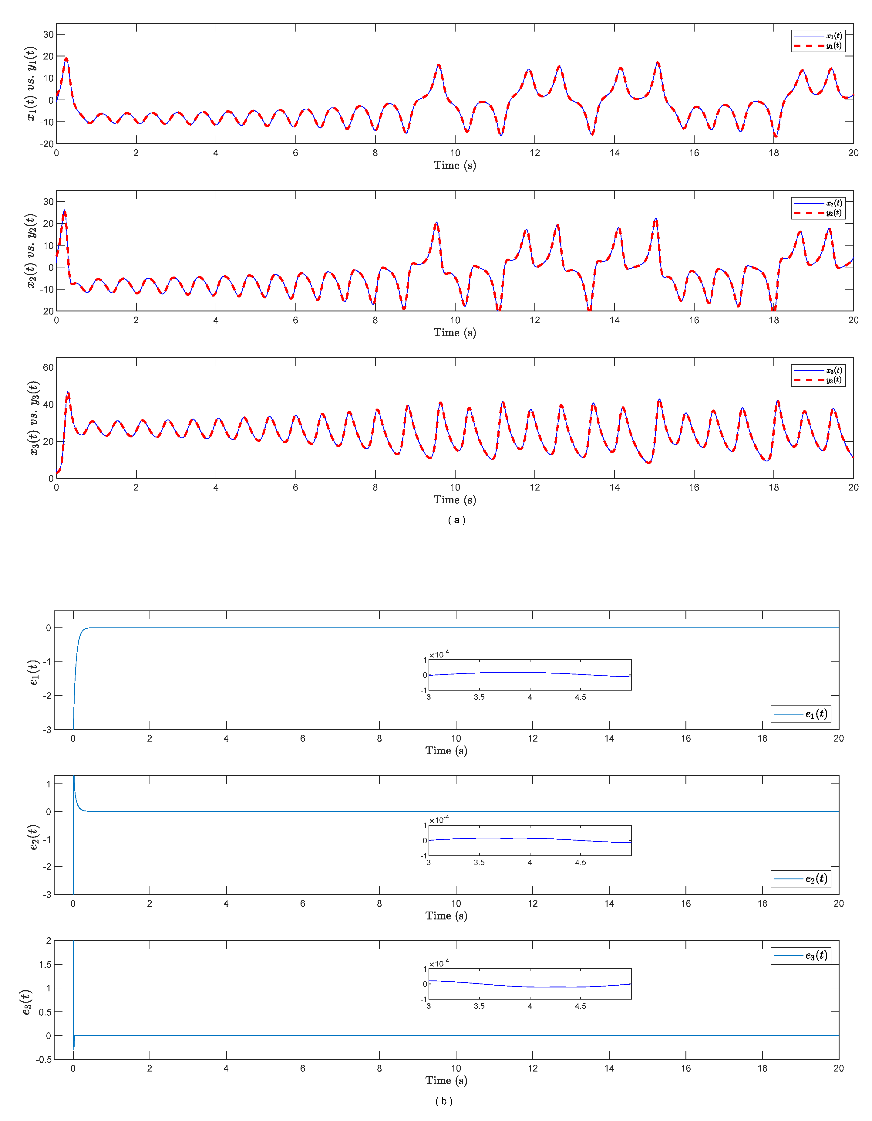
We select the initial conditions as and for simulation. Simulation results are shown as follows.
In
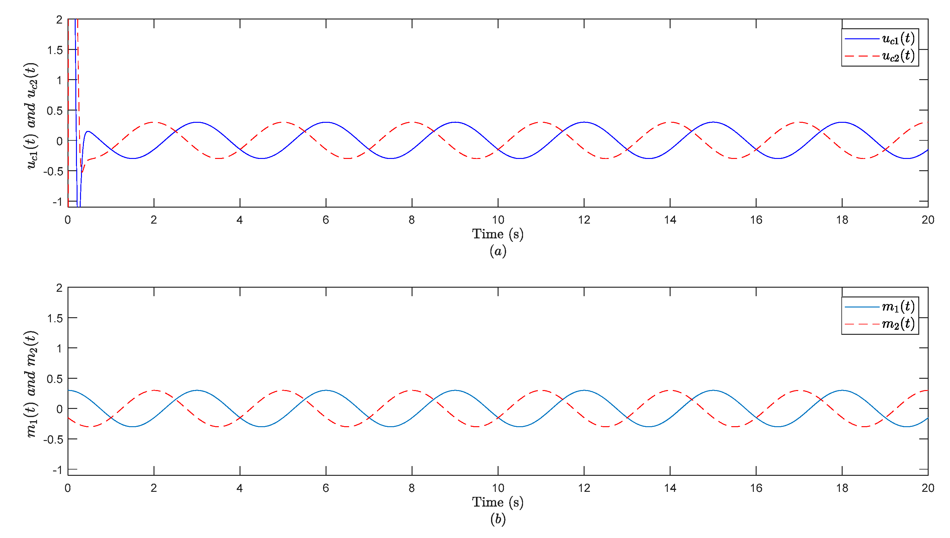
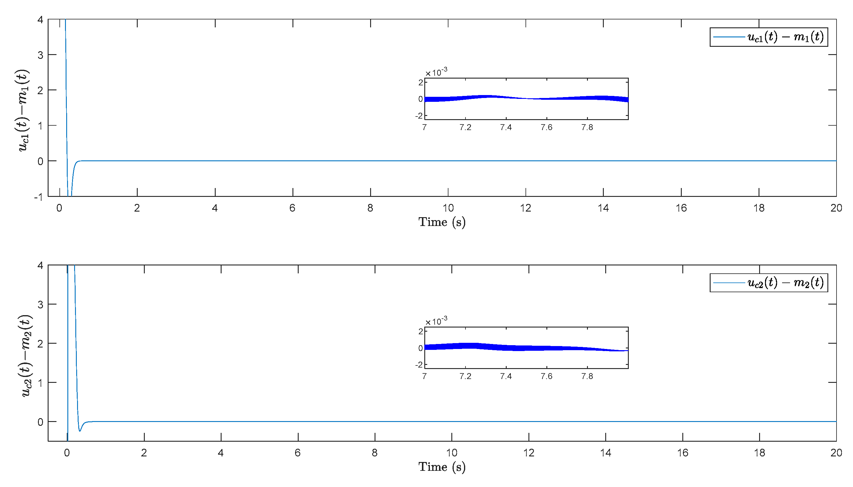
Figure 1, one can observe that the synchronization errors are soon approaching zero, which means the designed controller can make the system achieve synchronization effectively. The errors between controller
and message
converge to zero as shown in
Figure 2 and
Figure 3, which is in accordance with the derivation in (4).
Figure 4 illustrates the sliding mode trajectory also converges to zero as expected. Thus, one can figure out that the digital-redesign SMC-based controller is an effective method to make the system achieve synchronization and establish a secure communication. In
Figure 5, one can observe that the synchronization errors are not stable before 10 seconds, however, the synchronization errors are closing to zero while the control input is active after 10 seconds. Therefore, the proposed SMC controller is effectiveness and robust.
3. Results
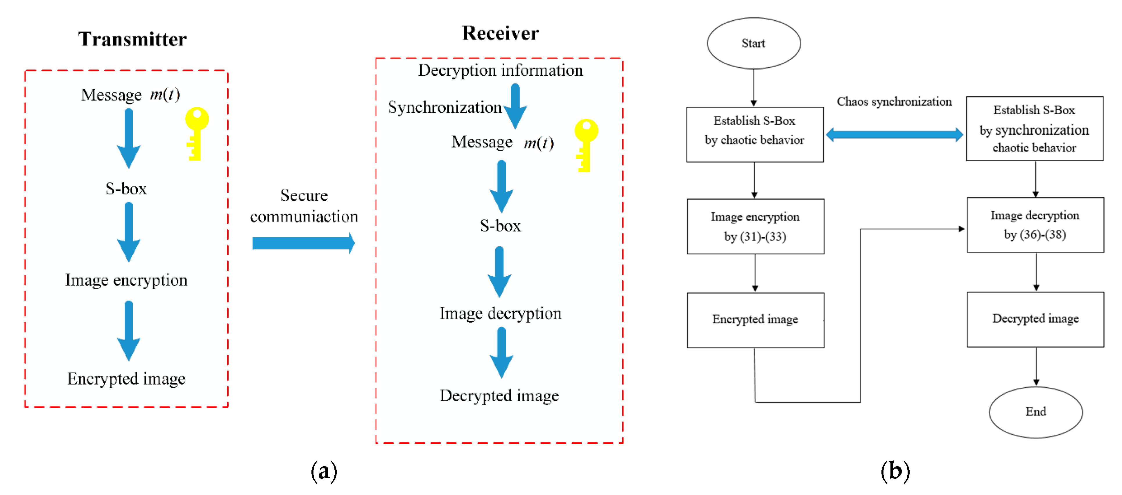
Image encryption based on secure communication
After completing the construction of secure communication with the hybrid synchronization control, the proposed controller is applied in image encryption in this section. First, the secret key for the image encryption algorithm is designed as the embedded message
m(t) and the S-box is established by the secret key. The main function of the S-box is to increase encryption strength. With the secret key and S-box, the image encryption algorithm is proposed. The structure of the synchronization-based image encryption algorithm and flowchart are shown in
Figure 6.
A. Preliminary: establish S-Box by utilizing chaotic behavior
In this section, the secret key and the generation steps of the S-box are introduced. The reconstructed message
is used for establishing the S-box and it is designed as
where
,
, and
are appropriate positive integers,
is an entire time of synchronization simulation, and
is the steady-state trajectory of
. Then, one uses three constants in the message to establish the sample period
for dealing with the state of the Lorenz chaotic system.
where
,
, and
are sampling times and
is a function that rounds the element
to the nearest integer. The constants
,
, and
are the important elements in image encryption and decryption.
After getting the
,
, and
, one can sample the states of the Lorenz chaotic system with
,
, and
respectively, and obtain sampled states
. Furthermore, the simple rules are applied in sampled states to get three sequences,
,
, and
. The rules are shown as follows
where
, the size of the image is
,
for row and
for column, and
is the function to get the mean value of the sequence
and it is a rule. The function of the sampled states is to permute the sequence and obtain the S-box.
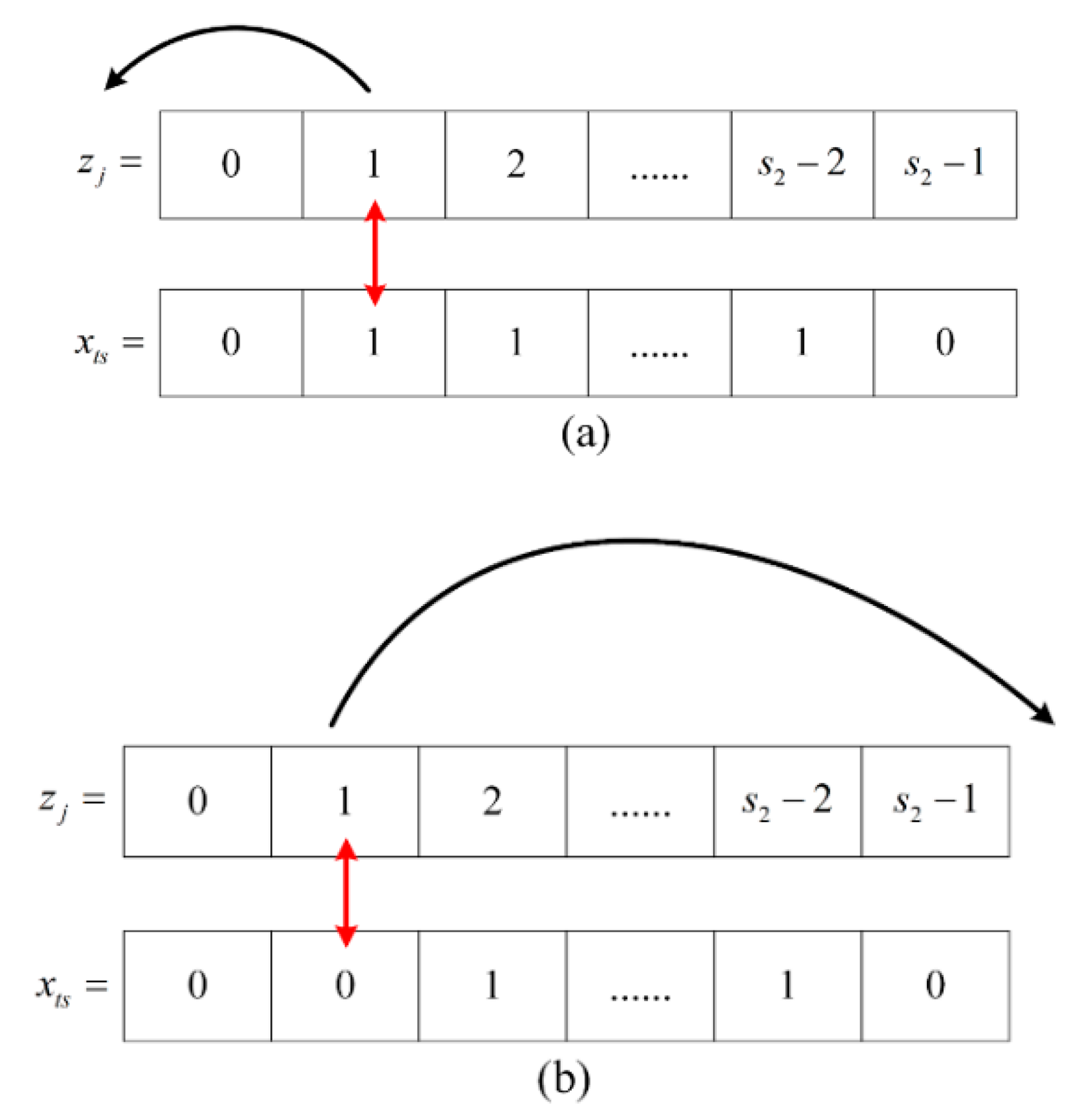
After dealing with the states of the system, one uses it to obtain the S-box_x, S-box_y, and S-box_z. Take the S-box_x, for example. First, one generates a sequence
, and compare the sequence
with the sequence
, where
is the execution times. If the
term of
(i.e.,
) is one, the
term of
(i.e.,
) is arranged to the far left side of the sequence
. If the
term of
(i.e.,
) is zero, the
term of
(i.e.,
) is arranged to the far right side of the sequence
, and replaces the original
after permutation. After completing the permutation from
to
, one gets the new sequence
. Then, one performs the same rules to get
. After running
times, one obtains an
with size
and chooses the last
rows of S-box_1 to build the S-box_x whose dimension is
. Rules for establishing the S-box is given in
Figure 7.
With the rules mentioned above, one can have another two S-box, S-box_2, and S-box_3, which are generated from the and , respectively. Then, one selects the last rows in S-box_2 and S-box_3 to obtain the S-box_y and S-box_z.
B. Image encryption algorithm
After constructing the S-boxes, the image encryption algorithm is proposed with the obtained S-boxes.
Step 1. Separate the image
with the size of
into three grayscale images of red, green, and blue, respectively. Arrange the pixel from row to column, and one can obtain three sequences
where
,
, and
are
th pixel of the red layer, green layer, and blue layer in a color image, respectively.
Step 2. Generate three S-boxes, S-box_x, S-box_y, and S-box_z, with the rules mentioned above and arrange three S-boxes from row to column as
Step 3. Generate three sequences,
,
, and
. Then, one can get
where
denote the bitwise exclusive or operation and
.
With the above three steps, one can obtain three encrypted layers ,, and , and combine three layers to obtain the encrypted color image.
C. Decryption algorithm
In this section, the decryption algorithm is established. The decryption algorithm is just the inverse process of the encryption algorithm. One can obtain some decryption information from the transmitter such as the entire simulation time of synchronization, sampling time , fast sampling time , the state of the master system with the message embedded, and the formula of the sampling time for sampling the state of the system. With the above information, the message is obtained through the approach of synchronization, establishes the same S-box, and performs the following steps to obtain the decryption image.
Step 1. Perform the synchronization to have the message and calculate the sample time for sampling the state with the formula given in part A of
Section 3. Then, sample the state to obtain
.
Step 2. Separate the encryption image
into three grayscale images of red, green, and blue, arrange the pixels from row to column, and get three sequences
,
and
as
Step 3. Establish the S-boxes with the state generated by synchronization and rule in part A of
Section 3 and arrange three sequences as
Step 4. Generate the sequences,
,
, and
, and get the decryption component
,
, and
as follows:
Finally, one can combine three layers, , , and , and obtain the decrypted color image.
D. Simulation results
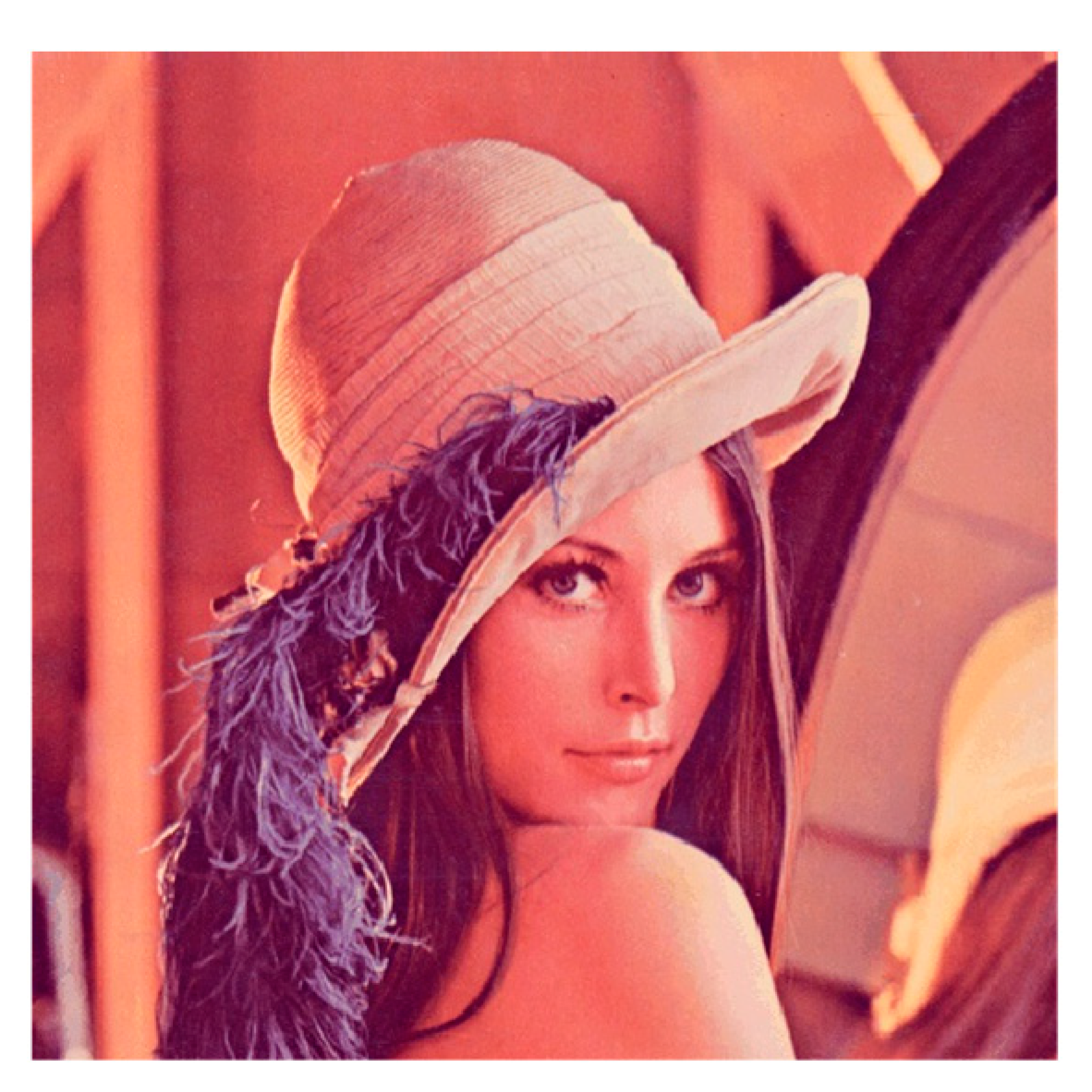
The Lena image with the size
is used as the test image to perform the image encryption. The secret keys are taken as
,
, and
. The plain image of Lena is shown in
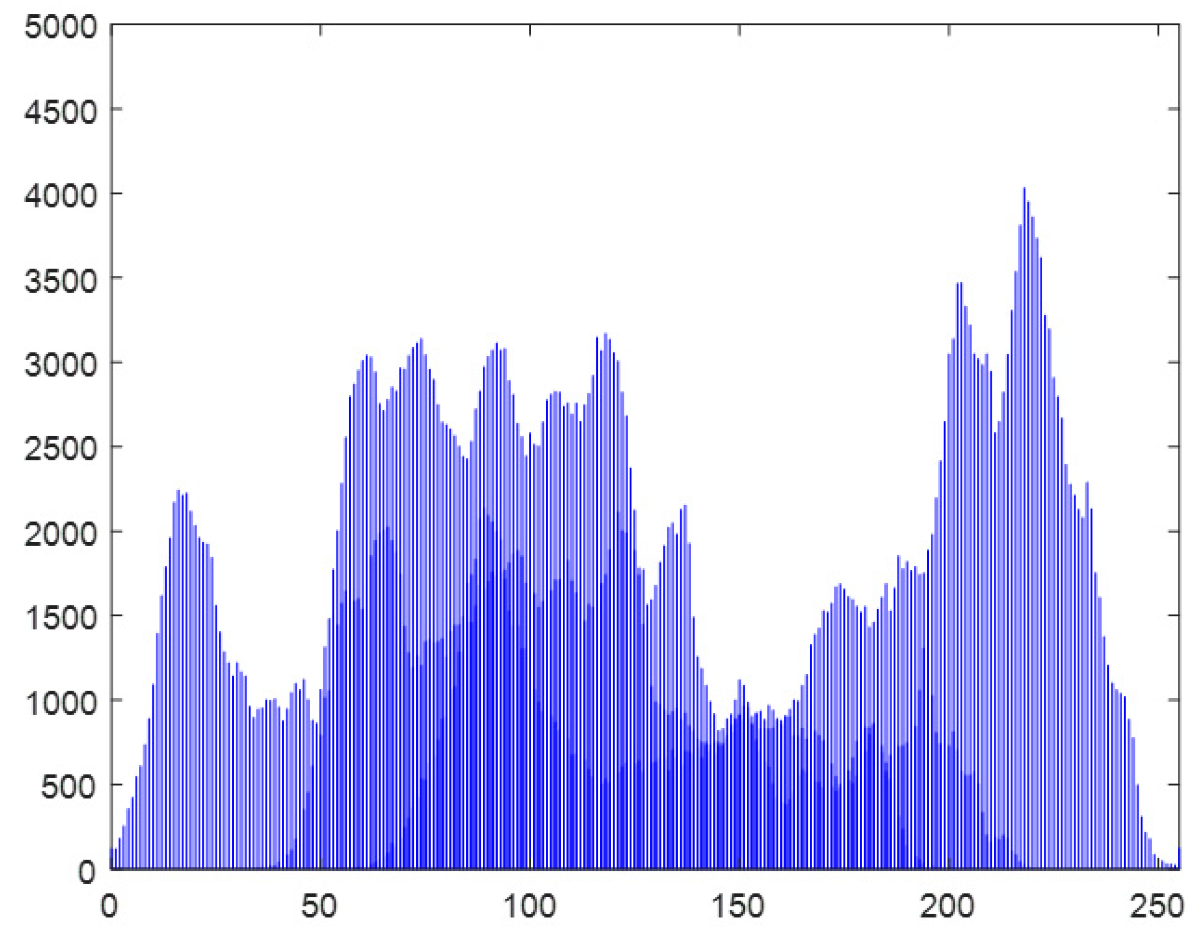
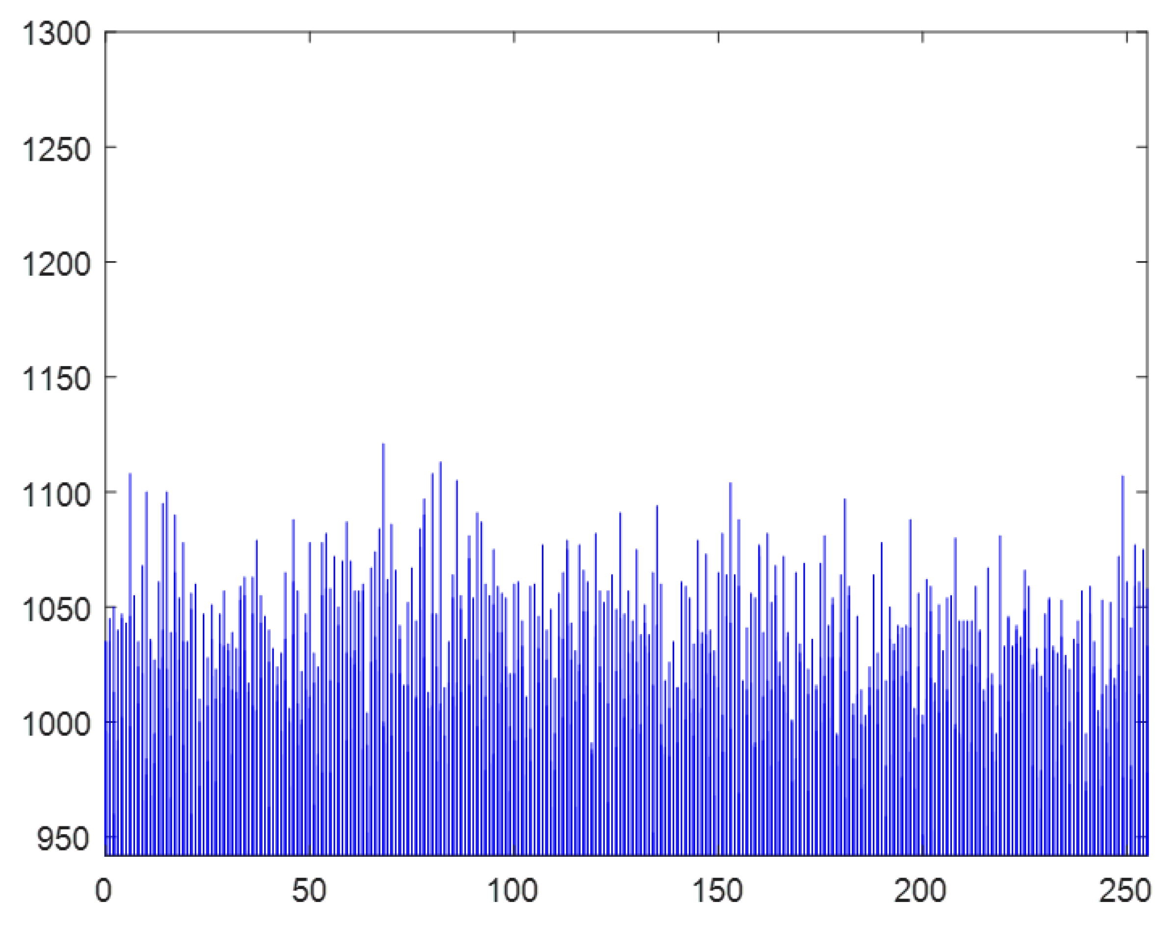
Figure 8 and its histogram is shown in
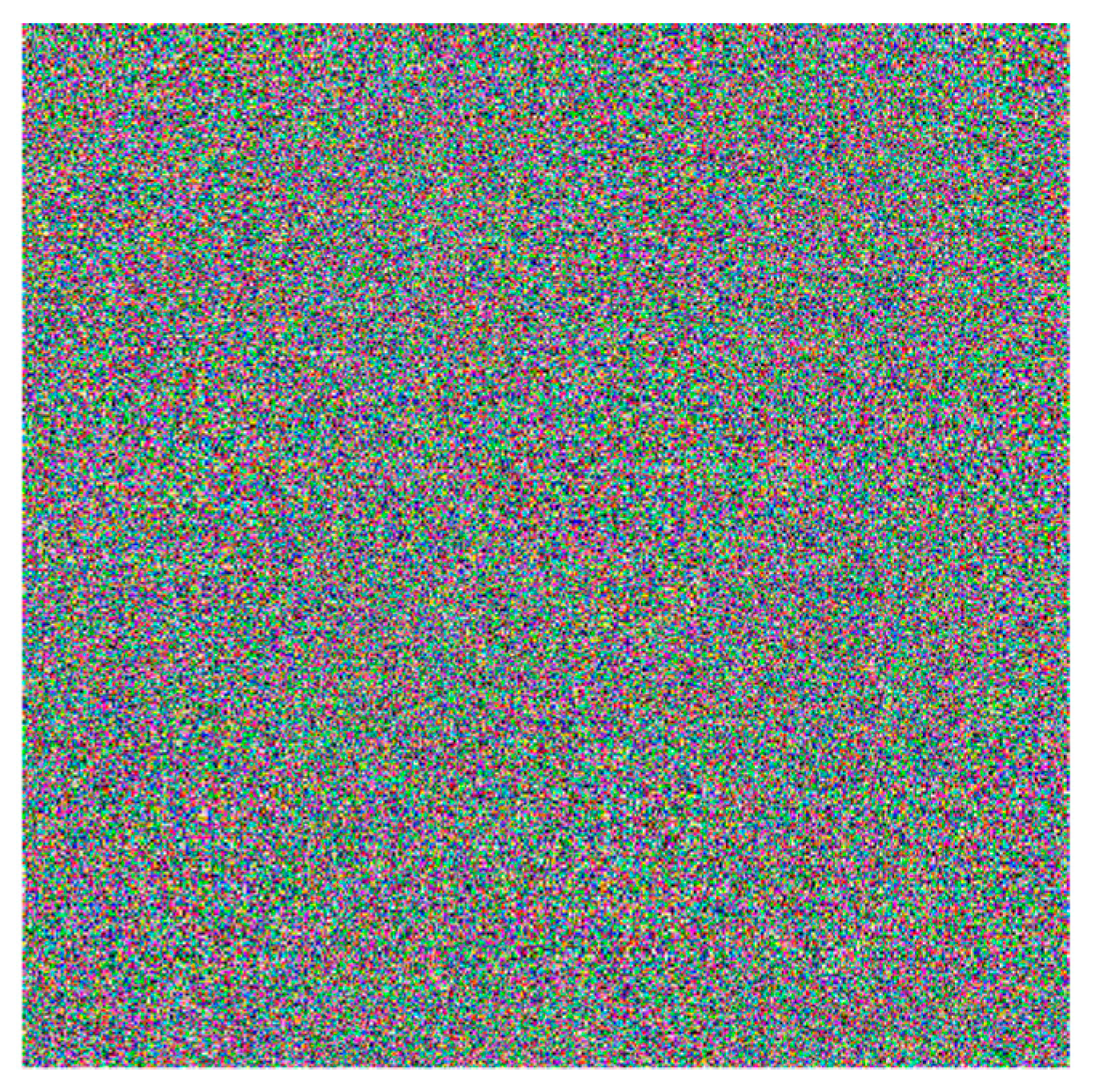
Figure 9. After using the proposed encryption algorithm, one can obtain the encrypted image shown in
Figure 10, and its histogram is shown in
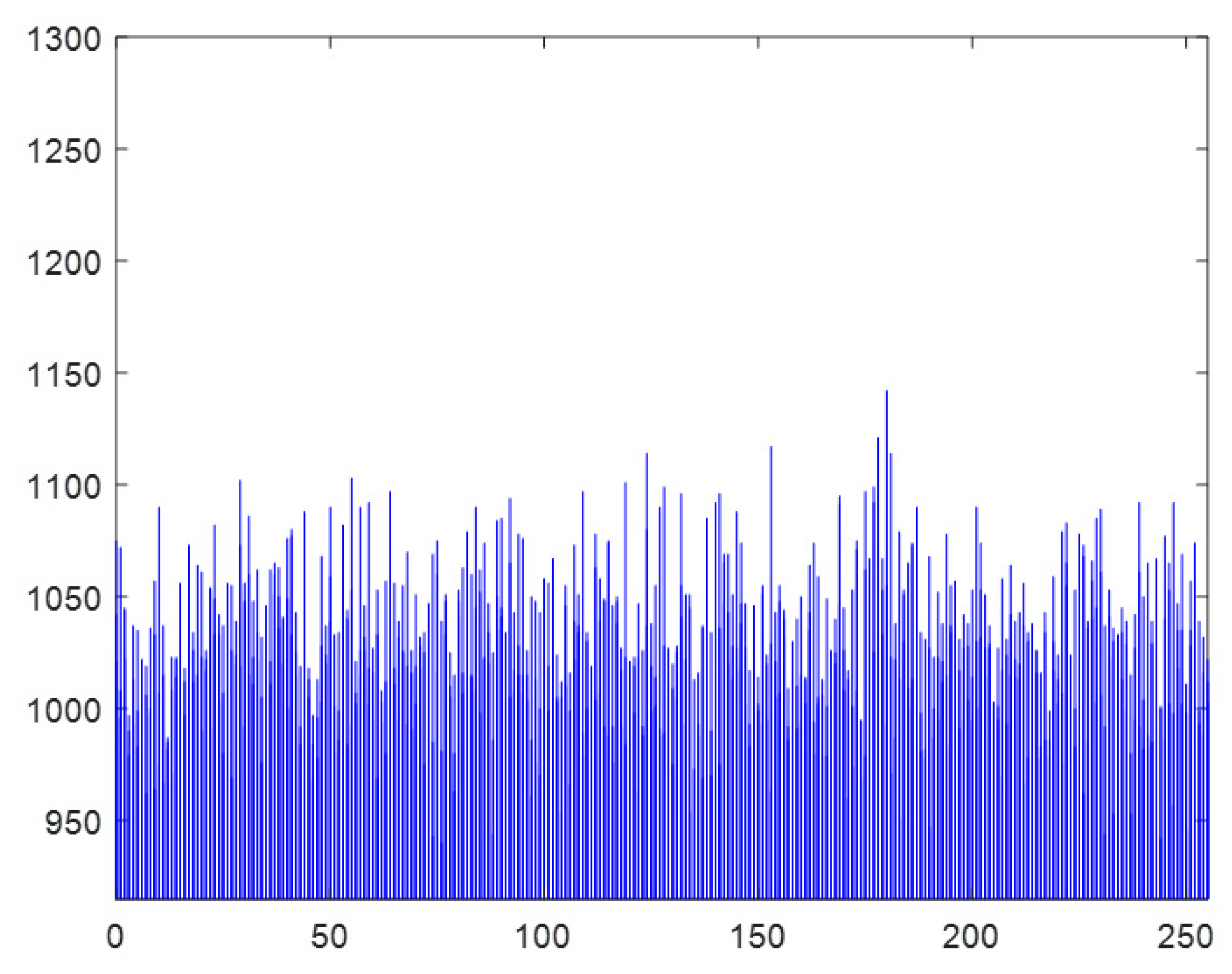
Figure 11. The outline of the Lena is hard to distinguish in the encrypted image. The encrypted image uses all the grayscales from 0 to 255 and the histogram of the encryption image is flat which means the encryption scheme is effective and secure.
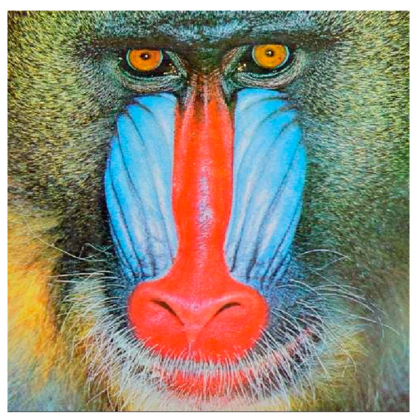
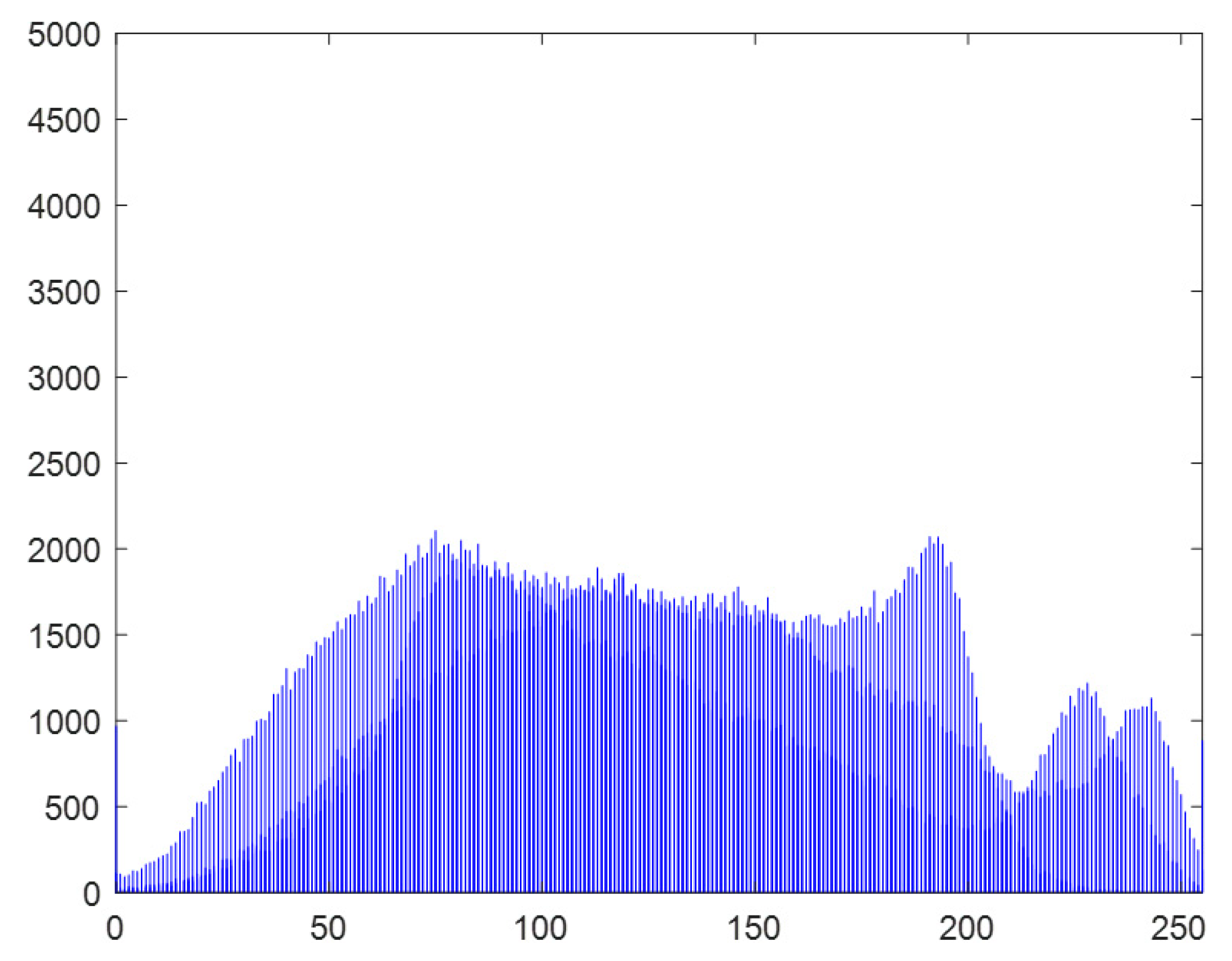
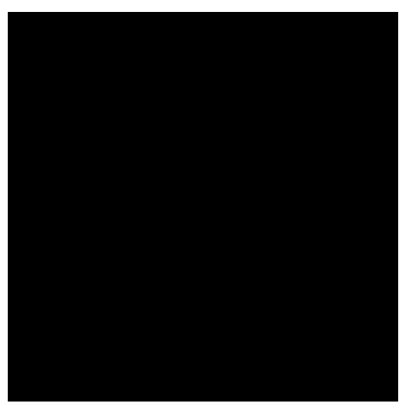
Furthermore, another two images, baboon image with size
, and the all-black figure with size
, are used as the test images as well. The baboon image is shown in
Figure 12 and its histogram is shown in
Figure 13. The all-black figure is shown in
Figure 14 and its histogram is shown in
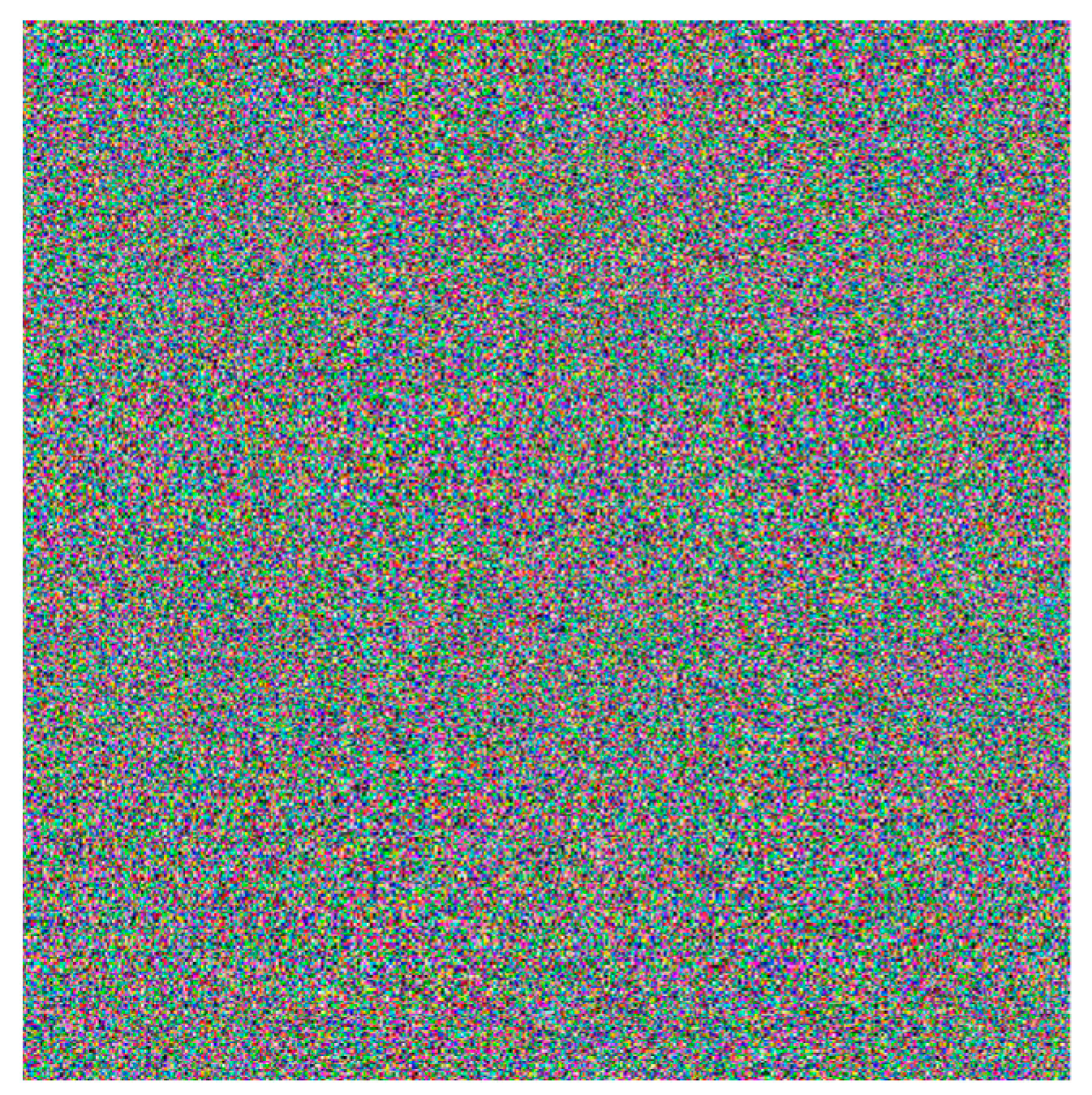
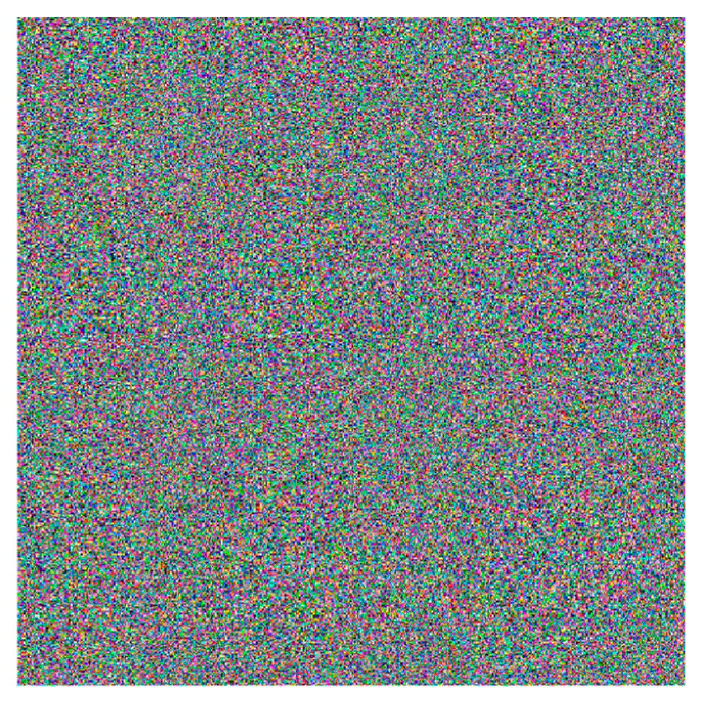
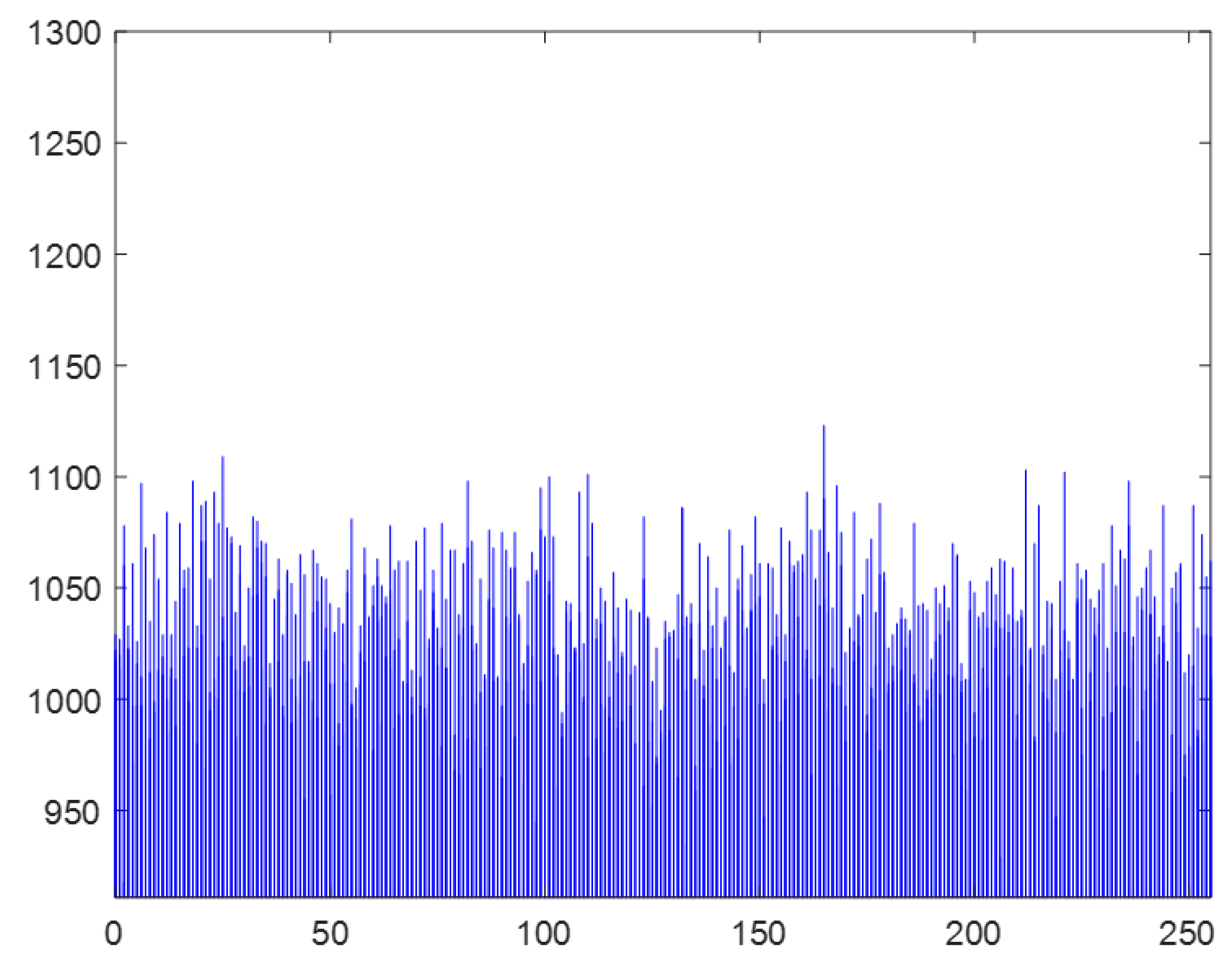
Figure 15. One can obtain the encrypted baboon image and the encrypted all-black image shown in
Figure 16 and
Figure 17, respectively, and the histograms are, respectively, shown in
Figure 18 and
Figure 19. The encrypted image is done by utilizing the above algorithm with the same secret key. Then, we can observe that the histogram of the encrypted baboon image (
Figure 18) and the histogram of the encrypted all-black image (
Figure 19) are flat as well. Eventually, the image encryption algorithm can be applied in the image with any size, and the detailed analysis for the security is discussed in the next section.
Once the encryption is completed, one starts the process of the decryption with decryption information. The file of decryption information includes the system states, the sampling time, the synchronization time, and the encrypted image. The file of decryption information is established in the transmitter and sent to the receiver. Then, by using the proposed synchronization-based communication to obtain the secret key, one performs the decryption algorithm to obtain the decrypted image.
Figure 20 shows the decrypted images.
To show the effectiveness of the encrypted algorithm, the plain image is contrasted with the decrypted image pixel by pixel, and one can get the following result.
Thus, one can know that there is no difference between two images, and the encrypted and decrypted algorithms are feasible.
E. Security analysis
In this section, we analyze the security of the encryption algorithm with three images.
(1) Key space analysis
Key space means the total number of all different keys used in the encryption algorithm. The value of key space must be high so that it can make the brute-force attack ineffective. The secure key in this proposed algorithm is utilized to generate the sampling time for sampling the states, and the sampling time is ranged in . The key space can reach . The valid precision of the initial condition in chaotic systems is set to , so the key space can reach . Thus, the number of different key combinations that can be used are , which is large enough to resist the brute-force attack.
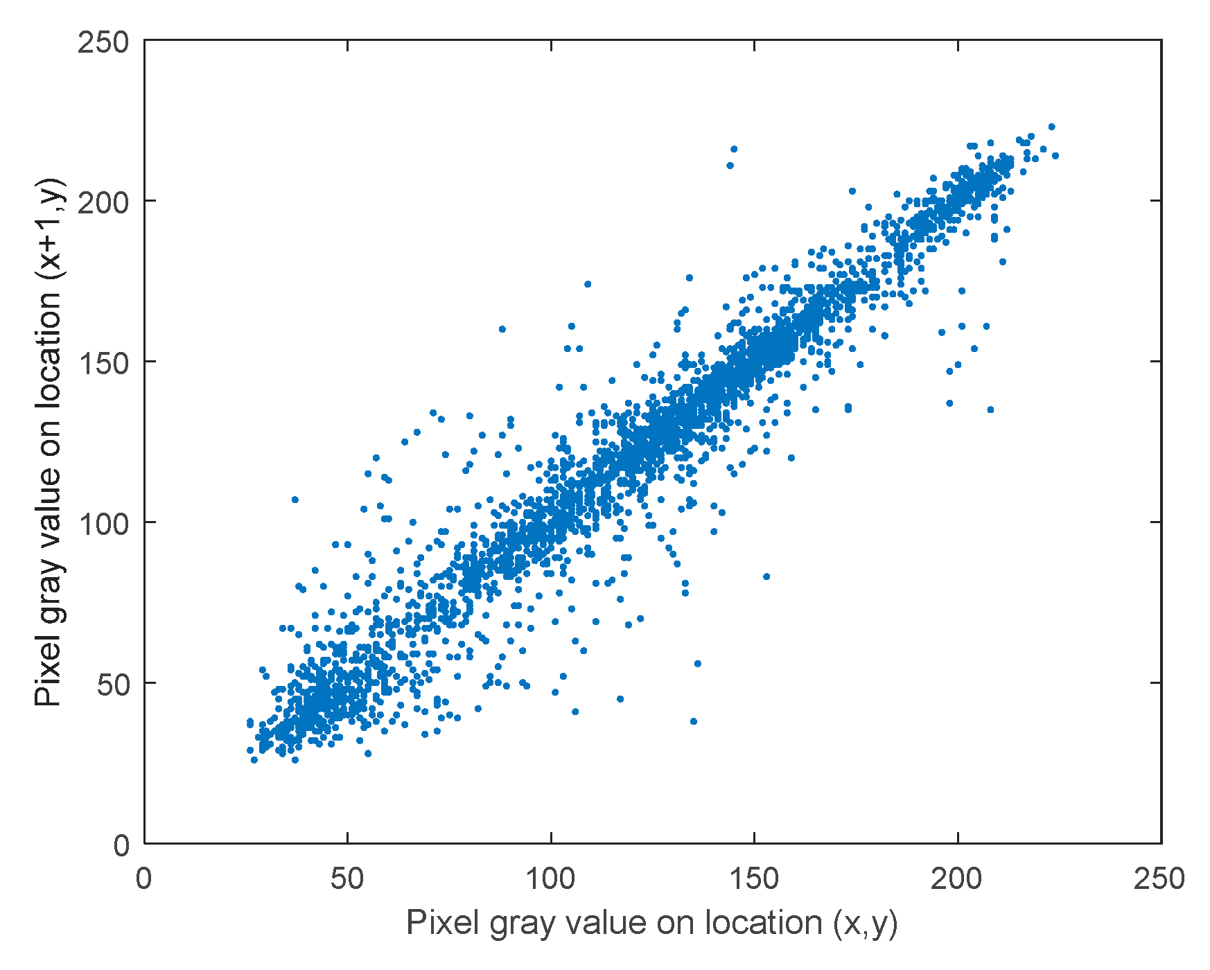
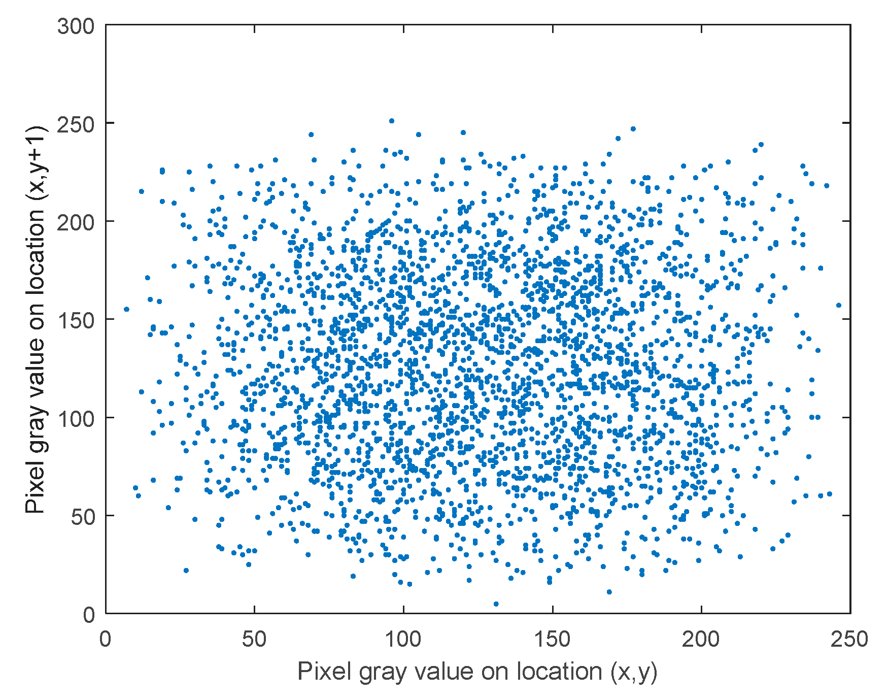
(2) Correlation
Adjacent pixels of an image will always be similar and with a strong correlation. A good image encryption algorithm is able to weaken the correlation of the adjacent pixels. The correlation function of the image is given as follows:
where
,
,
.
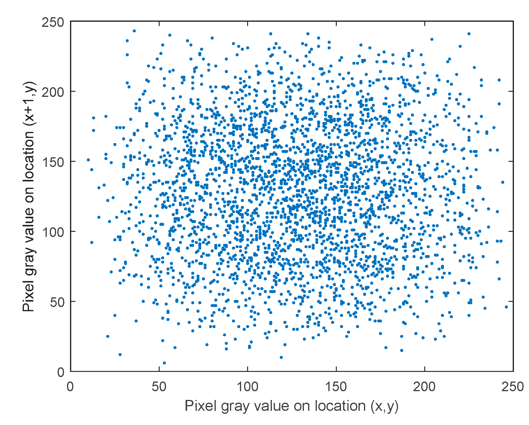
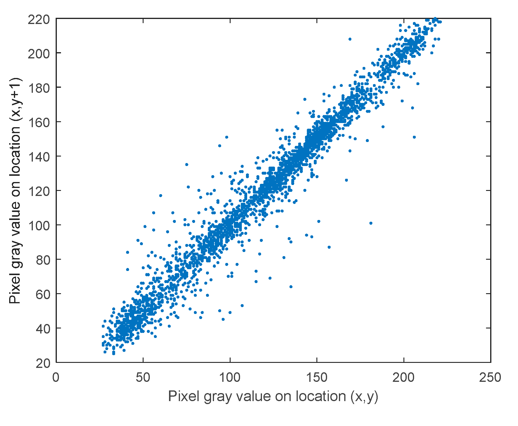
The correlation analysis demonstrates the similarity between two adjacent pixels in the vertical direction and the horizontal directions. The range of the correlation is
. The higher value means the higher correlation. One randomly selects 3000 pairs of the adjacent pixel from the plain image and encrypted image, respectively, to calculate the correlation coefficient. The horizontal correlation of the plain Lena image is shown in
Figure 21 and the horizontal correlation of encrypted Lena image is shown in
Figure 22. The vertical correlation of the plain Lena image is shown in
Figure 23 and the vertical correlation of the encrypted Lena image is shown in
Figure 24. One can find that the correlation of the adjacent pixel weakens after applying the encryption algorithm. The value of the correlation is shown in
Table 1. Then, one can compare the proposed algorithm with the algorithm in [
22] on the encrypted Lena image. One can observe that the correlation coefficient in this paper is smaller than the correlation coefficient in [
22] and this means the encryption algorithm in this paper is much more effective in decreasing the adjacent correlation as wells.
(3) Entropy
The entropy function of an image is given as follows:
where
,
are the numbers of the rows and the columns of the image,
is the pixel value at the
th row and the
th column in the image, and
is the probability of image pixel at the
th row and the
th column. Entropy demonstrates the randomness of the image and the value range in
for an image having 256 scales. The high value of entropy means the encrypted image has a greater amount of randomness. The value of entropy of the proposed algorithm is shown in
Table 2. Comparing the encrypted Lena image in [
22] with the encrypted Lena image in this paper, one can figure out that the entropy of the encrypted Lena image in this paper is larger than that in [
22]. It means the Lena image encrypted by the proposed algorithm can get the higher randomness in the encrypted image.
F. Ability to resist differential attack
The differential attack is a good method to break the proposed encryption algorithm. If the encryption method has good sensitivity and diffusion property to the plain image, it can resist those attacks. There are two indexes to evaluate the diffusion property, the number of pixel changing rate (NPCR) and unified averaged changed intensity (UACI). NPCR implies the change rate between two encrypted images and encrypted from two plain images with only one pixel different. NPCR and the UACI are defined as (42) and (43)
(2)
where
is defined as
.
Here, we encrypt the Lena image, baboon image, and all-black image as
, and change the value of one pixel Lena image, baboon image, and all-black image then encrypt as
. Then, calculate the values of NPCR and UACI, and compare NPCR and UACI of the proposed method with the others [
20,
22] in
Table 3 and
Table 4.
One can find that NPCR applied in color images is over 99% and NPCR applied in the all-black image can be also over 99%. UACI applied in the color images can be over 33% and UACI applied in all black image can approach 33%. The result shows that the proposed encryption algorithm is sensitive to a tiny change in image, even if the change is only in one pixel. The comparison results in
Table 5 reveal that the method proposed in this paper has better results in NPCR and UACI tests. Thus, the proposed encryption algorithm is strong enough to make the differential attack ineffectively.


 ,
, 


