

Energy-Efficient Resource Allocation for D2D-V2V Communication with Load Balancing


College of Information Science and Engineering, Xinjiang University, Urumqi 830000, China
*
Author to whom correspondence should be addressed.
Mathematics 2023, 11(13), 2848; https://0-doi-org.brum.beds.ac.uk/10.3390/math11132848
Submission received: 2 June 2023
/
Revised: 19 June 2023
/
Accepted: 21 June 2023
/
Published: 25 June 2023
(This article belongs to the Special Issue Advanced Algorithms in Wireless Communication and Internet of Things (IoT))
Abstract
:The significance of vehicle-to everything (V2X) communication in ensuring road safety is undeniable. In addition, real-time vehicle communication requires an ample amount of spectrum resources. However, the existing spectrum resources are seriously scarce, and the utilization rate is not high, leading to high delays in V2X communication and other unfavorable factors in the case of fast-moving vehicles, bringing great safety risks to driving. Load balancing is one of the most effective methods to improve spectrum utilization. However, the existing load balancing schemes merely focus on static conditions, with a lack of joint scheduling schemes, which cannot support the communication framework of dynamic V2X. To address both of these issues, in this paper, a new communication method is proposed. In addition, this paper studies a joint load balancing scheme of mobility vehicle-to-vehicle (V2V) and user association under incomplete channel state information (CSI) and realizes the load balancing management of a cross-cell V2X network. An algorithm combining power control and resource allocation mode selection is proposed. In particular, according to different coverage areas, different allocation algorithms are adopted to maximize the overall system efficiency. The simulation results show that this strategy can maintain low latency and effectively improve the system energy efficiency of vehicle users.
Keywords:
vehicle-to-vehicle (V2V) communications; vehicle load balancing; mode selection; energy efficiencyMSC:
94-051. Introduction
V2V is expected to provide safety applications for vehicles, such as collision warning, traffic information prompts and intersection warning [1]. V2V communication has attracted wide attention from researchers in recent years. V2V network topologies based on device-to-device (D2D) communication have become a research hotspot in recent years, as they can offer high reliability and less delays for vehicles [2,3], and provide a high-quality service experience for vehicles during their movement. However, the exponential growth of communication has brought great pressure to cellular networks. Cisco’s report shows that global mobile data traffic may reach 160 eb per month by 2025. With the increasing demands of mobile data, the existing spectrum resources are seriously insufficient, which leads to a serious overload problem [4]. They cannot meet the requirements of safe V2V communication.
At present, many studies have shown that in the coverage area of adjacent base stations (BSs), there is a large gap in peak traffic [5]. For example, in daily study and work, a large number of users are concentrated in some fixed areas, while a few users are located in other areas. This situation will lead to an uneven traffic distribution among cellular networks [6]. This can lead to the further waste of a large amount of spectrum resources, meaning that safe V2V communication cannot be effectively guaranteed. In addition, for vehicle users, due to the high-speed mobility of vehicles, vehicles are sensitive to the transmission scenarios of cellular networks, resulting in highly dynamic topologies of V2X wireless networks [2]; thus, studying dynamic vehicle load balancing strategies in cellular network vehicle communication is a great challenge.
There are other methods to effectively solve the shortage of spectrum resources in safety-related V2V communication. The 3rd Generation Partnership Project (3GPP) Release 14 proposes two resource allocation methods for V2V communication based on the D2D:mode 3 (resource allocation by the evolved node B (eNB)) and mode 4 (resource selection by user equipment (UE) [7]. In mode 3, the UE requests the transmission resources of the eNB, and then the eNB allocates the granted resource blocks (RBs) to the UE for data transmission. Mode 3 is also divided into the following two sub-modes: the dedicated mode, which will not be interfered with by other users when using dedicated RBs for direct communication, and the reuse mode, where vehicular user equipment (VUE) can communicate by reusing RBs occupied by primary user equipment (PUE), which will cause co-channel interference. In mode 4, VUEs independently select resources from the preconfigured unauthorized resource pool [8]. Moreover, mode 4 can provide V2X services in and out of coverage without the eNB [9].
In [10,11], it is proved that different areas (residential areas, commercial areas, transportation areas, entertainment areas and comprehensive areas) have different transportation modes at different time points and in different peak periods. In order to make rational use of spectrum resources and improve their utilization rate, it is critical for vehicles to achieve load balance among different BSs [4].
With regard to load balancing, [12] considers an ultra-dense small cell network, which balances the cellular traffic among cells through D2D routing and maximizes the sum rate of the system. In [4], through a D2D load balancing mechanism, the D2D communication between cells was used to realize the transfer of traffic between different cells, and explore the relationship between traffic demand and D2D overhead. The authors of [10,11] used intelligent user association to dynamically associate users with different BSs and realize load and flow balance management.
It has been found that D2D load balancing schemes and user association schemes have different effects on different time scales. By using a smart user association scheme for large time scales and using a D2D scheme for small time scales, better results can be achieved. In daily cellular networks, adjacent BSs often produce overlapping coverage areas [13]. When the VUE receiver (VUR) or VUE transmitter (VUT) is located in the overlapping area and the VUT or VUR is located in the non-overlapping area, a D2D scheme is suitable, and when both the VUR and VUT are located in the overlapping area, a user association scheme is suitable, which can achieve better network performance. Researchers seldom consider combining D2D with user association to achieve load balancing and energy efficiency improvement. At the same time, due to the mobility of vehicles, the topology of vehicle wireless networks is highly dynamic, which will introduce the Doppler effect on vehicle links. It is difficult to obtain accurate CSI of vehicle links. Therefore, the above works are not directly applicable to V2X networks since they do not consider the chief factor of the Doppler effect [14,15,16].
The authors of [17,18,19] discussed the maximization of V2X system throughput. The authors of [17] studied a resource allocation scheme based on an interference hypergraph; and the authors of [18] put forward a new v2v resource allocation scheme, which improves the reliability and delay of vehicles; and the authors of [19] put forward a resource allocation method based on deep reinforcement learning to maximize throughput. The author of [20,21] proposed a novel Reverse Auction-based Computation Offloading and Resource Allocation Mechanism, which minimizes the cost of the Cloud Service Center. The author of [22,23,24] improved the reliability and spectral efficiency of V2X communication through deep learning. However, due to the increase in the number of vehicles and the deterioration of traffic conditions, the energy consumption of vehicle networking will increase greatly, and the total fuel consumption may increase by 120% [25], which will aggravate energy consumption and trigger severe environmental issues. The methods used to improve the energy efficiency of vehicle systems have not been well studied.
In addition, the shortcomings of the work discussed above are as follows:
- Only static user load balancing and resource allocation were studied, which cannot meet the requirements of the communication framework of dynamic V2X.
- There is a lack of research on D2D and user association joint scheduling.
- Therefore, in this paper, we considered a joint load balancing scheme of mobility V2V and user association under incomplete CSI, through a new method for power control and overlapping area and non-overlapping area mode selection, to further improve the overall energy efficiency of the system.
- In view of the above problems, the contributions of this paper are as follows:
- This paper mainly studies the load balancing scheme between two adjacent BSs, and a dynamic energy efficiency optimization mechanism of joint load balancing across cells is proposed. In different cellular systems, the spectrum traffic will fluctuate unevenly, and there will be a load balancing problem between two cells (one cell’s spectrum resources are not fully utilized, and the other cell’s spectrum resources are seriously insufficient). In order to rationally utilize spectrum resources and improve their utilization rate, a dynamic load balancing strategy for vehicles is proposed in combination with D2D-V2V and user association schemes.
- According to the proposed system model, the mathematical expression is an NP-hard problem, and a method of joint power control and resource allocation mode selection is proposed. For the power control problem, a power control method based on Dienkelbach [26] is proposed, which maximizes the energy efficiency of a single VUE. An iterative algorithm for power control optimization is designed, which can significantly reduce the computational complexity. Using the obtained results, the original optimization problem is further simplified to the problem of resource allocation mode selection.
- For the resource allocation problem, according to the coverage situation of different real BSs, two resource allocation mode selection algorithms are proposed. The unoverlapped region resource allocation algorithm (URRAA) is used in non-overlapping areas, and the overlapped region resource allocation algorithm (ORRAA) is used in overlapping areas. These two algorithms optimize the sum of energy efficiency through three different modes of joint resource scheduling.
- The main contents of the remaining chapters of the paper are as follows: Section 2 introduces the system model and the modeling and definition of the formulas; Section 3 focuses on the modeling and definition of energy efficiency under the background of V2X communication; Section 4 describes the power control mode selection algorithm; Section 5 evaluates and analyzes the system performance of the proposed algorithm; finally, Section 6 briefly summarizes our main work and presents some conclusions.
2. System Model
2.1. System Model for V2X Network
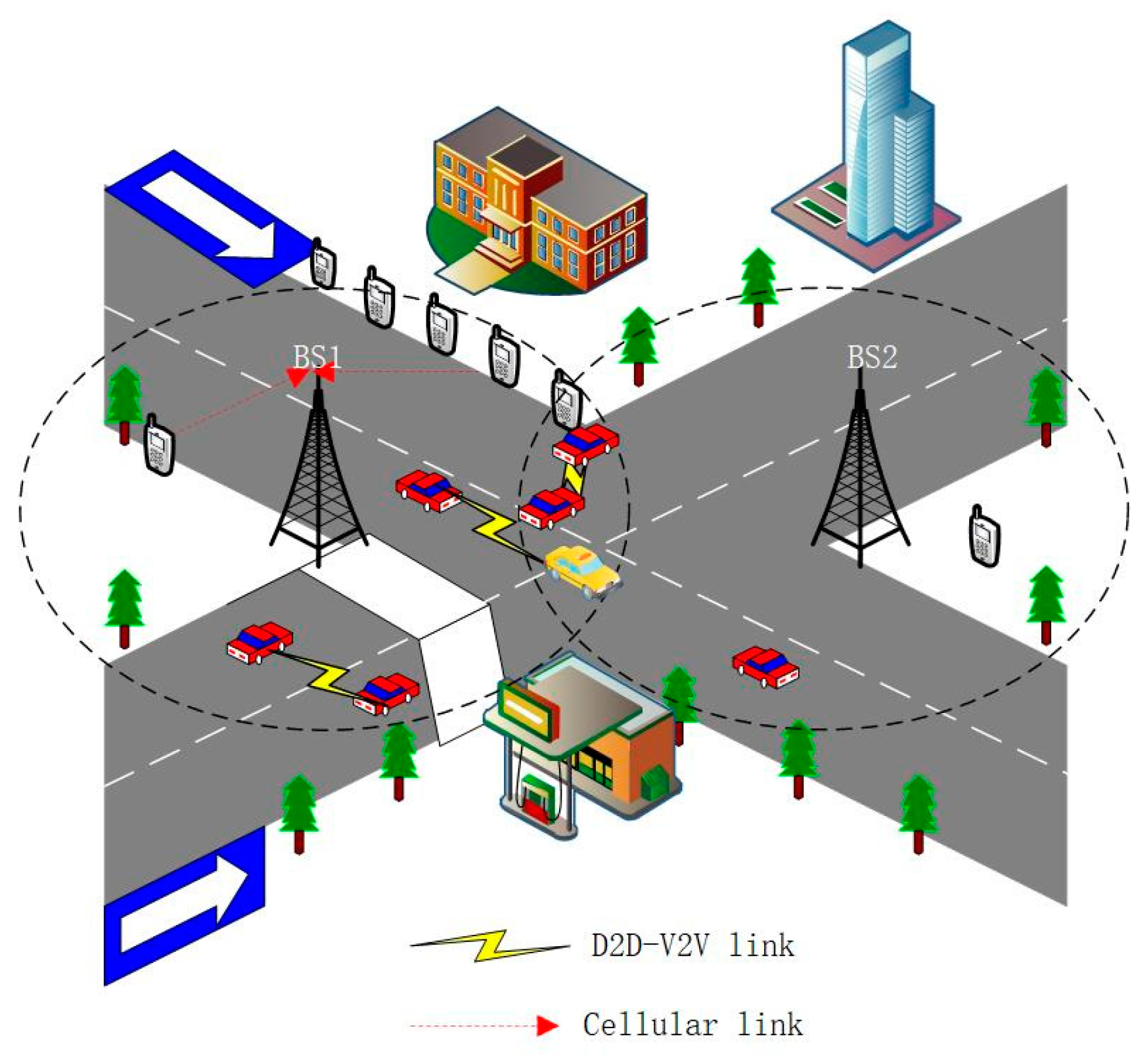
The V2V communication network based on D2D is shown in Figure 1. A V2X network based on an urban environment is proposed.
Without losing generality, we considered two cell scenarios, in which the BS is a circular coverage area with radius R; BS1 belongs to a cellular structure with busy user visits, and BS2 belongs to a cellular structure with less user visits (there are unused spectrum resources). We divided the BS1 users into two different parts: first, there are users in the BS overlapping coverage area (including all vehicle user pairs in the coverage area, one vehicle in the non-overlapping area of BS1, and one vehicle in the overlapping area), along with other users (vehicle user pairs in the non-overlapping area of BS1).
On the premise of orthogonal frequency division multiple access (OFDMA) [27], each PUE is assigned a unique (orthogonal) channel in advance to reduce the interference between PUEs. At the same time, each pair of VUEs multiplexes one and only one subchannel.
The following definitions are used: there are vacant licensed RBs and U vacant unlicensed RBs in BS1. is the set of vacant licensed RBs in BS1, and is the set of vacant unlicensed RBs. There are vacant licensed RBs in BS2. is the set of vacant licensed RBs in BS2. is the set of PUEs in BS1, and is the set of PUEs in BS2. is the set of VUEs in BS1, is the set of vehicle users in non-overlapping areas, is the set of vehicle users in overlapping areas and Ny = N − Nz represents the number of VUEs in the overlapping coverage area of BS1.
In addition, we assume that in all lanes, the VUE transmitters uniformly fall in different positions in the lanes by adopting the spatial Poisson process. In order to maintain a safe distance between VUE pairs, the number of VUE pairs varies according to different speeds, and the faster the vehicle speed, the lower the number of VUE pairs. The cluster distribution model [28] was considered for each VUE pair, so as to ensure normal communication and connection reliability between the VUR and VUT. Due to road congestion in urban traffic peak hours, we approximately assumed that each VUT and its VUR have the same movement direction and speed, and the vehicle density fitting is as follows [7]:
where is the absolute vehicle speed, km/h. In this model, communication between the VUR and VUT is realized through D2D technology. VUEs communicate in different modes (mode 3 or mode 4) according to different situations. Mode 3 can be divided into special mode or reuse mode. In the reuse mode, VUEs reuse the uplink cellular resource RBs [28], where each VUE pair can occupy one RB, and each RB can be occupied by at most one VUE. The meanings of the key numeric symbols are shown in Table 1.
2.2. Communication Channel Model for V2X Network
In the channel modeling, we considered both large-scale fading and small-scale fading, which are independent block fading channels [29]. For example, is defined as the channel gain between VUT and its corresponding receiver, represents the channel gain of the non-overlapping area, and represents the channel gain of the overlapping area, which can be expressed as
where represents the large-scale fading effect of VUE and represents the small-scale fading effect. represents the path-loss exponent and indicates the distance between the transmitting and receiving ends of the vehicle.
In each TTI, other large-scale fading effects, such as the shadowing effect, are approximately constant, which can be obtained by eNB. However, for small-scale fading, different analyses can be used for different situations. Considering the links directly connected to the eNB shown in Figure 1 and the and of VUE , we assume that the small-scale fading information of these links can be obtained by the eNB and distributed independently and identically according to [2]. The reasons are as follows:
- The Doppler effect will significantly affect small-scale fading, but the direction and speed of motion between the VUR and VUT are the same, meaning the influence of the Doppler effect can be ignored.
- In the V2V establishment stage, the channel information of each VUE pair is obtained by the eNB.
The interference link from the PUE transmitter to the VUE receiver is given as [29]
Because the PUE transmitter is relatively stationary or only moves slightly, while the VUE receiver moves rapidly, there will be a large relative movement speed between them, which will lead to a serious Doppler frequency shift effect and imperfect CSI of , which will have a great impact on the small-scale fading [30], and the eNB will not be able to obtain accurate knowledge of the small-scale fading. In this case, [30] proves that the first-order Gaussian–Markov process can provide more accurate modeling. The modeling of is as follows:
where represents the estimated channel gain, represents the distribution of the small-scale fading and estimation error, and are independently and identically distributed and obey and the coefficient quantifies the channel correlation of two consecutive time slots, where is given as [31]
where is the first type of zero-order Bessel function; represents the maximum Doppler frequency shift; , where indicates the vehicle speed, is the carrier frequency, and ; is the period feedback latency.
2.3. Data Transmission and Energy Consumption for V2V Communication
When VUE is in dedicated mode or mode 4, it will not be interfered with by the PUE. Tts signal-to-interference-plus-noise -ratio (SINR) and instantaneous data rate can be defined as
where is the transmission power of VUE and is additive white Gaussian noise. VUE multiplexes the resource block of PUE ; its SINR and data rate can be expressed as
where indicates the transmission power of VUE in reuse mode, and indicates the transmission power of PUE .
In the same way, when PUE does not share an RB with VUE , its SINR and data rate can be expressed as
where represents the transmission power of PUE when there is no interference signal signal. However, when the resource block RB of PUE is reused by VUE , the SINR and data rate of PUE can be expressed as
V2X communication requires a much stricter delay and reliability than traditional cellular communication. The minimum SINR requirement of V2X communication needs to be guaranteed. The SINR needs to be above a certain threshold , as follows:
The energy consumed by the I-th VUE link is expressed as
The total energy consumed is
where denotes the fixed circuit power of both the transmitter and the receiver of the I-th VUE link, and is a factor accounting for the transmit amplifier efficiency.
3. Problem Formulation
For different communication modes, we define different binary indicator matrices, in which is the autonomous resource selection mode, is the dedicated mode and is the reuse mode. We assumed that each VUE can only choose one communication mode; here, its binary indicator variable was set to 1, and the other indicator variables were set to 0.
The throughput of communication in the autonomous selection mode is
The system throughput in the dedicated mode is
The throughput of the vehicle system in the reuse mode is
The total vehicle throughput is
At the same time, due to the rapid mobility of vehicles and the change in communication environment, the current V2X communication practice also has potential deficiencies in energy efficiency (EE) [6]. Therefore, our goal was to maximize the energy efficiency of vehicle systems. The optimization problem is shown in Formula (21).
In the optimization problem (21), represents the transmission power of the VUE in autonomous resource selection mode, represents the transmission power in dedicated mode, represents the transmission power in reuse mode and represents the transmission power of the PUE being reused when the VUE is in reuse mode.
Formula (21b) stipulates that the number of VUEs using mode 4 for communication must be less than or equal to the total number of unauthorized RBs. In the same way, Formula (21c) stipulates that the number of VUEs using the dedicated mode for communication must be less than or equal to the total number of authorized RBs. Formula (21d) indicates that a VUE pair can only work in one resource allocation mode at most, and Formula (21e) indicates that each RB can only be shared by one PUE and one VUE pair.
In order to meet the data transmission requirements of the PUE and VUE, we used the constraints (21f) and (21g) to limit the minimum SINR requirements of the PUE and VUE. The maximum transmission power of the PUE and VUE is restricted by (21h) and (21i), respectively.
Because the optimization formula contains binary variables and continuous variables , the optimization problem is NP-hard, and it is difficult to obtain the optimal solution in polynomial time. Therefore, we solved the optimization problem through a distributed algorithm, i.e., power control and mode selection. We optimized the power in three modes, and then carried out the mode selection algorithm after obtaining the optimal power allocation.
4. Power Control Mode Selection Algorithm
4.1. Power Control Algorithm Based on DIENKEBACH
In this section, we calculate the optimal power allocation value of a single VUE in different modes and propose a power allocation algorithm to reduce the complexity of the problem. When in mode 4 (unlicensed spectrum), the energy efficiency optimization formula of a single VUE can be expressed as
According to the principle of non-linear programming, the objective function of the above problem can be expressed as
The form of the optimization problem is as follows:
Therefore, the above optimization problem is transformed into
This problem is solvable.
We aimed to verify that the above problem is a standard definition of a convex optimization problem.
By finding the second derivative of Formula (26), the second-order judgment condition of the convex function can be obtained. It is easy to prove that is a concave function, meaning that constraint 1 of the above problem is a concave function, and constraint 2 is a linear function, which is a standard convex optimization problem [32].
When in reuse mode, the optimization formula can be expressed as
The solution method is the same as the above, and the above problem can be transformed into
Define function as
Define function as
The second derivative of and can be found to be less than or equal to 0. The objective function and constraint function of the optimization problem are concave functions, and the other constraints are linear functions, which is a standard convex optimization problem. The MATLAB convex optimization toolkit can be used to find the optimal solution and the optimal power allocation.
The specific process is shown in Algorithm 1.
| Algorithm 1: Power control algorithm based on Dienkelbach |
| 1: Initialize , . And set the precision error as ; |
| 2: Get according to Formula (27); |
| 3: Get according to Formula (24); |
| 4: Compared with ; If , then through (23), get , jump to step 6, otherwise, skip to step 5; |
| 5: If , then get through (23). Go back to step 2; |
| 6: Power control algorithm is finished. Obtain ; |
4.2. Mode Selection Algorithm
In order to improve the energy efficiency of the whole system, it is necessary to switch as many V2V pairs as possible to unauthorized and dedicated modes. If one V2V pair works in the dedicated mode, it will not produce co-channel interference, and will provide additional orthogonal spectrum resources for other VUE pairs, which will significantly reduce the overall interference of the system and provide more multiplexing opportunities for VUE pairs in the multiplexing mode.
We substituted and obtained through the power allocation algorithm in different modes into Formula (21). In this way, Formula (21) can be simplified to Formula (31).
Formula (31) only contains binary indicator variables, namely . Therefore, Formula (31) is a 0–1 integer programming problem. In order to obtain the optimal system energy efficiency, we propose a joint resource scheduling method with different communication modes in different coverage areas.
4.2.1. Unoverlapped Region Resource Allocation Algorithm
As shown in Algorithm 2, in step 1, in order to obtain the best energy efficiency value, VUE users in the left non-overlapping area preferentially choose to work in mode 4. The VUE can independently select appropriate resources for communication according to the mapping relationship between the geographical area and resource pool or cognitive radio mode. When the VUE selects suitable unauthorized RBs for communication, the VUE exchanges scheduling information with other VUEs through broadcasting and deletes the unauthorized RBs from the resource pool. This process does not depend on the control of the core network and eNB. Upon detecting that there are no idle unauthorized RBs, the eNB will receive the report information of the VUE, and step 1 ends.
In step 2, the remaining VUEs that are not communicating will switch to the dedicated mode. In the dedicated mode, the eNB is responsible for uniquely allocating authorized RBs to the VUE. Once the VUE occupies an RB, the eNB deletes the used RB from the idle licensed RB set. The algorithm terminates when all idle licensed RBs are allocated or all VUEs can communicate through the obtained free authorized RBs. Otherwise, the remaining VUEs will be able to transfer to reuse mode.
and can be obtained by executing the first two steps of the URRAA, and Formula (31) can be further simplified to Formula (32). Formula (32) only contains a binary indicator variable, , which is equivalent to solving the problem concerning which PUE resource block should be reused by the VUE. The matching algorithm was analyzed as follows:
For the analysis of the matching algorithm and in order to meet the Qos requirements of VUE users and the information rate requirements of PUE users, the matching problem between the VUE and its reusable PUE can be transformed into a marriage matching problem, because this not only ensures the needs of both parties, but also achieves a better energy efficiency improvement. Both the improved Gale–Shapley (GS) algorithm and Hungarian algorithm can solve the problem of stable matching between two sets, and the number of PUEs and VUEs can be uncertain, but the EE improvement of the improved GS algorithm is not significant. Meanwhile, the Hungarian algorithm can achieve stable matching between the VUE and PUE and obtain a better EE value to meet the demands for minimal delays among vehicles. Therefore, the Hungary algorithm was adopted in this paper.
| Algorithm 2: Unoverlapped region resource allocation algorithm |
| 1: Vz represents the set of unmatched VUEs; |
| 2: Vr represents the set of VUEs sharing same RBs with PUEs; |
| 3: while Vz do; |
| 4: Step 1: Autonomous Resource Selection Mode Selection |
| 5: if then; |
| 6: VUE gets access to vacant unlicensed RB by sensing and broadcasting technology; |
| 7: ; |
| 8: Remove RB from vacant unlicensed RBs set ; |
| 9: Remove VUE from Vz; |
| 10: Step 2: Dedicated Mode Selection |
| 11: else if then; 12: VUE gets access to vacant licensed RB Fi by the scheduling of eNB; 13: ; 14: Remove RB Fi from vacant licensed RBs set ; 15: Remove VUE from Vz; 16: else if = & = then; 17: The Hungarian algorithm obtains the optimal match; 18: end if; 19: end while; 20: URRAA algorithm is finished. Obtain , and . |
4.2.2. Overlapped Region Resource Allocation Algorithm
As shown in Algorithm 3, in step 1, because VUE users in overlapping areas can adopt the load balancing scheme of D2D and user joint scheduling proposed in this paper, they can dynamically select the spectrum resources of their own base station and neighboring base stations according to the SINR requirements, so as to obtain the optimal system energy efficiency. This leads to step 2.
In step 2, the remaining uncommunicated VUEs will use the multiplexing mode for communication. Because the first base station is a congested base station, and there are many users, in order to guarantee the service quality of PUE users, all users in the overlapping area reuse the spectrum resources of the second PUE users for communication. In this paper, the Hungarian algorithm was used to match the best PUEs for the vehicles, and one-to-one matching was adopted.
| Algorithm 3: Overlapped region resource allocation algorithm |
| 1: Vy represents the set of unmatched VUEs; |
| 2: Vr represents the set of VUEs sharing same RBs with PUEs; |
| 3: while Vy do; |
| 4: Step 1: Base Station Selection |
| 5: if then; |
| 6: VUE gets access to vacant unlicensed RB by sensing and broadcasting technology; |
| 7: ; |
| 8: Remove RB from vacant unlicensed RBs set ; |
| 9: Remove VUE from Vy; |
| 10: else if then; |
| 11: In dedicated mode, Calculate the best SINR of RBs in BS1 used by VUE ; |
| 12: Calculate the best SINR of RBs in BS2 used by VUE ; 13: if ; 14: Select RBs of BS1; 15: else if; 16: Select RBs of BS2; 17: ; 18: Remove RB () from vacant licensed RBs set ; 19: Remove VUE from Vy; 20: else if = &(,) = then; 21: Step 2: Resource Allocation 22: The Hungarian algorithm obtains the optimal match; 23: end if; 24: end while; 25: ORRAA algorithm is finished. Obtain , and . |
5. Performance Analysis
In this section, we evaluate the performance of the proposed algorithm. We followed the city case simulation in 3GPP TR36.885 [7] (density, speed, vehicle channel, V2V data traffic, etc.). The vehicle position uniformly falls in different positions in the lane through the spatial Poisson process. In order to verify the performance of the mathematical model proposed in this paper, MATLAB 2018a was used to conduct simulation experiments under the configuration of Intel (R) Core (TM) [email protected] GHz, RAM8GB and Windows10 Professional.
The main simulation parameters are presented in Table 2. In addition, we simulated and tested the average EE performance more than 1000 times.
In order to evaluate the performance of the proposed algorithm, the results of this algorithm were compared with those of an exhaustive algorithm, an algorithm without load balancing (WLB) and the improved GS algorithm (IGS).
Figure 2 shows a comparison of the energy efficiency values of the different algorithm systems. It can be clearly observed that the load balancing strategy proposed in this paper improved the energy efficiency of the vehicles. It was significantly superior to the other algorithms, and its performance was close to that of the optimization algorithm, with an average system performance of 97% of that of the exhaustive algorithm. This is because this paper used spectrum resources that are not fully utilized in neighboring cells, meaning that more vehicle users can communicate in the special mode of the authorized mode without interference from the main users, and the channel condition information is better, enabling the energy efficiency value of the system to increase. Furthermore, with the increase in VUE distance, the energy efficiency of the system showed a downward trend, because with the increase in distance, the path loss increased significantly, and the overall energy efficiency decreased. Energy efficiency increased by an average of 17%. With the increase in the number of resource blocks, the energy efficiency of the system increased accordingly, because the number of vehicles that can be used in special mode also increased, and more vehicles were used in dedicated mode in the overlapping areas, which significantly improved the energy efficiency of the system.
Figure 2 proves that the energy efficiency of this system is close to 97% of the system performance of the exhaustive algorithm, and as shown in Figure 3, the time efficiency of this algorithm was significantly better than that of the exhaustive algorithm, which can better meet the requirements for minimal delays among vehicles. Additionally, with the increase in PUE number, the time of the exhaustive algorithm increased, but the time change of this algorithm was not significant, which shows that the performance of this algorithm is close to that of the exhaustive algorithm. Moreover, the time efficiency was greatly reduced, and the running speed of the algorithm did not slow down with the increase in the number of users.
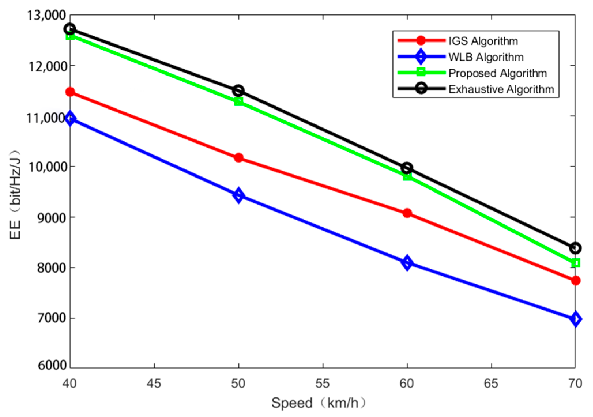
In this scheme, according to Formula (1), different vehicle speeds and different vehicle densities lead to different numbers of VUE pairs, and different VUE pairs will also have a great impact on the system energy efficiency.
It can be observed in Figure 4 that, with the increase in vehicle speed, the energy efficiency of the system showed a downward trend. This is because the vehicle modeling in this paper obeyed the spatial Poisson distribution, the vehicle density was 0 and the number of vehicles was determined by the vehicle speed, that is, with the increase in vehicle speed, the number of vehicles and the energy efficiency of the system will decrease.
As shown in Figure 5, we compared the energy efficiency of the system with the iteration times of the proposed algorithm. It can be observed in the figure that the energy efficiency converged within a small number of iterations and basically reached the convergence state in only two steps. The convergence speed was faster, and by comparing the results of the algorithms with or without load balancing, it can be observed that the energy efficiency of the load balancing algorithm in this paper was obviously better than that of the algorithm without load balancing.
It can be observed in Figure 5 above that the iterative convergence speed of the power control algorithm in this paper was faster, and as shown in Figure 6, the energy efficiency of the algorithm with power control in this paper was significantly improved compared with the algorithm without power control, because the power control algorithm in this paper can iteratively find the power value that makes the energy efficiency of a single VUE system optimal, and can significantly reduce the interference from the main users. Moreover, with the increase in the number of V2V pairs, the accumulated energy efficiency trend will be better than that of the algorithm without power control.
In Figure 7, with the increase in the number of primary users, the energy efficiency value of the vehicles decreased. This is because the number of vehicles communicating in dedicated mode decreased, which were interfered with by the primary users, and the energy efficiency value decreased. Moreover, the performance of the algorithm system in this paper was better than that of the case without load balancing.
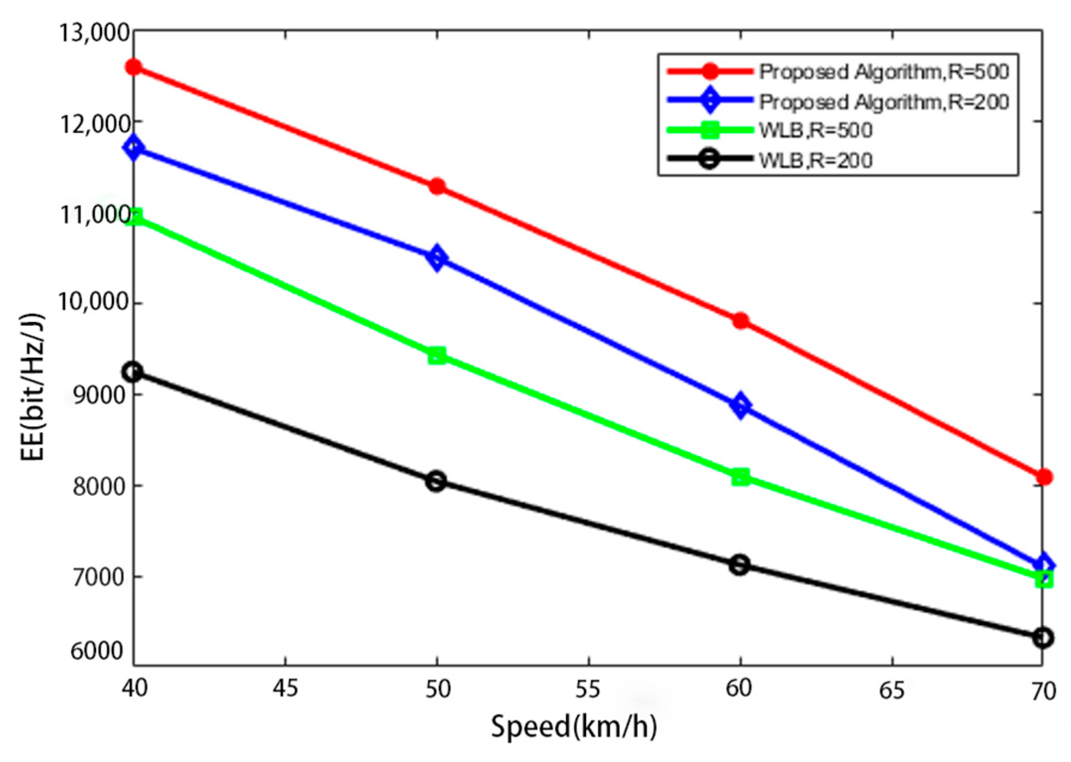
As shown in Figure 8, the energy efficiency of the system with a radius of 500 was obviously higher than that with a radius of 200. This is because when the radius is small, the overlapping area of two base stations will be reduced, the number of vehicles in the overlapping area will be reduced with the same number of vehicles, and the number of vehicles that can reasonably utilize the spectrum resources of BS2 will also be reduced, meaning the system energy efficiency will be reduced. However, regardless of the radius, the system energy efficiency with load balancing was always higher than that without load balancing.
The algorithm in this paper makes rational use of spectrum resources near the overlapping area, and the number of all BS2 primary users will have an impact on the energy efficiency of the vehicle user system in BS1. As shown in Figure 9, with the increase in the number of BS2 primary users, the system energy efficiency declined because the number of vehicles available for the special mode in the overlapping area decreased, and the system energy efficiency decreased to a certain extent. However, under the algorithm without-load balancing, the system energy efficiency was not affected by the main users in BS2.
6. Conclusions
In this paper, a joint scheme of mobile vehicle load balancing was proposed, and a new method of power control and resource allocation mode selection was presented. The joint scheme can significantly improve the system energy efficiency, meet the requirements of vehicle users for spectrum resources and minimal delays, and support centralized/distributed hybrid V2X communication and safety-related V2X services. By considering different resource allocation modes, we proposed a power control strategy to calculate the optimal power allocation value of a single VUE in different modes and at the same time, reduce the reuse of the same channel interference by the VUE and PUE, thereby improving the overall energy efficiency. We proposed two new algorithms, the URRAA and ORRAA, to realize resource allocation in different regions. The simulation results showed that, compared with the other schemes, our proposed scheme can not only significantly improve the energy efficiency of VUEs, but that it can also meet the demands for minimal delays among vehicles.
Author Contributions
Conceptualization, J.B.; methodology, J.B.; software, J.B. and X.Q.; validation, J.B., X.Q.; formal analysis and investigation, J.B.; Investigation, J.B.; resources, J.B., and Z.J.; Data curation, J.B.; writing—original draft preparation, J.B.; writing—review and editing, J.B., X.Q and Z.J.; All authors have read and agreed to the published version of the manuscript.
Funding
This research was funded by: “Research and Development of Key Technologies and Application Demonstration of Integrated Food Data Supervision” Platform in Xinjiang Region. The funded project number is: 2020A03001-2.
Institutional Review Board Statement
Not applicable.
Informed Consent Statement
Not applicable.
Data Availability Statement
Not applicable.
Conflicts of Interest
The authors declare no conflict of interest.
References
- Qian, L.P.; Wu, Y.; Zhou, H.; Shen, X. Non-orthogonal multiple access vehicular small cell networks: Architecture and solution. IEEE Netw. 2017, 31, 15–21. [Google Scholar] [CrossRef]
- Li, X.; Ma, L.; Xu, Y.; Shankaran, R. Resource allocation for D2D based V2X communication with imperfect CSI. IEEE Internet Things J. 2020, 7, 3545–3558. [Google Scholar] [CrossRef]
- Sun, G.; Boateng, G.O.; Ayepah-Mensah, D.; Liu, G.; Wei, J. Autonomous Resource Slicing for Virtualized Vehicular Networks With D2D Communications Based on Deep Reinforcement Learning. IEEE Syst. J. 2020, 14, 4694–4705. [Google Scholar] [CrossRef]
- Deng, L.; He, Y.; Zhang, Y.; Chen, M.; Li, Z.; Lee, J.Y.B.; Zhang, Y.J.A.; Song, L. Device-to-device load balancing for cellular networks. IEEE Trans. Commun. 2018, 67, 3040–3054. [Google Scholar] [CrossRef] [Green Version]
- Xu, F.; Li, Y.; Wang, H.; Zhang, P.; Jin, D. Understanding mobile traffic patterns of large scale cellular towers in urban environment. IEEE/ACM Trans. Netw. 2017, 25, 1147–1161. [Google Scholar] [CrossRef] [Green Version]
- Moutsinas, G.; Guo, W. Probabilistic Stability of Traffic Load Balancing on Wireless Complex Networks. IEEE Syst. J. 2020, 14, 2551–2556. [Google Scholar] [CrossRef] [Green Version]
- TR 36.885 V0.5.0; Third Generation Partnership Project (3GPP), Technical Specification Group Radio Access Network, Study on LTE-Based V2X Services, Release 14. 3GPP: Sophia Antipolis, France, February 2016.
- Rafael, M.; Gozalvez, J. LTE-V for Sidelink 5G V2X vehicular communications: A new 5G technology for short-range vehicle-to-everything communications. IEEE Veh. Technol. Mag. 2017, 12, 30–39. [Google Scholar]
- Li, X.; Ma, L.; Shankaran, R.; Xu, Y.; Orgun, M.A. Joint power control and resource allocation mode selection for safety-related v2x communication. IEEE Trans. 2019, 68, 7970–7986. [Google Scholar] [CrossRef]
- Qin, Z.; Yue, X.; Liu, Y.; Ding, Z.; Nallanathan, A. User association and resource allocation in unified NOMA enabled heterogeneous ultra dense networks. IEEE Commun. 2018, 56, 86–92. [Google Scholar] [CrossRef] [Green Version]
- Guan, X.; Huang, Y.; Dong, C.; Wu, Q. User Association and Power Allocation for UAV-Assisted Networks: A Distributed Reinforcement Learning Approach. Chin. Commun. 2020, 17, 110–122. [Google Scholar] [CrossRef]
- Zhang, H.; Song, L.; Zhang, Y. Load balancing for 5G ultra-dense networks using device-to-device communications. IEEE Trans. Wireless Commun. 2018, 17, 4039–4050. [Google Scholar] [CrossRef]
- Hasan, M.M.; Kwon, S. Cluster-based load balancing algorithm for ultra-dense heterogeneous networks. IEEE Access 2020, 8, 2153–2162. [Google Scholar] [CrossRef]
- Xiao, H.; Zhu, D.; Chronopoulos, A.T. Power Allocation With Energy Efficiency Optimization in Cellular D2D-Based V2X Communication Network. IEEE Trans. Intell. Transp. Syst. 2020, 21, 4947–4957. [Google Scholar] [CrossRef]
- Walter, M.; Shutin, D.; Schmidhammer, M.; Matolak, D.W.; Zajic, A. Geometric Analysis of the Doppler Frequency for General Non-Stationary 3D Mobile-to-Mobile Channels Based on Prolate Spheroidal Coordinates. IEEE Trans. Veh. Technol. 2020, 69, 10419–10434. [Google Scholar] [CrossRef]
- Ding, Y.; Huang, Y.; Tang, L.; Qin, X.; Jia, Z. Resource Allocation in V2X Communications Based on Multi-Agent Reinforcement Learning with Attention Mechanism. Mathematics 2022, 10, 3415. [Google Scholar] [CrossRef]
- Chen, C.; Wang, B.; Zhang, R. Interference Hypergraph-Based Resource Allocation (IHG-RA) for NOMA-Integrated V2X Networks. IEEE Internet Things J. 2019, 6, 161–170. [Google Scholar] [CrossRef]
- Abbas, F.; Fan, P.; Khan, Z. A novel low-latency V2V resource allocation scheme based on cellular V2X communications. IEEE Trans. 2019, 20, 2185–2197. [Google Scholar] [CrossRef]
- Zhang, X.; Peng, M.; Yan, S.; Sun, Y. Deep Reinforcement Learning Based Mode Selection and Resource Allocation for Cellular V2X Communications. IEEE Internet Things J. 2020, 7, 6380–6391. [Google Scholar] [CrossRef] [Green Version]
- Zhou., H.; Jiang, K.; He, S.; Min, G.; Wu, J. Distributed Deep Multi-Agent Reinforcement Learning for Cooperative Edge Caching in Internet-of-Vehicles. IEEE Trans. Wirel. Commun. 2023. [Google Scholar] [CrossRef]
- Zhou, H.; Wu, T.; Chen, X.; He, S.; Guo, D.; Wu, J. Reverse Auction-Based Computation Offloading and Resource Allocation in Mobile Cloud-Edge Computing. IEEE Trans. Mob. Comput. 2022. [Google Scholar] [CrossRef]
- Deng, D.; Wang, C.; Wang, W. Joint Air-to-Ground Scheduling in UAV-Aided Vehicular Communication: A DRL Approach With Partial Observations. IEEE Commun. Lett. 2022, 26, 1628–1632. [Google Scholar] [CrossRef]
- Du, Z.; Wu, C.; Yoshinaga, T.; Yau, K.-L.A.; Ji, Y.; Li, J. Federated Learning for Vehicular Internet of Things: Recent Advances and Open Issues. IEEE Open J. Comput. Soc. 2020, 1, 45–61. [Google Scholar] [CrossRef]
- Xu, W.; Gao, F.; Tao, X.; Zhang, J.; Alkhateeb, A. Computer Vision Aided mmWave Beam Alignment in V2X Communications. IEEE Trans. Wirel. Commun. 2023, 22, 2699–2714. [Google Scholar] [CrossRef]
- Hossain, M.A.; Noor, R.M.; Yau, K.-L.A.; Azzuhri, S.R.; Z’aba, M.R.; Ahmedy, I. Comprehensive Survey of Machine Learning Approaches in Cognitive Radio-Based Vehicular Ad Hoc Networks. IEEE Access 2020, 8, 78054–78108. [Google Scholar] [CrossRef]
- Shen, K.; Yu, W. Fractional Programming for Communication Systems—Part I: Power Control and Beamforming. IEEE Trans. Signal Process. 2018, 66, 2616–2630. [Google Scholar] [CrossRef] [Green Version]
- Zhou, Z.; Xiong, F.; Chen, X.; He, Y.; Mumtaz, S. Energy-efficient vehicular heterogeneous networks for green cities. IEEE Trans. 2018, 14, 1522–1531. [Google Scholar] [CrossRef]
- Li, X.; Shankaran, R.; Orgun, M.A.; Fang, G.; Xu, Y. Resource allocation for underlay D2D communication with proportional fairness. IEEE Trans. 2018, 67, 6244–6258. [Google Scholar] [CrossRef]
- Meng, C.; Wang, G.; Dai, X. Secure energy-efficient transmission for SWIPT intelligent connected vehicles with imperfect CSI. IEEE Access 2019, 7, 154649–154658. [Google Scholar] [CrossRef]
- Liu, Z.; Xie, Y.; Yuan, Y.; Ma, K.; Chan, K.Y.; Guan, X. Robust Power Control for Clustering-Based Vehicle-to-Vehicle Communication. IEEE Syst. J. 2020, 14, 2557–2568. [Google Scholar] [CrossRef]
- Wang, Z.; Liu, L.; Wang, X.; Zhang, J. Resource allocation in ofdma networks with imperfect channel state information. IEEE Commun. Lett. 2014, 18, 1611–1614. [Google Scholar] [CrossRef]
- Dinkelbach, W. On nonlinear fractional programming. Manag. Sci. 1967, 13, 492–498. [Google Scholar] [CrossRef]
Figure 1.
The system model of the D2D-V2V network.

Figure 2.
The EE values of VUEs for different distances between the VUR and VUT.

Figure 3.
Algorithm running time for different numbers of PUEs.

Figure 4.
The EE values of VUEs for different vehicle speeds.

Figure 5.
The EE values for different numbers of iterations.

Figure 6.
The EE values of VUEs for different numbers of V2V pairs.

Figure 7.
The EE values of VUEs for different numbers of PUEs.

Figure 8.
The EE values of VUEs for different radii.

Figure 9.
The EE values of VUEs for different numbers of PUEs (BS2).


Table 1.
Key mathematical symbol.
| Symbol | Definition |
|---|---|
| M1 | Number of PUEs in BS1 |
| M2 | Number of PUEs in BS2 |
| N | Number of VUEs pairs in BS1 |
| Nz | Number of VUEs of the non-overlapping coverage area of BS1 |
| Ny | Number of VUEs of the overlapping coverage area of BS1 |
| , | Number of vacant licensed and unlicensed RBs |
| C, V | Sets of PUEs and VUEs pairs |
| v | Absolute vehicle speed |
| Channel gain between VUT and VUR | |
| Channel gain between PUE and eNB1 | |
| Channel gain between VUT and eNB1 | |
| Channel gain between PUE and VUR | |
| White Gaussian noise | |
| X | Mode selection matrix |
| Indication matrix for VUEs in mode 4 | |
| Indication matrix for VUEs in dedicated mode | |
| Indication matrix for VUEs in reuse mode | |
| Transmit power vector for VUEs in mode 4 | |
| Transmit power vector for VUEs in dedicated mode | |
| Transmit power vector for VUEs in reuse mode | |
| Minimum SINR of PUEs and VUEs | |
| Maximum transmit power of PUEs and VUEs | |
| Optimal power allocation vector |
Table 2.
Simulation parameters.
| Simulation Parameter | Value |
|---|---|
| Cell radius | 500 m |
| Bandwidth of each RB | 180 kHz |
| Noise spectral density | −174 dBm/Hz |
| Path-loss exponent | 4 |
| SINR threshold PUE VUE | 8 dB,10 dB |
| MAX transmit power | 23 dBm |
| Vehicle speed | 40 km/h |
| Number of vacant licensed RBs, L | 1 |
| Number of vacant unlicensed RBS, U | 3 |
| Circuit power of vehicles | 50 mW |
| Transmit amplifier efficiency | 5 |
| Carrier frequency | 2 GHz |
| Channel feedback latency, T | 0.5 ms |
| MAX VUE pair distance | 35 m |
Disclaimer/Publisher’s Note: The statements, opinions and data contained in all publications are solely those of the individual author(s) and contributor(s) and not of MDPI and/or the editor(s). MDPI and/or the editor(s) disclaim responsibility for any injury to people or property resulting from any ideas, methods, instructions or products referred to in the content. |
© 2023 by the authors. Licensee MDPI, Basel, Switzerland. This article is an open access article distributed under the terms and conditions of the Creative Commons Attribution (CC BY) license (https://creativecommons.org/licenses/by/4.0/).
Share and Cite
MDPI and ACS Style
Bi, J.; Qin, X.; Jia, Z. Energy-Efficient Resource Allocation for D2D-V2V Communication with Load Balancing. Mathematics 2023, 11, 2848. https://0-doi-org.brum.beds.ac.uk/10.3390/math11132848
AMA Style
Bi J, Qin X, Jia Z. Energy-Efficient Resource Allocation for D2D-V2V Communication with Load Balancing. Mathematics. 2023; 11(13):2848. https://0-doi-org.brum.beds.ac.uk/10.3390/math11132848
Chicago/Turabian StyleBi, Jie, Xizhong Qin, and Zhenhong Jia. 2023. "Energy-Efficient Resource Allocation for D2D-V2V Communication with Load Balancing" Mathematics 11, no. 13: 2848. https://0-doi-org.brum.beds.ac.uk/10.3390/math11132848
Note that from the first issue of 2016, this journal uses article numbers instead of page numbers. See further details here.