Article

Mathematical Modelling, Analysis and Control of a Three to Five-Phase Matrix Converter for Minimal Switching Losses

1
Department of Electromechanical, Systems and Metal Engineering, Ghent University, 9000 Ghent, Belgium
2
FlandersMake@UGent—Corelab EEDT-MP, 3001 Leuven, Belgium
3
Department of Electrical Engineering, Faculty of Engineering, Menoufia University, Menoufia 32511, Egypt
4
Electrical Engineering Department, Kafrelshiekh University, Kafrelshiekh 33511, Egypt
5
College of Engineering at Wadi Addawaser, Prince Sattam Bin Abdulaziz University, Wadi Aldawaser 11991, Saudi Arabia
6
Electrical Engineering Department, Faculty of Engineering, Minia University, Minia 61111, Egypt
*
Author to whom correspondence should be addressed.
Submission received: 30 November 2020 / Revised: 27 December 2020 / Accepted: 31 December 2020 / Published: 5 January 2021

Abstract

:
The interest in motor drive systems with a number of phases greater than three has increased, mainly in high-power industrial fields due to their advantages compared with three-phase drive systems. In this paper, comprehensive mathematical modeling of a five-phase matrix converter (MC) is introduced. Besides that, the direct and indirect space vector modulation (SVM) control methods are compared and analyzed. Furthermore, a mathematical model for the MC with the transformation between the indirect and direct topology is constructed. The indirect technique is used to control the five-phase MC with minimum switching losses. In this technique, SVM deals with a five-phase MC as a virtual two-stage converter with a virtual DC link (i.e., rectifier and inverter stages). The voltage gain is limited to a value of 0.79. Moreover, to analyze the effectiveness of the control technique and the advantages of the MC, a static R-L load is employed. However, the load can also be an industrial load, such as hospital pumping or vehicular applications. The presented analysis proves that the MC gives a wide range of output frequencies, and it has the ability to control the input displacement factor and the output voltage magnitude. In addition, the absence of the massive DC link capacitors is an essential feature for the MC, resulting in increased reliability and a reduced size converter. Eventually, an experimental validation is conducted on a static load to validate the presented model and the control method. It is observed that good matching between the simulation and the experimental results is achieved.

1. Introduction

Motor drive systems with a number of phases greater than three (multiphase drive systems) have received great interest in recent times. The great interest of multiphase drive systems is thanks to their advantages when compared with three-phase drive systems, in terms of high torque density, small inverter rating and the property of fault tolerance [1,2,3]. These advantages help multiphase drives to be a strong candidate for safety-critical applications like traction drives, aircraft, ships, defense and hospital applications [4,5,6,7]. Various research articles have introduced in detail the development of multiphase machines, particularly five-phase systems [8,9,10,11]. This is thanks to the smaller converter size and the simpler fault tolerance control method in the case of a five-phase system compared with the other multiphase systems (e.g., seven-, nine- and eleven-phase systems) [3]. Multiphase power electronic converters are utilized to produce the required power for supplying multiphase machines. A cycloconverter is used to supply these machines with the required power. However, motor drive systems based on the cycloconverter are used in low-speed applications. This is due to the fact that the output frequency of the cycloconverter is lower than the input frequency [12]. Hence, researchers tried to look for another option for high-speed applications. This was obtained using a three-phase rectifier connected to a multiphase voltage source inverter through a DC link capacitor. These converters could give a higher output frequency than the input frequency. Unfortunately, these converters have a drawback; they use a large reactive element in the DC link (i.e., bulky capacitors) [13,14]. In particular, capacitors on the DC-bus are a weak link in that they have a limited lifetime, especially at higher temperatures. Hence, the drive systems based on these converters require repetitive maintenance, especially at high temperatures. As a result, these converters are not preferred to be the selected converter in a harsh environment. This disadvantage is avoided by using the matrix converter that does not need the DC-bus capacitors of the standard converters [15,16].
A matrix converter (MC) converts an n-phase input to an m-phase output directly without utilizing any DC link. Therefore, motor drive systems based on the MC will be the suitable solution in a harsh environment, as the routine maintenance will be lower compared with the conventional rectifier–inverter converter. Moreover, an MC has the ability to give an output frequency which could be equal, lower or greater than the input frequency. Hence, the MC could be suitable for high-speed applications such as aerospace and military applications. In addition, the MC controls the magnitude of the output voltage and the input displacement factor, and a unity value of the input displacement factor could be achieved [17]. A three-phase input to three-phase output was the first investigation for application of the MC [18]. Technology development in the field of power electronics helps in the progression of the MC. The first algorithm which was used to control the MC was presented in [19]. The voltage gain with this method is limited to 0.5. In [20], a modified control algorithm (modified Venturini) was proposed to increase the voltage gain ratio. A voltage gain of 0.866 was achieved in this method. Indirect space vector modulation, operating with the MC as a virtual two-stage converter with a virtual DC link, was introduced in [21]. Different control algorithms that use space vector modulation (SVM) and carrier-based pulse width modulation were used with the MC [22,23,24,25,26,27,28,29]. With the continuous work and development in the area of MCs, the company of Yaskawa presented the first commercial three-phase MC in 2008. The three-phase to three-phase configuration is the most typical configuration of the MC, which was reported in the literature. Little concern is being paid to the multiphase MC, except in [17,30,31,32]. In [30,31,32], the development of an MC with a number of phases on the output side of more than three (five-phase output) was studied [30,31]. Nevertheless, the five-phase MC had a lower voltage gain that was limited to 0.79, similar to the three-phase MC. In addition, it has a complex control and requires more switches than the three-phase one. Some of these drawbacks have drawn the interest of researchers, and they were solved in [17,30]. The continued developments of MCs help to use it as a suitable compact converter with better performance in multiphase drive systems.
This paper introduces the analysis and implementation of a three- to five-phase MC with indirect space vector modulation (ISVM). The switching loss is minimized, where the state of only one switch changes between two adjacent switching states. Besides that, the direct and indirect SVM control methods are compared and analyzed. Furthermore, a mathematical model for the MC with the transformation between the indirect and direct topology is constructed. The previously described advantages of the MC are studied and analyzed in this paper for a static load application (MC connected to an R-L load). The control system is implemented using a DSP 1104. The simulation and experimental results for the proposed application are presented and compared under the same conditions.

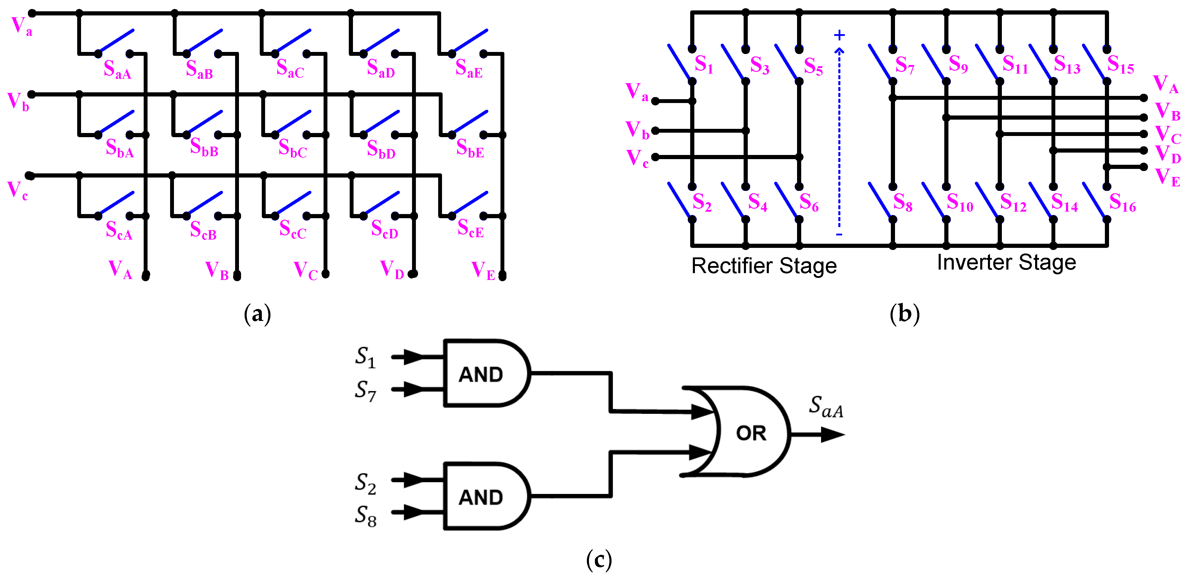
2. Five-Phase Matrix Converter

The five-phase MC comprises of a variety of 15 bidirectional switches. The input and output voltages of the MC can be described as follows:
[ v a v b v c ] = [ V i m   sin ( ω i t ) V i m   sin ( ω i t 2 π 3 ) V i m   sin ( ω i t + 2 π 3 ) ]
[ V A V B V C V D V E ] = [ V o m   sin ( ω o t ) V o m   sin ( ω o t 2 π 5 ) V o m   sin ( ω o t 4 π 5 ) V o m   sin ( ω o t + 4 π 5 ) V o m   sin ( ω o t + 2 π 5 ) ]
where, V i m   and V o m are the amplitude of the input and output voltages, respectively, and ω i   and ω o are the angular frequencies of the input and output voltages, respectively.
The required output voltage from the five-phase MC can be obtained by selecting the appropriate switching state of the matrix switches. The SVM technique is utilized to select the correct state and its on time period. There are two techniques for SVM to control the MC. The first is direct SVM, with the topology shown in Figure 1a, and the second is indirect SVM, which uses the topology shown in Figure 1b. These techniques will be comparatively explained in the following sections.

2.1. Direct SVM for a Five-Phase MC

The fifteen bidirectional switches of the five-phase MC displayed in Figure 1a have 2 15 altered switching states. The number of permissible switching states is reduced to 243 ( 3 5 ) after applying the following conditions: (1) short circuits in the input phases must be avoided, and (2) all output phases must be connected to any input phase at any instant. The instantaneous space vector of the three-phase input and the five-phase output line voltages can be given as follows:
V i = 2 3 ( v a b + a 1 . v b c + a 1 2 . v c a ) = | v i | e j α i
V o = 2 5 ( v A B + a 2 . v B C + a 2 2 . v C D + a 2 3 . v D E + a 2 4 . v E A ) = | v o | e j α o
where, V i   and V o are the space vectors of the input and output voltages, respectively, and α i   and α o are the phase angle of the input and output voltages, respectively, where a 1 = e j 2 π / 3 and a 2 = e j 2 π / 5 .
The permissible switching states can be denoted as {d, s, w}, where the number of output phases connected to input phases a, b and c are signified by d, s and w, respectively. These switching states are analyzed in five groups.
In the first group, the phases of all outputs are linked to the same input phase. There are three possible states, and {d, s, w} can be termed as {5,0,0}, {0,5,0} or {0,0,5}. This group is the zero-vector group, where its vector magnitude and frequency are zero.
The second group can be described by 30 possible switching states. In this group, one output phase is connected to a specified input, and the other four outputs are connected to any other input. {d, s, w} can be termed as {4,0,1}, {4,1,0}, {1,0,4}, {1,4,0} and {0,1,4}. For a specified state, {1,4,0}, (output phase A is connected to input phase a, and output phases B, C, D and E are connected to input phase b), the magnitude of the space vector of the output voltage can be calculated from Equation (4) and will be 0.47 v a b . The phase angle of the space vector of the output voltage will be 54°. This means that the magnitude of the output voltage vector depends on the line input voltage related to the selected state, and its phase angle does not depend on the phase angle of the input voltage. Hence, the vectors of this group have a constant frequency in space, but their magnitudes are variable.
The third group can be defined by 60 possible switching states. In this group, two output phases are connected to a specified input, and the other three outputs are connected to any other input. {d, s, w} can be termed as {0,2,3}, {3,0,2}, {2,0,3}, {0,3,2}, {2,3,0} and {3,2,0}. The vectors of this group also have a constant frequency with a variable magnitude.
The fourth group can be defined by 60 possible switching states. In this group, one output phase is connected to a specified input, one output is connected to a different input and the other three outputs are connected to the third input phase. {d, s, w} can be termed as {1,1,3}, {3,1,1} and {1,3,1}. The vectors of this group have variable frequencies in space and variable magnitudes.
The fifth group can be defined by 90 possible switching states. In this group, one output phase is connected to a specified input, two outputs are connected to a different input and the other two outputs are connected to the third input phase. {d, s, w} can be termed as {2,2,1}, {1,2,2} and {2,1,2}. The vectors of this group have variable frequencies and variable magnitudes.
The large number of possible switching states with variable magnitudes and frequencies makes it difficult to implement the direct modulation technique. The indirect SVM technique was utilized with a three-phase MC in [33,34]. This technique is extended with five-phase MCs and will be discussed in the following sections.

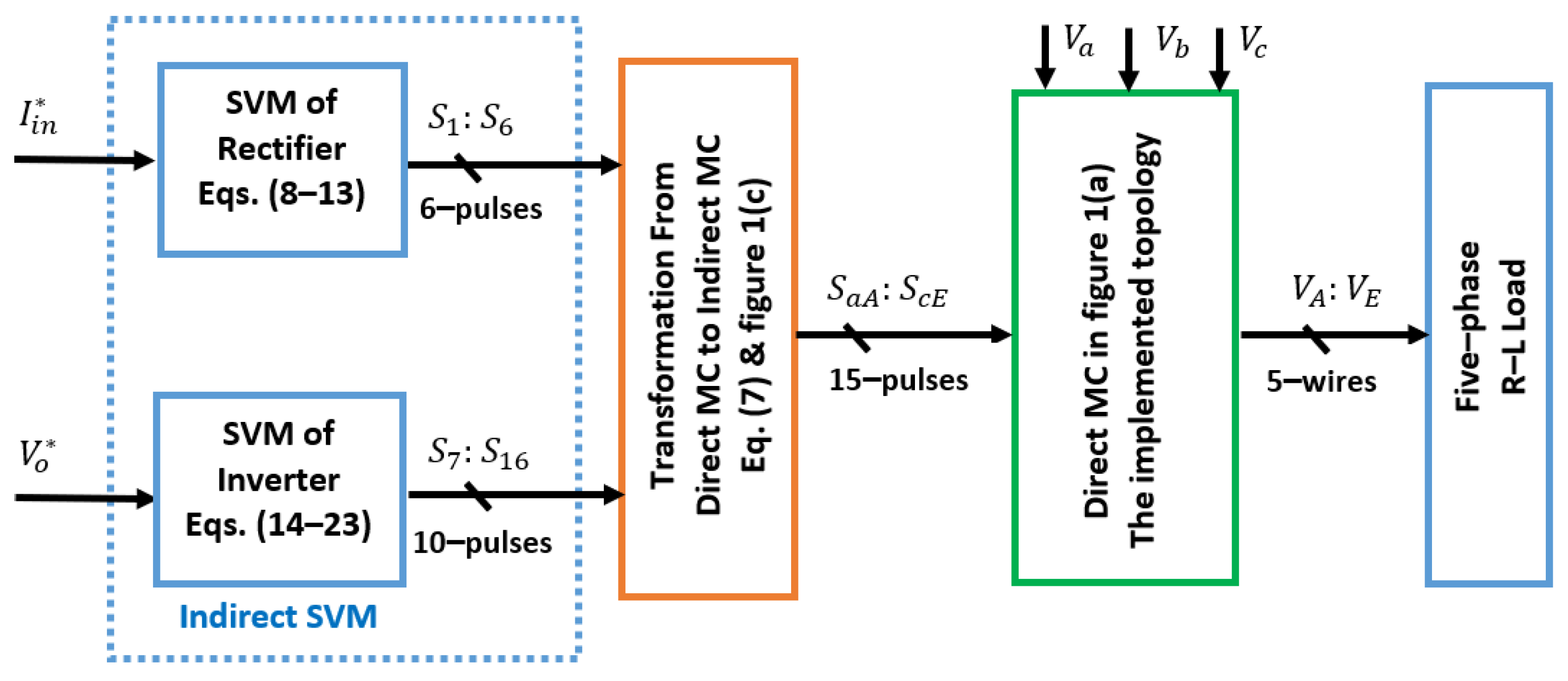
2.2. Indirect SVM for a Five-Phase MC

This technique deals with the five-phase MC as a virtual two-stage converter with a virtual DC link. The first stage is a three-phase current source rectifier, and the second is a five-phase voltage source inverter (VSI), as described in Figure 1b. This technique combines the duty cycles of the rectifier with the duty cycles of the five-phase VSI to produce the duty cycles for the five-phase MC. The transformation from the indirect architecture to the direct one is derived as in Equations (5)–(7), where K is the transfer function of the direct MC, E is the transfer function for the rectifier and N is the transfer function for the five-phase VSI. Figure 1c shows how to obtain the switching control pulse in the direct topology of the switch S a A from the obtained switching control pulses of the indirect topology. This is simply done using AND and OR logic circuits:
[ V A V B V C V D V E ] = [ S a A S b A S c A S a B S b B S c B S a C S b C S c C S a D S b D S c D S a E S b E S c E ] [ v a v b v c ]
K = NE
[ S a A S b A S c A S a B S b B S c B S a C S b C S c C S a D S b D S c D S a E S b E S c E ] = [ S 7 S 8 S 9 S 10 S 11 S 12 S 13 S 14 S 15 S 16 ] [ S 1 S 3 S 5 S 2 S 4 S 6 ]

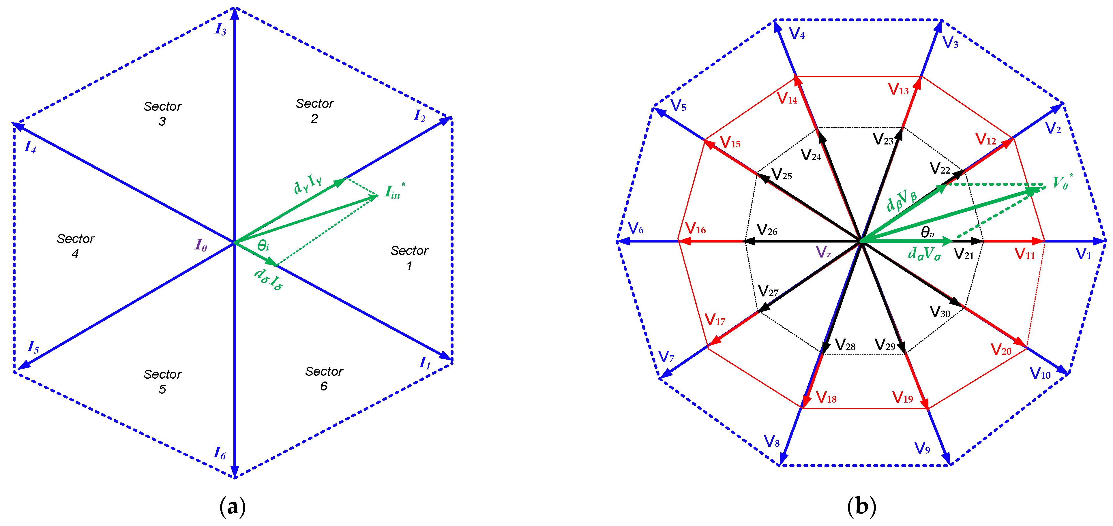
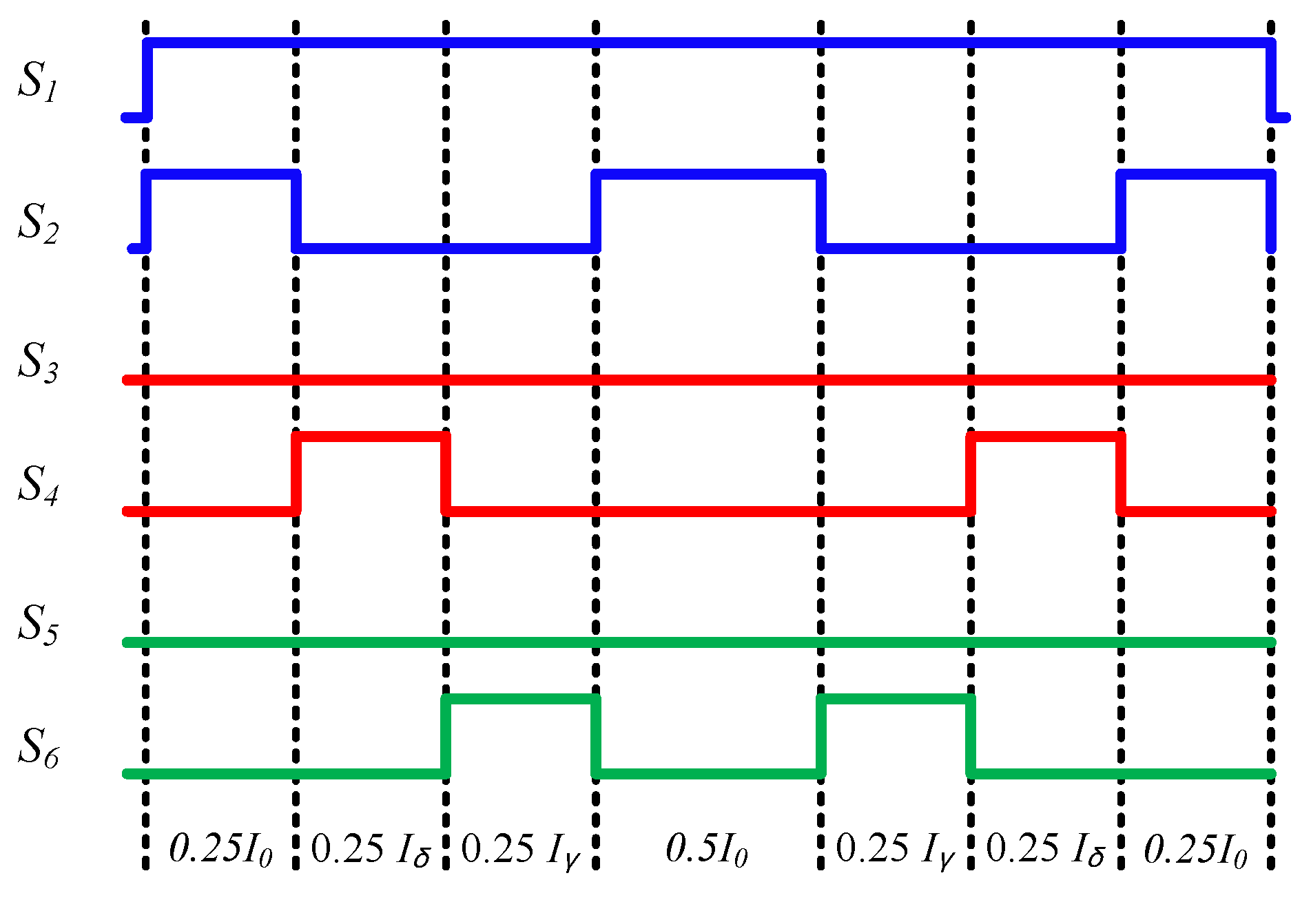
2.2.1. Three-Phase Rectifier Stage

The six switches for the three-phase rectifier have nine permissible switching states: three zero vectors ( I 7 I 9 ) and six active vectors ( I 1 I 6 ). These switching states can be defined in the hexagon shown in Figure 2a, which is divided into six sectors. The reference vector for the input current ( I i n * ) can be composed using the adjacent vector ( I γ , I δ   and   I 0 ) as in Equation (8). The duty cycles for both the active and zero vectors are calculated as in Equations (9)–(11) [35]:
I i n * = d γ I γ + d δ I δ + d o c I 0
d δ = m i sin ( π 3 θ i )
d γ = m i sin ( θ i )
d 0 c = 1 d γ d δ
where,   m i denotes the modulation index for the input current with a range of 0:1 and θ i is the angle between the reference input current vector and the first vector in the sector in which the reference is located. The DC link power equals the input power, as there is no reactive element.
The DC link voltage average value can be obtained from the power balance between the input side and the DC link point as follows:
V D C = 3 2 V i n m i cos i n
where V i n is the input phase voltage peak value and i n is the displacement angle between the input phase current and the input AC phase voltage.
The symmetric sequence arrangements for a three-phase rectifier that minimize the number of switching is arranged as in Equation (13). Table 1 shows the switching vectors, which minimize switching losses at different sectors. In Table 1, the switching state I1 (a, b) means that the rectifier switches S1 and S4 are on while switches S2, S3, S5 and S6 are off. The switching pattern for the rectifier switches for the first sector is illustrated in Figure 3. It can be noted that the state of the three switches of the rectifier remain fixed for the whole switching process for each sector. In addition, the states of only two switches are changed between two adjacent switching states, as described in Figure 3. In the first sector, S1 is on and S3 and S5 are off for the whole switching period:
  d 0 c 4 ,   d δ 2 ,   d γ 2 ,   d 0 c 2 ,   d γ 2 ,   d δ 2 ,   d 0 c 4

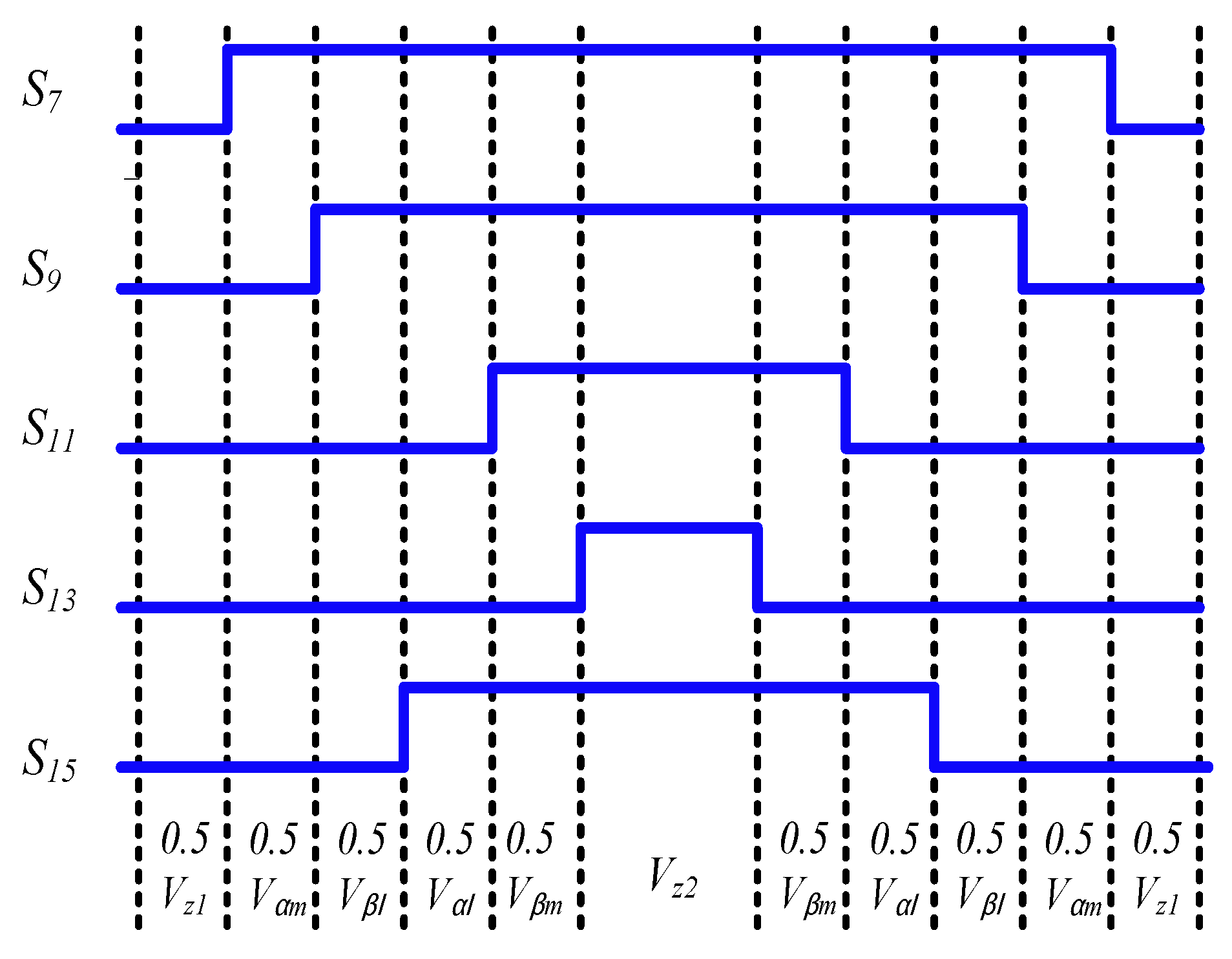
2.2.2. Five-Phase Inverter Stage

The ten switches of the five-phase VSI have thirty-two permissible switching states: two zero vectors V 0 and thirty active vectors ( V 1 V 30 ). These switching states can be defined in the decagon shown in Figure 2b, which is divided into ten sectors. The active vectors for the voltage can be divided into three levels: small vectors with a magnitude of 0.2472 V D C , medium vectors with a magnitude of 0.4 V D C and large vectors with a magnitude of 0.6472 V D C [30]. The reference vector for the output voltage ( V o * ) can be composed using the adjacent vector ( V α   , V β   ,   V z ), as given by Equation (14). The duty cycles for both the active and zero vectors are calculated as in Equations (15)–(17). The maximum value for the reference vector of the output voltage is limited to 0.6155 V D C :
V O * = d α V α + d β V β + d z V z
d α = m v . sin ( π 5 θ v )
d β = m v . sin ( θ v )
d z = 1 d α d β
where,   m v denotes the required value for the modulation index for the output voltage and θ v is the angle between the reference output voltage vector and the first vector in the sector in which the reference is located [17]. The number of switching events can be minimized by using only medium and large vectors with SVM. The duty cycles of the medium and large vectors are calculated according to their lengths relative to each other as follows:
d α l = d α V l V l + V m
d α m = d α V m V l + V m
d β l = d β V l V l + V m
d β l = d β V m V l + V m
The time of the medium vector is 38.2% of the entire active time, and the time for the large vector is 61.8% of the entire active time. Due to this subdivision, the maximum value for the reference vector of the output voltage is limited to a value of 0.5257 V D C [17].
The symmetric sequence arrangements for a five-phase VSI which minimizes the number of switching is arranged as in Equation (22). The switching vectors which minimize switching losses at different sectors are described in Table 2. In Table 2, the switching state V11 (10000) means that the inverter switches S7, S10, S12, S14 and S16 are on while switches S8, S9, S11, S13 and S15 are off. The switching pattern for the upper switches of the five-phase VSI for the first sector is illustrated in Figure 4. It can be noted that the state of only one switch of the upper switches will be changed between two adjacent switching states:
d z 1 2 ,   d α m 2 ,   d β l 2 ,   d α l 2 ,   d β m 2 ,   d z 2 1 ,   d β m 2 ,   d α l 2 ,   d β l 2 ,   d α m 2 ,   d z 1 2
d z 1 =   d z 2 =   d z 2

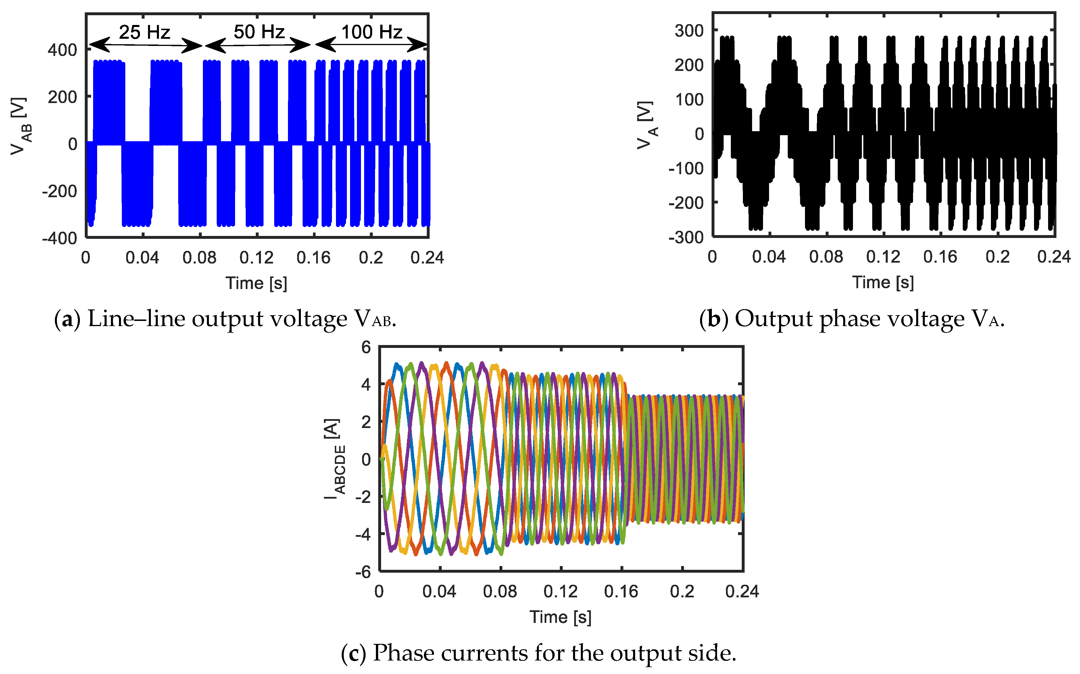
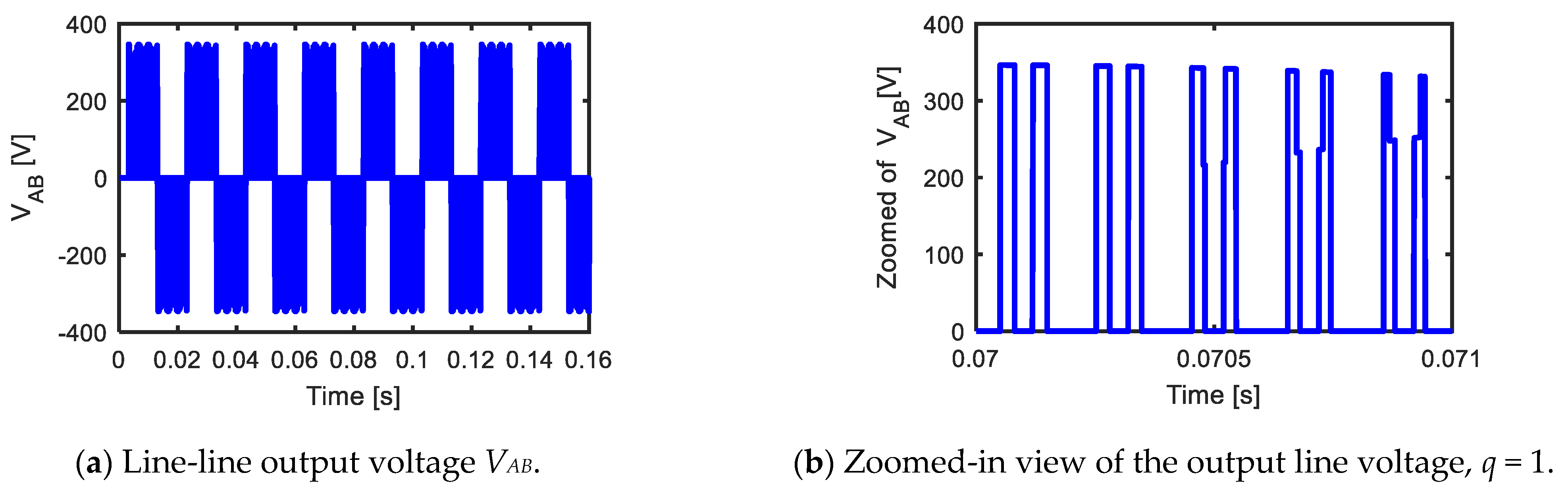
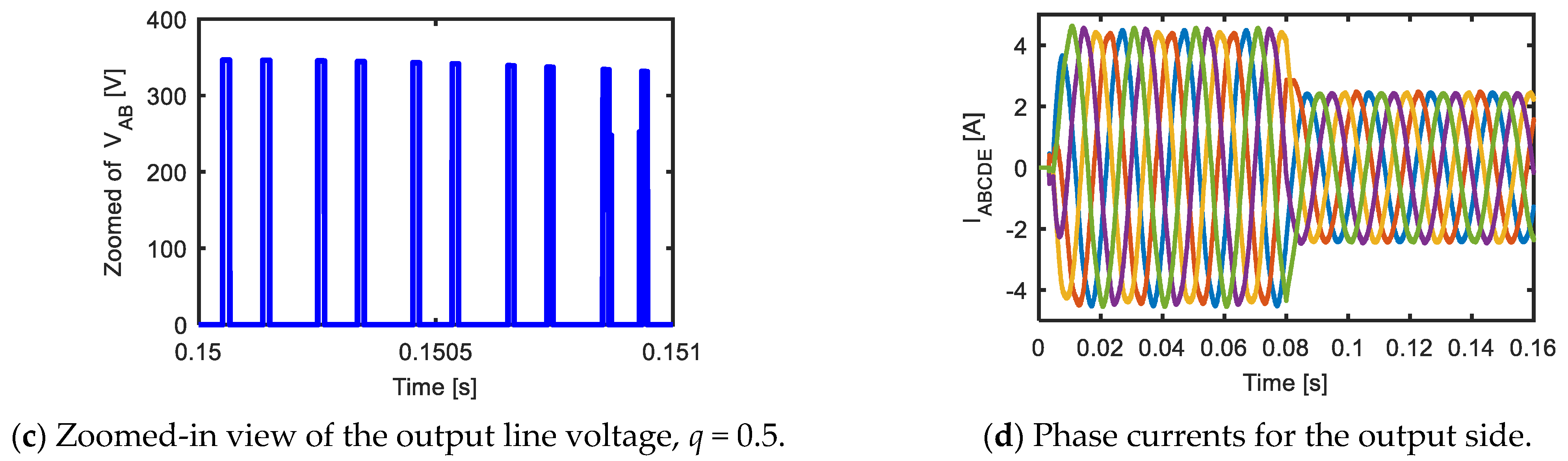
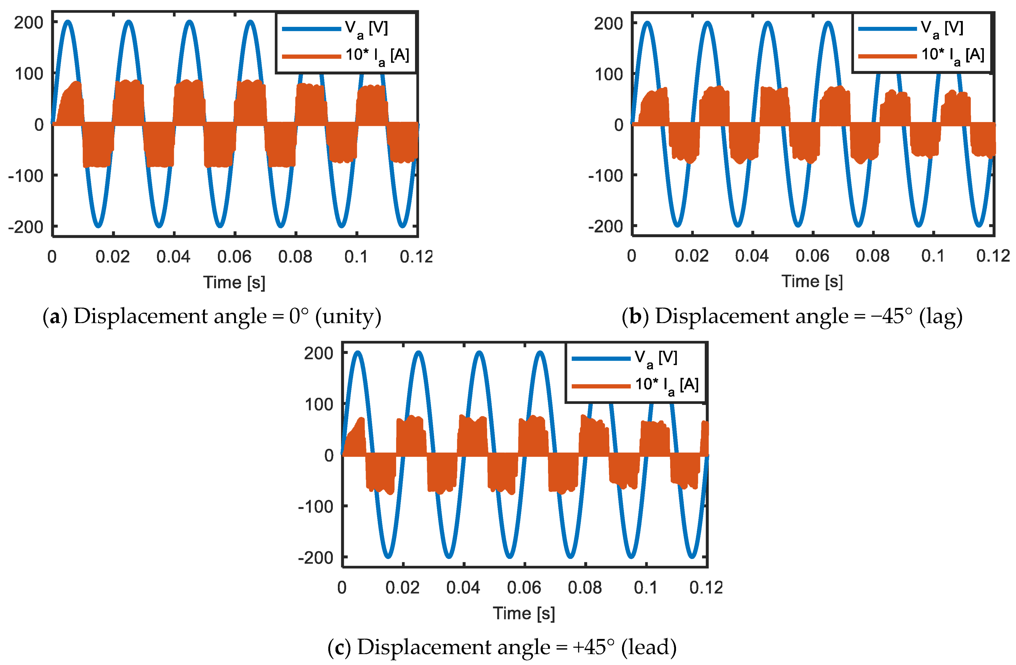
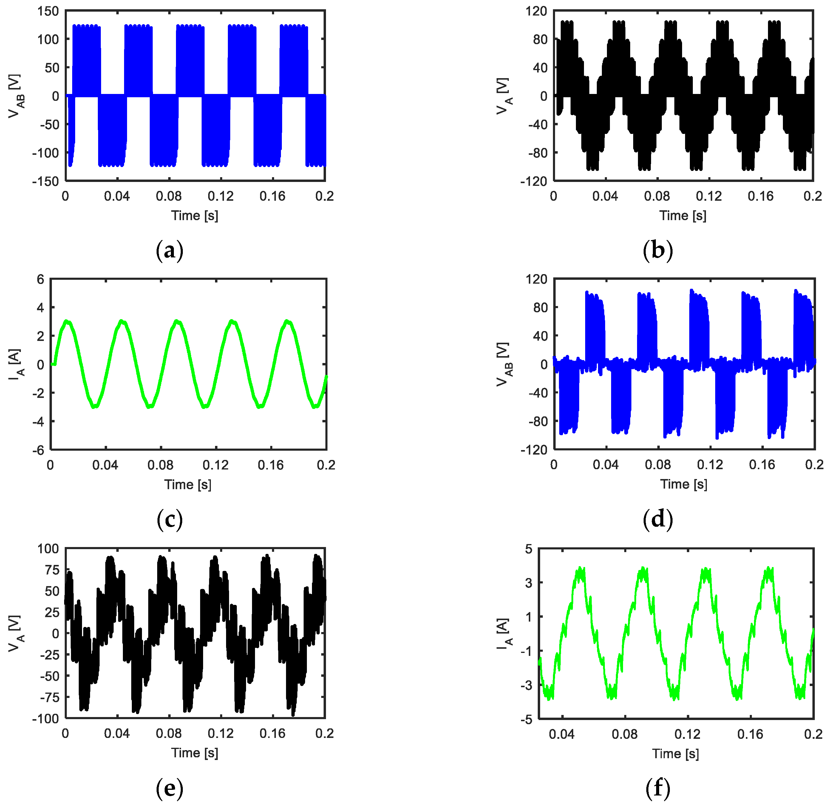
3. Performance Analysis of the Five-Phase MC

This section studies the performance of a static load application for a five-phase MC. The output side of the five-phase MC was connected to a passive R-L load with a value of R = 20 Ω and L = 40 mH. The input side of the five-phase MC was connected to three-phase supply of 200 V and 50 Hz. Indirect SVM was applied with a switching frequency of 5 kHz and a sampling time of 2 μ s to control the matrix switches. The direct topology, shown in Figure 1a, was implemented, and the previously analyzed equations were used to transform and obtain the required switching control pulses. This is simply described in the block diagram shown in Figure 5.
Figure 6 illustrates the simulation results for the transient performance of the five-phase MC with a static load with different output frequencies (25, 50 and 100 Hz). Figure 6a shows the simulation results for the output line voltages V A B . The output frequency changed from 25 Hz to 50 Hz at t = 0.08 s, then to 100 Hz at t = 0.16 s. Figure 6b shows the output phase voltage VA from the five-phase MC. The output phase currents have been described in Figure 6c. It was found from Figure 6 that the five-phase MC had the ability to give a wide range of output frequencies with good transient performance.
The property of the MC to control the voltage magnitude has been shown in Figure 7. The reference value of the output voltage was changed to half of its initial value (from 180 V to 90 V) at t = 0.08 s. Figure 7a shows the output line voltage VAB with magnitude control. Figure 7b, c shows a zoomed-in view of the output line voltage before and after t = 0.08 s, respectively. It was noticed that the pulse width of the output line voltage was reduced to half its initial value after t = 0.08 s. In addition, the voltage magnitude control can be noticed from the output phase currents in Figure 7d. The output phase currents were decreased to half of their initial values after t = 0.08 s.
In Figure 8, a five-phase MC was used to control the displacement factor for the input side, where Figure 8a shows a unity value for the displacement factor and Figure 8b shows that the displacement factor with current lags the voltage by a displacement angle of 45°. Figure 8c shows the displacement factor with current leads the voltage by a displacement angle of 45°.

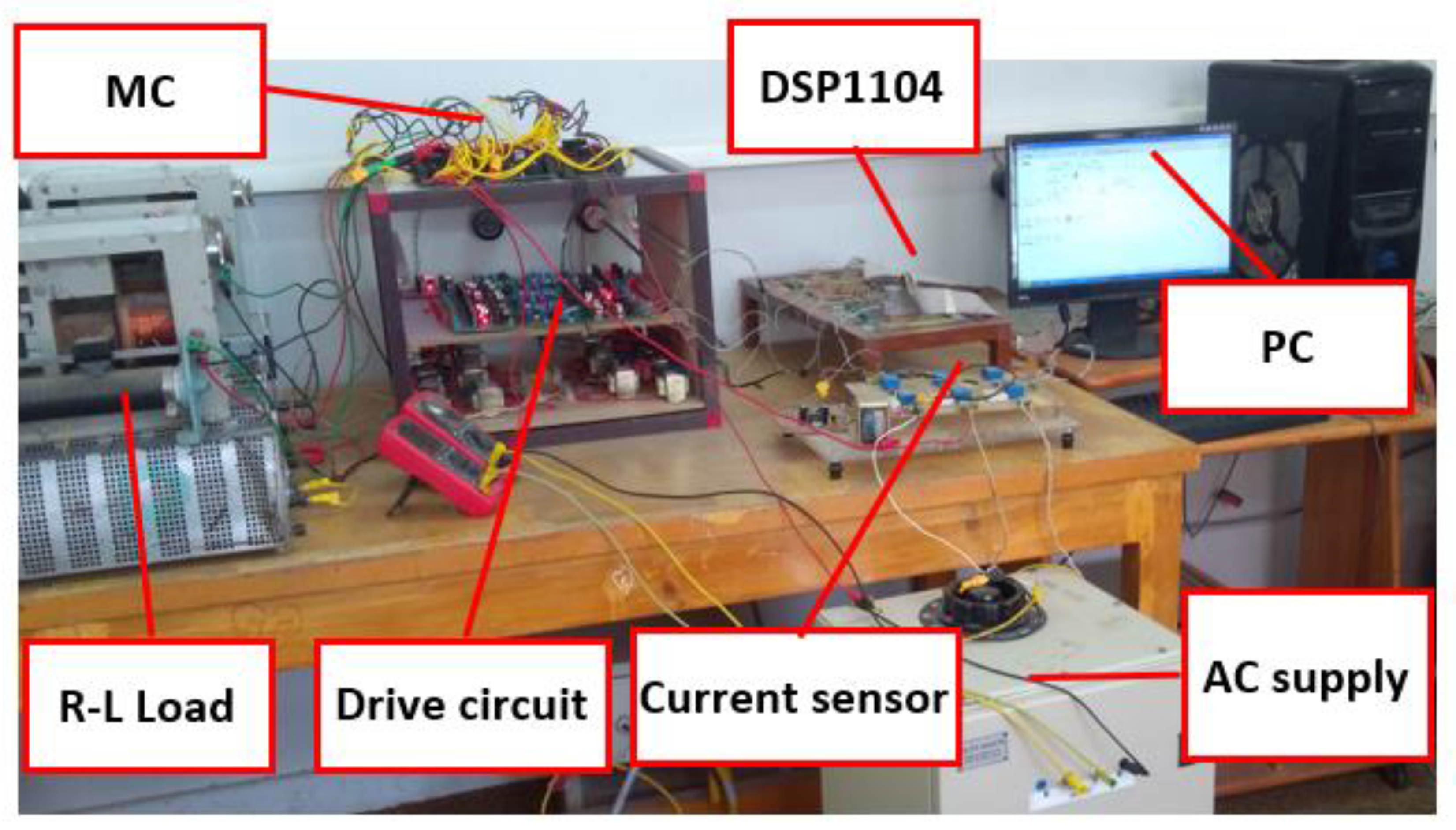
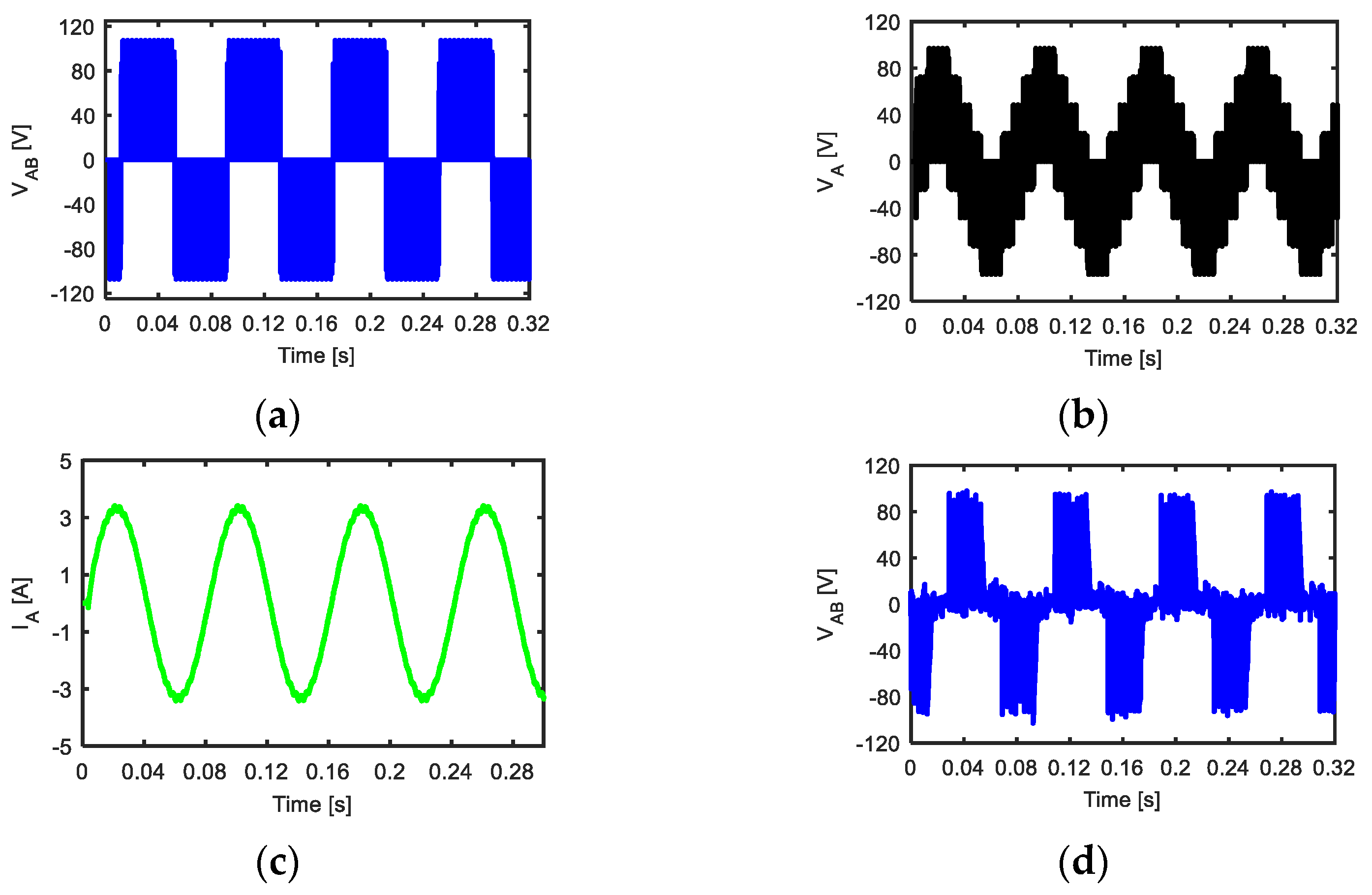
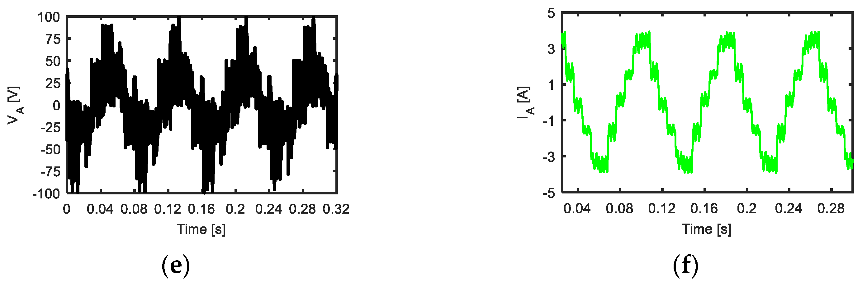
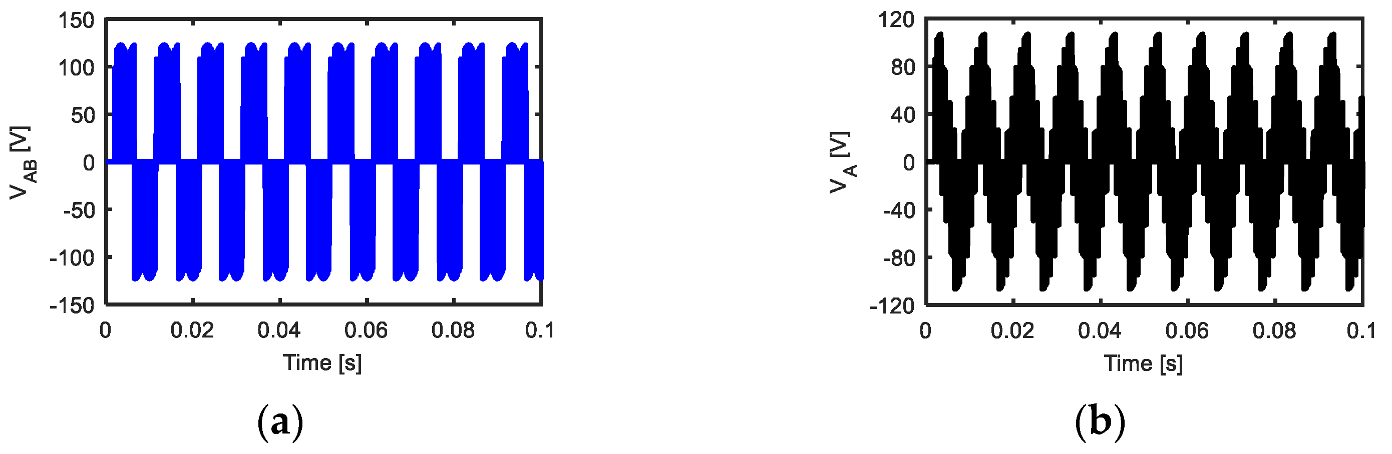
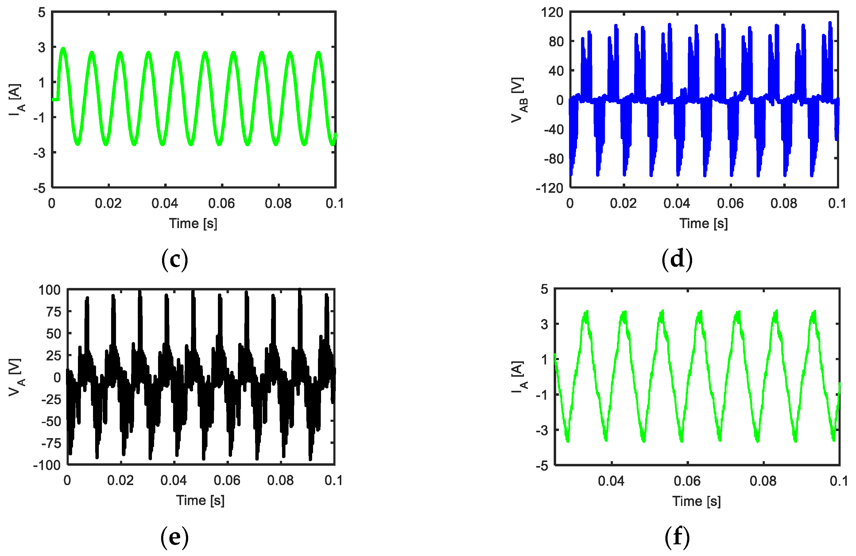
4. Experimental Results

The experimental test bench shown in Figure 9 was utilized to validate the simulation results presented before. It consisted of a three- to five-phase MC (direct topology) based on metal–oxide–semiconductor field-effect transistor(MOSFET) switches (20 A) and connected to a static R-L load (R = 20 Ω, L = 40 mH). The input side of the MC was connected to a three-phase supply with a line voltage of 100 V and frequency of 50 Hz. Indirect SVM was applied with a switching frequency of 5 kHz and a sampling time of 200 μ s to control the switches of the direct MC. The current and voltage modulation indexes ( m i and m v ) were 1 and 0.8, respectively. The control signals of the MC switches were realized through a DSP1104. The system was implemented at different reference output frequencies to validate the advantage of the MC. Figure 10, Figure 11 and Figure 12 compare the simulated and measured results at different reference output frequencies (12.5 Hz, 25 Hz and 100 Hz) for the output line and phase voltages and the output phase current. From these figures, an acceptable agreement between the simulated and measured results was noticed. In addition, these figures prove the ability of the MC to give a wide range of output frequencies which can be equal, lower than or greater than the frequency of the input voltage. In addition, the absence of the massive DC link capacitors was an essential feature for the MC, resulting in an increased reliability and a reduced size converter. Hence, motor drive systems based on the MC could be a suitable solution for high-speed applications which require high reliability and high operating output frequencies, such as aerospace applications, military applications and hospital pumping.

5. Conclusions

In this paper, a mathematical model of the five-phase matrix converter (MC) was introduced. In addition, a comparison between the direct and the indirect space vector modulation methods (SVMs) was presented. Furthermore, the mathematical transformation between the direct and the indirect topology of the MC was constructed. The symmetric sequence switching technique was applied with the indirect technique to minimize the switching losses. Moreover, the mathematical model of the five-phase MC was validated using a static R-L load. The validated mathematical model of the MC has proven that the direct topology of the MC can be simply applied and controlled using indirect SVM. The performance of the MC was studied and analyzed under steady state and transient conditions. The ability of the five-phase MC to obtain a controllable input displacement factor, voltage magnitude control and wide range for the output frequency was shown. A comparison between the simulated and measured results was reported at different reference output frequencies. Good agreement between the simulation and experimental results has been noticed. In addition to the main advantage of the absence of the DC link capacitors, the MC could provide a higher output frequency than the input one. These advantages make the MC more reliable and a suitable solution for high-speed applications, such as aerospace applications, military applications and hospital pumping.

Author Contributions

Conceptualization, K.B.T., M.N.I. and H.R.; validation, K.B.T., M.N.I. and H.R.; writing—original draft preparation, K.B.T.; writing—review and editing, M.N.I., H.R., E.E.E.-k. and P.S. All authors have read and agreed to the published version of the manuscript.

Funding

The authors acknowledge the Special Research Fund of Ghent University (BOF) for the financial support during this work.

Conflicts of Interest

The authors declare no conflict of interest.

References

  1. Atallah, K.; Wang, J.B.; Howe, D. Torque-ripple minimization in modular permanent-magnet brushless machines. IEEE Trans. Ind. Appl. 2003, 39, 1689–1695. [Google Scholar] [CrossRef]
  2. Wang, J.B.; Atallah, K.; Howe, D. Optimal torque control of fault tolerant permanent magnet brushless machines. IEEE Trans. Magn. 2003, 39, 2962–2974. [Google Scholar] [CrossRef]
  3. Tawfiq, K.B.; Ibrahim, M.N.; El-Kholy, E.E.; Sergeant, P. Refurbishing three-phase synchronous reluctance machines to multiphase machine. Electr. Eng. 2020. [Google Scholar] [CrossRef]
  4. Levi, E. Advances in converter control and innovative exploitation of additional degrees of freedom for multiphase machines. IEEE Trans. Ind. Electron. 2016, 63, 433–448. [Google Scholar] [CrossRef] [Green Version]
  5. Prieto, G.; Duran, M.; Aciego, J.; Martin, C.; Barrero, F. Model predictive control of six-phase induction motor drives using virtual voltage vectors. IEEE Trans. Ind. Electron. 2018, 65, 27–37. [Google Scholar] [CrossRef]
  6. Duran, M.J.; Barrero, F. Recent advances in the design, modeling and control of multiphase machines—Part II. IEEE Trans. Ind. Electron. 2016, 63, 459–468. [Google Scholar] [CrossRef]
  7. Tawfiq, K.B.; Ibrahim, M.N.; El-Kholy, E.E.; Sergeant, P. Performance Improvement of Existing Three phase Synchronous Reluctance Machine: Stator Upgrading to 5-phase with Combined Star-Pentagon Winding. IEEE Access 2020, 8, 143569–143583. [Google Scholar] [CrossRef]
  8. Armin, M.; Roy, P.N.; Sarkar, S.K.; Das, S.K. LMI-based robust PID controller design for voltage control of islanded micro grid. Asian J. Control 2018, 20, 2014–2025. [Google Scholar] [CrossRef]
  9. Ibrahim, M.N.; Tawfiq, K.B.; Rashad, E.M.; Sergeant, P. Synchronous Reluctance Machines: Performance Evaluation with and Without Ferrite Magnets. In Proceedings of the International Conference on Industrial Manufacturing and Metallurgy (ICIM 2020), Nizhny Tagil, Russia, 18–19 June 2020. [Google Scholar]
  10. Zhang, J.; Dan, H.; Empringham, L.; De Lillo, L.; Wheeler, P. Matrix Converter Open-Circuit Fault Behavior Analysis and Diagnosis with a Model Predictive Control Strategy. IEEE J. Emerg. Sel. Top. Power Electron. 2018, 6, 1831–1839. [Google Scholar] [CrossRef]
  11. Levi, E. Multi-phase electric machines for variable speed applications. IEEE Trans. Ind. Electron. 2008, 55, 1893–1909. [Google Scholar] [CrossRef]
  12. Huber, L.; Borojevic, D. Space vector modulator for forced commutated cycloconverters. In Proceedings of the Conference Record of the IEEE Industry Applications Society Annual Meeting, San Diego, CA, USA, 1–5 October 1989; pp. 871–876. [Google Scholar]
  13. Xu, H.; Toliyat, H.A.; Petersen, L.J. Five-phase induction motor drives with DSP based control system. IEEE Trans. Power Electron. 2002, 17, 524–533. [Google Scholar]
  14. Levi, E.; Bojoi, R.; Farina, F.; Toliyat, H.A.; Williamson, S. Multi-phase induction motor drives-A technology status review. IET Electr. Power Appl. 2007, 1, 489–516. [Google Scholar] [CrossRef] [Green Version]
  15. Tawfiq, K.B.; Abdou, A.F.; El-Kholy, E.E.; Shokralla, S.S. A modified space vector modulation algorithm for a matrix converter with lower total harmonic distortion. In Proceedings of the 2016 IEEE 59th International Midwest Symposium on Circuits and Systems (MWSCAS), Abu Dhabi, UAE, 16–19 October 2016; pp. 1–4. [Google Scholar]
  16. Tawfiq, K.B.; Abdou, A.F.; El-Kholy, E.E.; Shokralla, S.S. Application of matrix converter connected to wind energy system. In Proceedings of the 2016 Eighteenth International Middle East Power Systems Conference (MEPCON), Cairo, Egypt, 27–29 December 2016; pp. 604–609. [Google Scholar]
  17. Dabour, S.M.; Hassan, A.E.; Rashad, E. Analysis and implementation of space vector modulated five-phase matrix converter. Int. J. Electr. Power Energy Syst. 2014, 63, 740–746. [Google Scholar] [CrossRef]
  18. Gyugyi, L.; Pelly, B.R. Static Power Frequency Changers-Theory, Performance and Application; J. Wiley: New York, NY, USA, 1976. [Google Scholar]
  19. Venturini, M. A new sine wave in sine wave out conversion technique which eliminates reactive elements. Proc. POWERCON 1980, 7, E3.1–E3.15. [Google Scholar]
  20. Alesiana, A.; Venturini, M. Analysis and design of optimum-amplitude nine switch direct AC–AC converters. IEEE Trans. Power Electron. 1989, 4, 101–112. [Google Scholar] [CrossRef]
  21. Casadei, D.; Grandi, G.; Serra, G.; Tani, A. Space vector control of matrix converters with unity power factor and sinusoidal input/output waveforms. Proc. EPE Conf. 1993, 7, 170–175. [Google Scholar]
  22. Leon, J.I.; Lopez, O.; Franquelo, L.G.; Doval-Gandoy, J.; Vazquez, S.; Alvarez, J.; Freijedo, F.D. Multilevel multiphase feed-forward space vector modulation technique. IEEE Trans. Ind. Electron. 2010, 57, 2066–2075. [Google Scholar] [CrossRef]
  23. Huber, L.; Borojevic, D. Space vector modulated three-phase to three-phase matrix converter with input power factor correction. IEEE Trans. Ind. Appl. 1995, 31, 1234–1246. [Google Scholar] [CrossRef]
  24. Ahmed, S.M.; Iqbal, A.; Abu-Rub, H.; Khan, M.R. Space vector PWM technique for a novel 3 to 5 phase matrix converter. In Proceedings of the 2010 IEEE Energy Conversion Congress and Exposition, Atalanta, GA, USA, 12–16 September 2010; pp. 1875–1880. [Google Scholar]
  25. Yoon, Y.-D.; Sul, S.-K. Carrier-based modulation technique for matrix converter. IEEE Trans. Power Electron. 2006, 21, 1691–1703. [Google Scholar] [CrossRef]
  26. Bhowmick, S.; Umana, L. Design and Analysis of the Low Device Stress Active Power Decoupling for Single-Phase Grid Connection for a Wide Range of Power Factor. IEEE J. Emerg. Sel. Topic Power Electron. 2018, 6, 1921–1931. [Google Scholar] [CrossRef]
  27. Wang, B.; Shen, Z.; Liu, H.; Hu, J. Linear ADRC direct current control of grid-connected inverter with LCL filter for both active damping and grid voltage induced current distortion suppression. IET Power Electron. 2018, 11, 1748–1755. [Google Scholar] [CrossRef]
  28. Amin, A.; Tawfiq, K.B.; Youssef, H.; El-Kholy, E.E. Performance analysis of inverter fed from wind energy system. In Proceedings of the 2016 Eighteenth International Middle East Power Systems Conference (MEPCON), Cairo, Egypt, 27–29 December 2016; pp. 512–516. [Google Scholar]
  29. Wang, H.; Zhang, Y.; Mei, S.; Sun, Y.; Li, X.; Zhang, G. Control method for the two-stage matrix converter to enhance the linear voltage transfer ratio. IET Power Electron. 2018, 11, 2295–2301. [Google Scholar] [CrossRef]
  30. Ahmed, S.M.; Iqbal, A.; Abu-Rub, H. Carrier-based PWM technique of a novel three-to-seven-phase matrix converter. In Proceedings of the Presented at the International Conference on Electrical Machines ICEM, Rome, Italy, 3–6 September 2010. [Google Scholar]
  31. Tawfiq, K.B.; Mansour, A.; Ibrahim, M.N.F.; Elkholy, E.; Sergeant, P. Implementation of matrix converter in wind energy conversion system with modified control techniques. Electr. Power Compon. Syst. 2019, 47, 1316–1331. [Google Scholar] [CrossRef]
  32. Ahmed, S.M.; Iqbal, A.; Abu-Rub, H. Generalized Duty-Ratio-Based Pulse width Modulation Technique for a Three-to- kk Phase Matrix Converter. IEEE Trans. Ind. Electron. 2011, 58, 3925–3937. [Google Scholar] [CrossRef]
  33. Iqbal, A.; Ahmed, M.; Abu-Rub, H. Space vector PWM technique for a three-to-five-phase matrix converter. IEEE Trans. Ind. Appl. 2012, 48, 489–497. [Google Scholar] [CrossRef]
  34. Simon, O.; Mahlein, J.; Muenzer, M.N.; Bruckmann, M. Modern solution for industrial matrix converter applications. IEEE Trans. Ind. Electron. 2002, 49, 401–406. [Google Scholar] [CrossRef]
  35. Ahmed, S.M.; Iqbal, A.; Abu-Rub, H.; Rodriguez, J.; Rojas, C. Simple carrier-based PWM technique for a three to nine phase matrix converter. IEEE Trans. Ind. Electron. 2011, 58, 5014–5023. [Google Scholar] [CrossRef]
Figure 1. (a) Direct five-phase matrix converter (MC), (b) indirect five-phase MC and (c) transformation from an indirect to direct topology for switch S a A .
Mathematics 09 00096 g001
Figure 2. (a) Hexagon of the rectifier and (b) decagon of the inverter.
Mathematics 09 00096 g002
Figure 3. Switching sequence for the rectifier in the first sector.
Mathematics 09 00096 g003
Figure 4. Switching sequence for a five-phase voltage source inverter (VSI) in the first sector.
Mathematics 09 00096 g004
Figure 5. Block diagram for the implementation of the direct topology.
Mathematics 09 00096 g005
Figure 6. Simulation results for a static R-L load with output frequencies of 25, 50 and 100 Hz.
Mathematics 09 00096 g006
Figure 7. Simulation results for control of the magnitude of the output voltage and the 50 Hz output frequency.
Mathematics 09 00096 g007aMathematics 09 00096 g007b
Figure 8. Simulation results for control of the input displacement factor.
Mathematics 09 00096 g008
Figure 9. The complete experimental setup.
Mathematics 09 00096 g009
Figure 10. (ac) Simulated and (df) measured results for a 12.5 Hz output frequency, (a,d) line voltage VAB, (b,e) phase voltage VA and (c,f) output phase current I.
Mathematics 09 00096 g010aMathematics 09 00096 g010b
Figure 11. (ac) Simulated and (df) measured results for a 25 Hz output frequency, (a,d) line voltage VAB, (b,e) phase voltage VA and (c,f) output phase current IA.
Mathematics 09 00096 g011
Figure 12. (ac) Simulated and (df) measured results for a 100 Hz output frequency, (a,d) line voltage VAB, (b,e) phase voltage VA and (c,f) output phase current IA.
Mathematics 09 00096 g012aMathematics 09 00096 g012b
Table 1. Switching sequence for the rectifier for different sectors to minimize switching losses.
Sector No.IδIγI0
1I1 (a, b)I2 (a, c)I7 (a, a)
2I2 (a, c)I3 (b, c)I9 (c, c)
3I3 (b, c)I4 (b, a)I8 (b, b)
4I4 (b, a)I5 (c, a)I7 (a, a)
5I5 (c, a)I6 (c, b)I9 (c, c)
6I6 (c, b)I1 (a, b)I8 (b, b)
Table 2. Switching vectors for the inverter at different sectors to minimize switching losses.
Sector No. V α m V α l V β m V β l V z 1 V z 2
1V11 (10000)V1 (11001)V12 (11101)V2 (11000)V31 (00000)V32 (11111)
2V13 (01000)V2 (11000)V3 (11100)V12 (11101)
3V13 (01000)V4 (01100)V3 (11100)V14 (11110)
4V15 (00100)V4 (01100)V5 (01110)V14 (11110)
5V15 (00100)V6 (00110)V5 (01110)V16 (01111)
6V17 (00010)V6 (00110)V7 (00111)V16 (01111)
7V17 (00010)V8 (00011)V7 (00111)V18 (10111)
8V19 (00001)V8 (00011)V9 (10011)V18 (10111)
9V19 (00001)V10 (10001)V9 (10011)V20 (11011)
10V11 (10000)V10 (10001)V1 (11001)V20 (11011)
Publisher’s Note: MDPI stays neutral with regard to jurisdictional claims in published maps and institutional affiliations.

