
Diffusion Model of Parallel Plate Crack Grouting Based on Foaming Expansion Characteristics of Polymer Slurry


1
School of Water Conservancy Science and Engineering, Zhengzhou University, Zhengzhou 450001, China
2
School of Civil Engineering, Guangxi University, Nanning 530004, China
*
Authors to whom correspondence should be addressed.
Mathematics 2021, 9(22), 2907; https://0-doi-org.brum.beds.ac.uk/10.3390/math9222907
Submission received: 10 October 2021
/
Revised: 8 November 2021
/
Accepted: 14 November 2021
/
Published: 15 November 2021
(This article belongs to the Special Issue Analytical, Numerical and Big-Data-Based Methods in Deep Rock Mechanics)
Abstract
:Polymers as a new chemical grouting material have been widely used in fractured rock mass; however, the understanding of polymer diffusion characteristics still needs to be further improved. In order to study the diffusion mechanism of foamed polymer slurry in rock fissures, the radial diffusion model of polymer single crack grouting is derived in consideration of the factors such as grouting volume, crack width and expansion rate. The influence of different factors on slurry diffusion radius, diffusion pressure and flow rate is analyzed, The diffusion model is verified by finite element numerical simulation. The findings show that (1) The results of slurry diffusion radius, pressure and velocity distribution at different times under different working conditions in the present model are in good agreement with the analytical solution; (2) The diffusion pressure is directly proportional to the grouting volume and expansion multiple, and inversely proportional to the crack width. In addition, diffusion pressure decreases with the increase of diffusion distance, and the pressure at the corresponding distance increases slowly with time, and finally tends to be stable; (3) For the same section, the radial velocity decreases slowly with the increase of time; for different sections, the flow velocity increases sharply with the increase of the distance between the section and the central axis of the grouting hole.
1. Introduction
In underground construction, grouting is one of the effective technical means to improve rock mechanical properties and block groundwater [1,2,3,4,5,6]. Grouting refers to injecting the slurry with cementitious capacity into the cracks, voids or cavities in the rock layer (or soil layer) through grouting drilling holes or grouting pipes, which can drive away the water and air in the cracks, voids or cavities, cement the original loose soil particles or cracks into a whole, and form a “stone body” with new structure, high strength and strong waterproof and impermeability, so as to improve the performance of the rock (soil) layer [7]. In recent years, many new grouting materials and equipment have been come into use, which greatly improves the effectiveness of grouting plugging. With the advantages of safety and environmental protection, fast response, high expansion rate, impermeability and durability, polymer materials have become grouting materials with excellent comprehensive performance [8], and are widely used in foundation reinforcement, dam seepage prevention, road maintenance, etc.
The diffusion mechanism of slurry in rock and soil fractures has always been the focus of research. Many scholars have studied the migration law of slurry in fractured rock mass. Generally, the fractured rock mass is simplified as a parallel plate model [9,10,11,12]. According to different slurry constitutive equations, the diffusion of slurry in rock fractures is studied by the analytical method, and the slurry flow and pressure distribution equations are established to explore the flow law of slurry in fractured rock mass. Some scholars regard the slurry as Newtonian fluid and deduce the fracture grouting diffusion model. For instance, Zhang et al. [13] established a two-dimensional slurry flow model in fractures considering fracture roughness and groundwater viscous resistance, and Li et al. [14] deduced an ideal self-expanding slurry single fracture diffusion model; Furthermore, other scholars regard the slurry as Bingham fluid and deduce the crack grouting diffusion model. For example, Gustafson et al. [15] proposed the analytical model for calculating the penetration length of silica sol grouting. Liu et al. [16] proposed the grouting numerical model of water-rich broken sandstone for ordinary portland cement 42.5 (PO. 42.5), aluminum sulfate cement 42.5 (sac. 42.5) and self-developed cement-based composite grouting material (CGM). And a crack grouting diffusion model considering the time-varying viscosity of cement slurry has been proposed [17].
In the diffusion of one-dimensional flow model, Amadei and Savage [18] proposed a one-dimensional flow model of Bingham slurry in the channel between parallel walls, and analyzed the influence of pressure gradients on slurry flow characteristics; Luo et al. [19] deduced the flow equation of Bingham slurry in one-dimensional inclined single fracture, and analyzed the effects of fracture inclination, viscosity and other factors on the velocity of slurry. In the two-dimensional radial diffusion model, Tani et al. [9] studied the radial diffusion law of cement slurry diffusing in the cracks between parallel plates; while Zhan et al. [20,21] established a hydrodynamic grouting diffusion model of single fracture and analyzed the influence of water flow velocity on the slurry diffusion range. Zhang et al. [22] proposed a theoretical model of horizontal fracture grouting diffusion considering the temporal and spatial variation of slurry viscosity under the condition of a constant grouting rate.
In general, great progress has been made in the research on crack grouting mechanism at home and abroad; however, the existing models take constant density slurry such as sodium silicate, cement slurry and ordinary chemical slurry as the objects, and there is no research on the crack grouting diffusion model of foamed polymer slurry. Two component foamed polyurethane generally has faster reaction speeds and larger expansion rates. According to the added foaming dose, it can expand 10–30 times in 6–30 s [8]. Due to the expansibility of polymer slurry and the void structure characteristics of injected medium, the diffusion characteristics of polymers are more complex, which also brings great difficulties to the selection of polymer grouting parameters in engineering practice [23].
In this paper, based on the foaming expansion characteristics of polymer slurry and the theory of viscous hydrodynamics, the radial diffusion model of foaming polymer in single crack considering the self-expansion characteristics of polymer is theoretically deduced. In addition, the numerical simulation of grouting diffusion in parallel plate cracks is established by using finite element software (Comsol Multiphysics), which verifies the accuracy of the present analysis model. The diffusion model can fully consider the influence of grouting volume, crack opening, radial distance, time, expansion ratio and other factors on diffusion characteristics of slurry, and has a certain reference value for the theoretical research of foam polymer slurry crack grouting.
2. Grout Diffusion Model
2.1. Density Model
Here, three kinds of polymer grouting materials (10 times expansion rate, 20 times expansion rate and 30 times expansion rate) are taken as the research object. First, the ex-factory expansion rate of the polymer is calibrated and verified. A self-made reaction vessel for measuring the expansion rate of polymers was made according to the requirement of the test (Figure 1), which is mainly composed of a plexiglass cylinder with a bottom. Meanwhile, in order to observe the change of expansion volume, a scale is pasted on the reaction cylinder, and a high-definition camera(HD) is used to capture the expansion rise height of the polymer at different times. The two-component polymer grouting materials are mixed according to the requirements of the same quality and poured into the reaction vessel for reaction expansion at room temperature.
Figure 1 and Figure 2, respectively, show the morphology photos of the consolidated body of three polymers in the reaction cylinder and the comparison diagram of slurry height before and after the reaction. It can be seen from the figure that the three polymer grouting materials have expanded to a certain extent after reaction. In particular, it can be clearly seen from Figure 2 that the three polymers have expanded from the original height of 2.5 cm to 11.5 cm, 21 cm and 31.5 cm, respectively. In addition, the heights of consolidated polymers with 20 and 30 times the expansion ratio are 1.83 and 2.74 times, respectively. It can be proved that the ex-factory expansion ratio of the three polymers is reliable within the allowable range of test error.
The density integrity relationship is obtained by the nonlinear fitting of the experimental results.
where A = 1087.297, 1115.818, 1144.339, B = 1/4.87, 1/5.48, 1/5.92, C = 85.563, 57.042, 20.521 represent polymer grouting materials with 10, 20 and 30 times expansion rate respectively, t is the time (s), ρ is a slurry density (kg/m3) for a certain hour.
2.2. Basic Hypothesis
Based on the existing derivation method of fracture diffusion model, the following assumptions were made [24,25]: (1) the slurry is a homogeneous isotropic fluid; (2) There is no slip boundary at the upper and lower surfaces of the crack, that is, the slurry velocity at the contact with the wall is 0; (3) The slurry is in a laminar flow during the diffusion process; (4) The slurry is a Newtonian fluid, and its viscosity and flow pattern remain unchanged in the grouting process; (5) The fracture wall is rigid, and there is no deformation under the pressure of the slurry; (6) The groutability of the slurry is good, and there is no blockage, and the movement of the slurry in the fracture model is a full plane radiation; (7) The crack wall has no adsorption effect on the slurry, and there is no precipitation during the movement of the slurry.
2.3. Diffusion Model Derived
The schematic diagram of single crack grouting [14] is shown in Figure 3, and its opening of crack is h, and the radius of grouting hole is R0. It is assumed that the polymer slurry will flow radially around the grouting hole between the upper and lower crack surfaces; and ignoring the grouting pressure in the grouting hole, the slurry will flow in the crack completely by virtue of the volume expansion mechanism.
Taking any fluid unit from the basin (see Figure 4), the external force on the fluid element are a normal stress p and the shear stressτ, and there is no shear resistance between the radial planes perpendicular to the crack plane. If the influence of velocity change is not considered, the sum of the respective force along the direction of the center radial axial axis of the single element should be equal to zero [26].
High-order trace elements are omitted, it can be expressed by
According to Newton’s law of frictional resistance, the shear force can be expressed by
Integrating from Equations (3) and (4):
By substituting the boundary condition into the above formula, the following is obtained:
Then we integrate Z and substitute the boundary conditions into the above formula:
Substituting the boundary conditions into the above formula, it is rewritten as [17]:
where: is slurry viscosity.
Then the average flow velocity on the cross section of slurry crack is:
Let the diffusion radius of slurry at time t be Rt. For any slurry within the range of R ≤ Rt, let the increment of filling range after volume expansion within △t be △R. Due to the low of conservation of mass, it can be expressed by [14]:
where:
After sorting:
Further, it can be obtained that:
when , .
Ordering , Taylor expansion is made for when x0 = 0, the first two terms are
Substituting Equation (13) into Equation (12), it can be obtained,
when , , and , then .
After sorting:
when , , Equation (16) can be rewritten into differential form:
If the radial average velocity is equal to the change rate of radius with time, we have
Combining Equations (9) and (18), we have
Substituting Equation (19) into Equation (8), we have
Integrating equation (19) with R, we have
Assuming that the radius of the initially injected slurry is R0, since the total mass of the slurry remains unchanged during the slurry diffusion process, it can be expressed at the time t,
The diffusion radius of slurry at time t can be written as
Substituting Equation (23) into Equation (18), it can be obtained that the average velocity at the interface between slurry and air at time t,
when t = 0 s, the slurry pressure is the same as the atmospheric pressure P0 at the interface between slurry and air. According to Formula (21), we have
where,
Substituting it into Equation (21), we have
where .
3. Numerical Simulation of Polymer Slurry Diffusion in Parallel Plate Cracks
3.1. Governing Equations
In order to verify the correctness of the numerical method, the numerical simulation of polymer slurry parallel plate crack grouting diffusion was carried out. Under the assumption of ideal mixing and rapid reaction, the polymer is regarded as a continuum with the characteristics of compressible Newtonian fluid. The growth of bubbles causes the dependence of polymer density on time. The diffusion and flow of polymers in the crack follow the mass conservation equation and momentum conservation equation. Ignoring the tension of the surface, the diffusion velocity and pressure can be expressed as:
where ρ is the mixing density; U is the velocity vector; t is the time; P is the pressure; η is shear viscosity; G is the acceleration of gravity.
3.2. Level Set Method
The level set method tracks the interface position by solving the transport equation of the level set function, that is, by tracking the level set function φ to determine the interface of fluid. For convective transport, the velocity vector can be calculated by the Navier Stokes equation.
where γ and ε is a reinitialization parameter. In this paper ε is taken as the maximum element size in the domain. γ is equal to 1.
Within a given value range of level set function, the fluid characteristics transition smoothly from liquid to gas. The level set function changes between 0 and 1, and it is expressed as 0 or 1 in the two fluids. Specifically, it is 0 in the liquid phase and 1 in the gas phase. On the interface between liquid and gas, the corresponding level set function value φ = 0.5. The density can be expressed by the level set function
The dynamic viscosity can be expressed by
where ρ1 = density of polymer; ρ2 = density of air; μ1 = viscosity of polymer; and μ2 = viscosity of air.
3.3. Numerical Realization (Boundary and Initial Conditions)
The self-expansion of polymer in a single crack with a radius of 1.3 m and a crack opening of 6mm is analyzed using a parallel plate model, as shown in Figure 5. It is assumed that the static pressure grouting stage has been completed, so some parts of the crack at t = 0 s will initially be filled with unexpanded polymer grouting. Taking the circle with radius r0 as the initial shape of diffusion and assuming that the static pressure grouting stage has been completed, the grouting amount is the quality required to diffuse to the corresponding radius r0, and R0 is calculated by
In this paper, 3 types of polymer material are selected, and the grouting amount is 125 g, 250 g and 370 g. The initial density of slurry is 1172.86 kg/m3. The initial radius R0 calculated by Formula (32) is 0.11 m, 0.15 m and 0.18 m, respectively.
The UDFs function (user-defined functions) is used to edit the user-defined function of the attribute change of slurry fluid, so as to realize the real-time adjustment of density parameters in the process of slurry expansion.
3.4. Numerical Verification of Diffusion Model
The reliability of the grouting model is verified by comparing the numerical solution with the analytical solution. Figure 6 shows the theoretical curve and simulation curve of diffusion radius with time under different grouting quantities. It can be seen from the figure that the curve obtained by the present model is consistent with that obtained by numerical simulation., and the diffusion range of slurry gradually increases with time and tends to be stable at 30 s. In addition, it is observed that the time-consuming of slurry expansion and the diffusion stage is not related to the grouting quantity. When the grouting quantity is 125 g, 250 g and 170 g, the slurry stops diffusion at about 30 s. At this time, the slurry stops expanding and reaches the maximum diffusion range, which is the effective diffusion area of the slurry. It can also be seen from the figure that the effective diffusion area of the slurry is directly proportional to the grouting volume.
Figure 7 shows the simulation results of the change of slurry volume fraction with time. It can be seen from the figure that the slurry diffusion form of single crack grouting is circular, and gradually diffuses outward in concentric circular form with time, finally reaching the effective diffusion area of slurry, which is consistent with the diffusion form assumed by the present theoretical model.
Table 1 shows the simulation results and analytical results of the pressure distribution with time at 2 cm away from the grouting hole when the grouting amount is 250 g. It can be seen from the Table 1 that the diffusion pressure gradually increases with time and finally tends to be stable. The maximum relative error between the numerical solution and the analytical solution is 0.9%, and the average relative error is 0.28%.
Table 2 shows the simulation results and analytical results of pressure radial distribution with distance when the grouting amount is 250 g and the time is 30 s. It can be seen in Table 2 that the diffusion pressure gradually decreases with the increase of radial distance. The maximum relative error between the numerical solution and the analytical solution is 1.4%, and the average relative error is 1%. It can be seen that the theoretical solutions in Table 1 and Table 2 are in good agreement with the numerical solutions.
4. Analysis of Slurry Diffusion Characteristics
4.1. Analysis of Slurry Pressure Field
Figure 8 and Figure 9 show the temporal and spatial distribution characteristics of the slurry pressure field. Figure 8 shows the variation curve of pressure with diffusion distance at different times. It can be seen from the figure that the farther away from the grouting hole, the smaller the diffusion pressure. Figure 9 shows the variation curve of pressure with time at different distances. It can be seen from the figure that the pressure at different positions increases slowly with time and finally ends up being stable, and the pressure values at different positions are basically the same.
Figure 10 shows the variation curve of pressure with time under different grouting quantities at the radius r = 2 cm. It can be seen from the figure that the pressure increases slowly with time, and finally the pressure tends to be stable. Figure 11 shows the relationship curve between the maximum pressure and the grouting amount. It can be seen from Figure 10 and Figure 11 that the diffusion pressure is directly proportional to the grouting amount. Figure 12 shows the change of pressure with time under different crack opening, and Figure 13 shows the relationship curve between the maximum pressure and crack opening. It can be seen from Figure 12 and Figure 13 that the diffusion pressure is inversely proportional to the grouting volume, and the diffusion pressure is very sensitive to the change in the crack opening. When the crack decreases from 4 mm to 2 mm, the pressure increases rapidly, the crack opening decreases from 8 mm to 2 mm, and the maximum pressure value increases by a factor of 20. Figure 14 shows the change curve of pressure with time under different expansion ratios, and Figure 15 shows the relationship curve between the maximum pressure and expansion ratio. It can be seen from Figure 14 and Figure 15 that the diffusion pressure is directly proportional to the grouting amount. In general, the grouting volume, the crack opening and the expansion ratio are three key factors affecting the slurry pressure field.
4.2. Analysis of Slurry Diffusion Flow Field
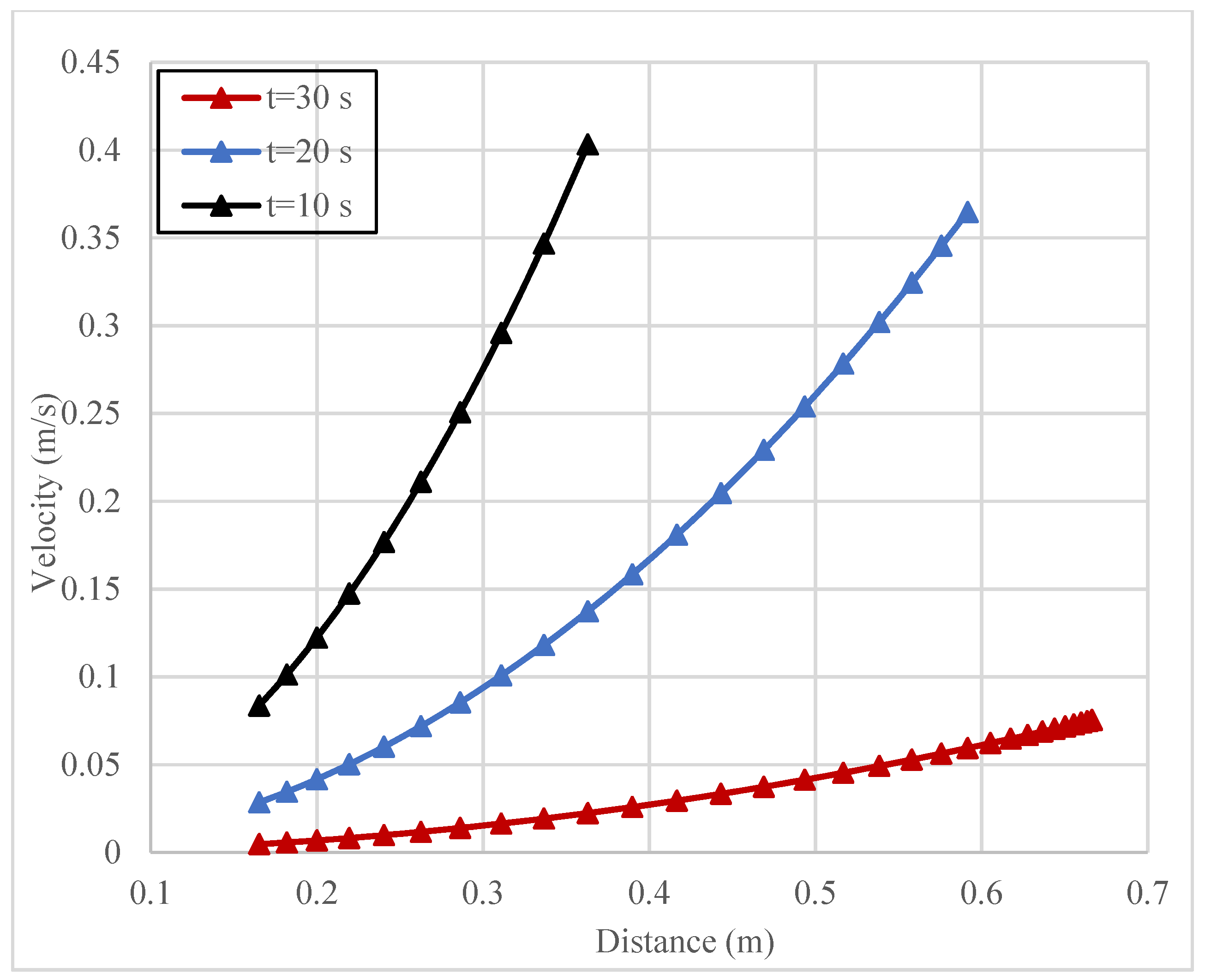
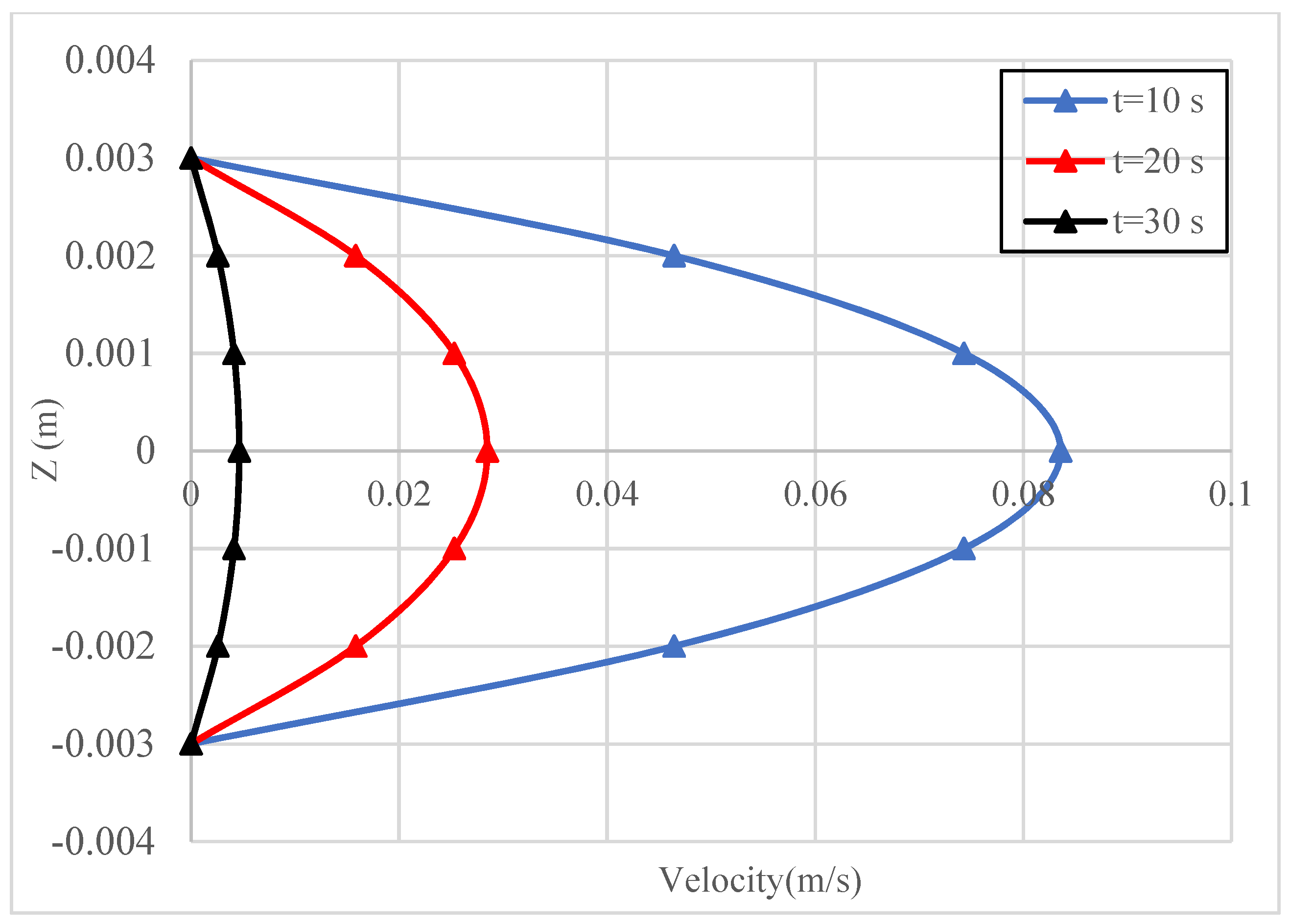
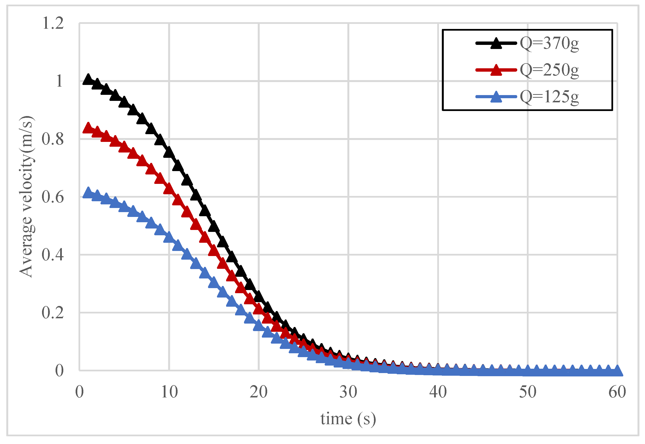
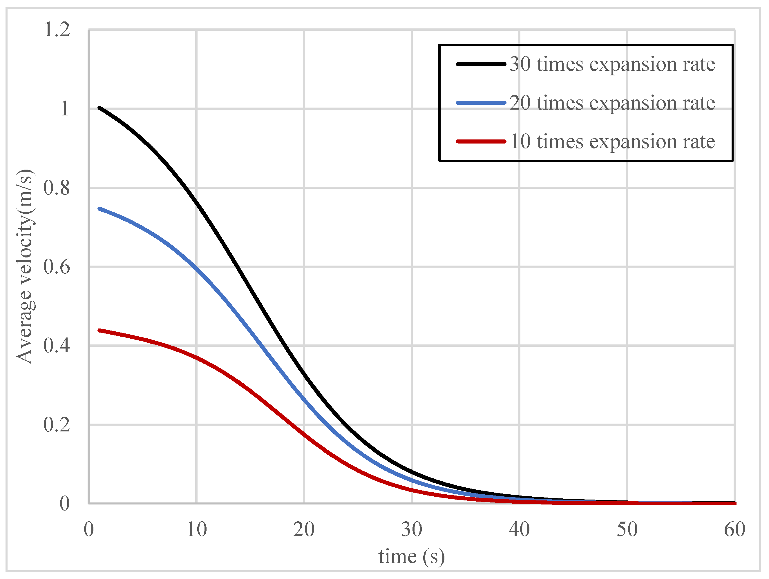
Table 3 shows the flow velocity values at different positions on the fracture section when t = 20 s, which can be described as an intuitive three-dimensional distribution of flow velocity, as shown in Figure 16. It can be seen from Table 3 and Figure 16 that the farther the fracture section is from the grouting hole and the fracture wall, the greater the diffusion pressure is. Figure 17 and Figure 18 show the velocity on temporal and spatial distribution characteristics of slurry. Figure 17 shows the velocity variation of slurry with radial distance at different times. It can be seen from the Figure 17 that the slurry velocity increases along the radial direction, and the velocity reaches the maximum at the interface between slurry and air. Figure 18 shows the velocity variation curve of slurry along the z-axis direction at different times. It can be seen from Figure 18 that the slurry velocity presents a parabolic distribution in the z-axis direction, and the velocity reaches the maximum at the midpoint of the fracture (z = 0) and reaches the minimum at the fracture wall, and the velocity is zero. It can also be seen from Figure 17 and Figure 18 that the slurry flow rate gradually decreases with time and finally becomes zero. Figure 19 and Figure 20 are the time-varying curves of flow velocity at the interface between slurry and air under different grouting amounts and expansion ratios. It can be seen from Figure 19 and Figure 20 that the greater the grouting amount and expansion ratio, the greater the interface flow velocity; the grouting amount and expansion ratio are the key factors affecting the flow velocity.
5. Conclusions
(1) In this paper, the effects of grouting volume, crack opening, radial distance, time, expansion ratio and other factors were fully considered. The radial diffusion model of polymer grouting in a single crack was theoretically deduced, and the theoretical model was verified by the numerical simulation of slurry in parallel plate cracks. The variation laws of slurry diffusion radius and pressure at different times are basically consistent with the analytical solution,
(2) The amount of grouting, the expansion ratio and the crack opening have a great influence on the diffusion law of polymer crack grouting. The diffusion pressure is directly proportional to the grouting amount and expansion ratio, and inversely proportional to the crack opening. In addition, the greater the grouting amount and expansion ratio, the greater the interfacial velocity.
(3) The diffusion pressure is directly proportional to the grouting volume and expansion multiple, and inversely proportional to the crack width. In addition, diffusion pressure decreases with the increase of diffusion distance, and the pressure at the corresponding distance increases slowly with time, eventually reaching stability.
Author Contributions
Conceptualization, J.L. and X.D.; methodology, J.L.; software, J.L.; validation, J.L., X.D. and S.M.; formal analysis, J.L.; investigation, J.L.; resources, J.L.; data curation, J.L.; writing—original draft preparation, J.L.; writing—review and editing, J.L.; visualization, J.L.; supervision, J.L.; project administration, J.L.; funding acquisition, X.D. All authors have read and agreed to the published version of the manuscript.
Funding
This work was supported by the National Natural Science Foundation of China (No. 52008379, 51678536, 41404096), the Postdoctoral research projects in Henan Province (201901012), Supported by the Systematic Project of Guangxi Key Laboratory of Disaster Prevention and Engineering Safety (2020ZDK001) and the Open Research Fund of Guangxi Key Laboratory of Water Engineering Materials and Structures, Guangxi institute of water resources research(GXHRI-WEMS-2020-12); the National Key Research and Development Program of China (No.2017YFC1501204), the National Basic Research Program of China (No.2015CB060200), the Program for Science and Technology Innovation Talents in Universities of Henan Province (Grant No. 19HASTIT043), the Outstanding Young Talent Research Fund of Zhengzhou University (1621323001) and the Program for Innovative Research Team (in Science and Technology) in University of Henan Province (18IRTSTHN007).
Institutional Review Board Statement
Not applicable.
Informed Consent Statement
Not applicable.
Data Availability Statement
The study did not report data.
Acknowledgments
The first author would like to thank the Chinese Scholarship Council for financial support toward his joint at the University of Newcastle, Australia. We would also like to acknowledge the reviewers for their invaluable comments.
Conflicts of Interest
The authors declare that they have no known competing financial interests or personal relationships that could have appeared to influence the work reported in this paper.
References
- Du, X.M.; Fang, H.Y.; Wang, S.Y.; Xue, B.H. Experimental and practical investigation of the sealing efficiency of cement grouting in tortuous fractures with flowing water. Tunn. Undergr. Space Technol. 2021, 108, 103693. [Google Scholar] [CrossRef]
- Algin, H.M. Optimised design of jet-grouted raft using response surface method. Comput. Geotech. 2016, 74, 56–73. [Google Scholar] [CrossRef]
- Maghous, S.; Saada, Z.; Dormieux, L.; Canou, J.; Dupla, J.C. A model for in situ grouting with account for particle filtration. Comput. Geotech. 2006, 34, 164–174. [Google Scholar] [CrossRef]
- Wang, Z.F.; Shen, S.L.; Modoni, G. Enhancing discharge of spoil to mitigate disturbance induced by horizontal jet grouting in clayey soil: Theoretical model and application. Comput. Geotech. 2019, 111, 222–228. [Google Scholar] [CrossRef]
- Wang, S.F.; Tang, Y.; LI, X.B.; Du, K. Analyses and predictions of rock cuttabilities under different confining stresses and rock properties based on rock indentation tests by conical pick. Trans. Nonferrous Met. Soc. China 2021, 31, 1766–1783. [Google Scholar] [CrossRef]
- Wang, S.F.; Tang, Y.; Wang, S.Y. Influence of brittleness and confining stress on rockcuttability based on rock indentation tests. J. Cent. South Univ. 2021, 28, 2786–2800. [Google Scholar] [CrossRef]
- Editorial Committee of Foundation Treatment Manual. Foundation Treatment Manual; China Construction Industry Press: Beijing, China, 1988; pp. 283–287, 331–371. [Google Scholar]
- Shi, M.S. Research on Polymer Grouting Material Properties and Directional Fracturing Grouting Mechanism for Dykes and Dams. Ph.D. Thesis, Dalian University of Technology, Dalian, China, 2011. [Google Scholar]
- El Tani, M. Grouting rock fractures with cement grout. Rock Mech. Rock Eng. 2012, 45, 547–561. [Google Scholar] [CrossRef]
- El Tani, M.; Stille, H. Grout spread and injection period of silica solution and cement mix in rock fractures. Rock Mech. Rock Eng. 2017, 50, 2365–2380. [Google Scholar] [CrossRef]
- Yang, M.J.; Yue, Z.Q.; Lee, P.K.; Su, B.; Tham, L.G. Prediction of grout penetration in fractured rocks by numerical simulation. Can. Geotech. J. 2002, 39, 1384–1394. [Google Scholar] [CrossRef] [Green Version]
- Zhang, Q.S.; Zhang, L.Z.; Liu, R.T. Grouting mechanism of quick setting slurry in rock fissure with consideration of viscosity variation with space. Tunn. Undergr. Space Technol. 2017, 70, 262–273. [Google Scholar] [CrossRef]
- Zhang, L.H. Seepage Mechanism and Mechanics of Geotechnical Grouting. Ph.D. Thesis, Northern Jiaotong University, Beijing, China, 1996. [Google Scholar]
- Li, X.L.; Jin, D.; Wang, F.M.; Zhong, Y.H.; Zhang, B. Diffusion model of an ideal expansible grout in single fracture. Chin. J. Rock Mech. Eng. 2018, 37, 37–1207. [Google Scholar]
- Funehag, J.; Gustafson, G. Design of grouting with silica sol in hard rock-new methods for calculation of penetration length. part I. Tunn. Undergr. Space Technol. 2008, 23, 1–8. [Google Scholar] [CrossRef]
- Li, S.F.; Li, S.C.; Liu, R.T. Grouting reinforcement experiment for water-rich broken rock mass. Chin. J. Rock Mech. Eng. 2017, 36, 198–207. [Google Scholar]
- Ruan, W.J. Spreading model of grouting in rock mass fissures based on time-dependent behavior of viscosity of cement-based grouts. Chin. J. Rock Mech. Eng. 2005, 24, 2709–2714. [Google Scholar]
- Amadei, B.; Savage, W.Z. An analytical solution for transient flow of Bingham viscoplastic materials in rock fractures. Int. J. Rock Mech. Min. Sci. 2001, 38, 285–296. [Google Scholar] [CrossRef]
- Luo, P.P.; Li, Z.P.; Fan, B. Theoretical study on flow model for tilted single fracture Binghamian grout. J. Shandong Univ. Sci. Technol. 2010, 29, 43–47. [Google Scholar]
- Zhan, K.Y.; Sui, W.H.; Gao, Y. A model for grouting into single fracture with flowing water. Rock Soil Mech. 2011, 32, 1659–1663. [Google Scholar]
- Tian, M.X. A model for grouting into fracture with flowing water based on time-dependent behavior of viscosity. J. Chongqing Jiaotong Univ. Nat. Sci. 2011, 30, 536–537. [Google Scholar]
- Zhang, Q.S.; Zhang, L.Z.; Zhang, X. Grouting diffusion in a horizontal crack considering temporal and spatial variation of viscosity. Chin. J. Rock Mech. Eng. 2015, 34, 1198–1210. [Google Scholar]
- Guo, C.C.; Wang, F.M. Mechanism Study on the Construction of Ultra-Thin Antiseepage Wall by Polymer Injection. J. Mater. Civ. Eng. 2012, 24, 1183–1192. [Google Scholar]
- Zheng, C.C. Simulation study on Grouting of Fractured Rock Mass. Ph.D. Thesis, Central South University of Technology, Changsha, China, 1999. [Google Scholar]
- Ruan, W.J. Study on Basic Properties of Grout and Grouting Diffusion in Rock Cracks. Ph.D. Thesis, Jilin University, Changchun, China, 2003. [Google Scholar]
- Zheng, Y.H. Research on Grouting and Grouting Control Method for Fractured Rock Mass. Ph.D. Thesis, Jilin University, Changchun, China, 2005. [Google Scholar]
Figure 1.
Polymer consolidation after reaction.

Figure 2.
Comparison of slurry height before and after reaction.

Figure 3.
Schematic diagram of self-expanded slurry diffusion in flat single fracture.

Figure 4.
Determination of slurry unit.

Figure 5.
Schematic diagram of numerical model of polymer grouting in crack.

Figure 6.
Variation curve of diffusion radius with time under different grouting amounts.

Figure 7.
Simulation results of slurry volume fraction varying with time at different times.

Figure 8.
Variation curve of pressure with diffusion distance at different times.

Figure 9.
Pressure versus time curves at different distances.

Figure 10.
Variation curve of pressure with time under different grouting amount.

Figure 11.
Relation curve between maximum pressure and grouting volume.

Figure 12.
Variation curve of pressure with time under different fracture opening.

Figure 13.
Relation curve between maximum pressure and fracture opening.

Figure 14.
Pressure versus time curves at different expansion ratios.

Figure 15.
Relation curve between maximum pressure and expansion ratio.

Figure 16.
Three -dimensional velocity distribution.

Figure 17.
Variation curve of slurry velocity with radial distance at different time.

Figure 18.
Variation curve of slurry velocity along z-axis at different times.

Figure 19.
Variation curve of velocity at the interface between slurry and air with time under different grouting amount.
Figure 19.
Variation curve of velocity at the interface between slurry and air with time under different grouting amount.

Figure 20.
Variation curve of velocity at the interface between slurry and air with time under different expansion ratios.
Figure 20.
Variation curve of velocity at the interface between slurry and air with time under different expansion ratios.


Table 1.
Simulation results and analytical results of pressure distribution at different times.
| Position r (cm) | Time t (s) | Diffusion Pressure (KPa) | Relative Error | |
|---|---|---|---|---|
| Numerical Solution | Theoretical Solution | |||
| r = 2 | 0 | 0.3554 | 0.3589 | 0.9% |
| 10 | 0.3591 | 0.3604 | 0.4% | |
| 20 | 0.3634 | 0.3636 | 0.1% | |
| 30 | 0.3652 | 0.3650 | 0.1% | |
| 40 | 0.36581 | 0.3653 | 0.1% | |
| 50 | 0.3662 | 0.3653 | 0.2% | |
| 60 | 0.3662 | 0.3653 | 0.2% | |
Table 2.
Simulation results and analytical results of radial pressure distribution at different positions.
Table 2.
Simulation results and analytical results of radial pressure distribution at different positions.
| Time t (s) | Position r (cm) | Diffusion Pressure (KPa) | Relative Error | |
|---|---|---|---|---|
| Numerical Solution | Theoretical Solution | |||
| t = 30 | 2 | 0.3630 | 0.3651 | 0.5% |
| 4 | 0.3592 | 0.3643 | 0.5% | |
| 6 | 0.3579 | 0.3629 | 1.3% | |
| 8 | 0.3560 | 0.3610 | 1.0% | |
| 10 | 0.3535 | 0.3585 | 1.3% | |
| 12 | 0.3506 | 0.3556 | 1.0% | |
| 14 | 0.3470 | 0.3520 | 1.4% | |
Table 3.
Velocity values at different positions on the fracture section.
| Position(x)/m | z/m | ||||||
|---|---|---|---|---|---|---|---|
| −0.0030 | −0.0020 | −0.0010 | 0.0000 | 0.0010 | 0.0020 | 0.0030 | |
| 0.1653 | 0 | 0.0158 | 0.0253 | 0.0285 | 0.0253 | 0.0158 | 0 |
| 0.1820 | 0 | 0.0192 | 0.0307 | 0.0345 | 0.0307 | 0.0192 | 0 |
| 0.2000 | 0 | 0.0232 | 0.0370 | 0.0417 | 0.0370 | 0.0232 | 0 |
| 0.2195 | 0 | 0.0279 | 0.0446 | 0.0502 | 0.0446 | 0.0279 | 0 |
| 0.2404 | 0 | 0.0334 | 0.0535 | 0.0602 | 0.0535 | 0.0334 | 0 |
| 0.2627 | 0 | 0.0399 | 0.0639 | 0.0719 | 0.0639 | 0.0399 | 0 |
| 0.2862 | 0 | 0.0474 | 0.0759 | 0.0854 | 0.0759 | 0.0474 | 0 |
| 0.3110 | 0 | 0.0560 | 0.0896 | 0.1008 | 0.0896 | 0.0560 | 0 |
| 0.3367 | 0 | 0.0656 | 0.1050 | 0.1181 | 0.1050 | 0.0656 | 0 |
| 0.3631 | 0 | 0.0763 | 0.1221 | 0.1373 | 0.1221 | 0.0763 | 0 |
| 0.3899 | 0 | 0.0880 | 0.1408 | 0.1584 | 0.1408 | 0.0880 | 0 |
| 0.4167 | 0 | 0.1005 | 0.1608 | 0.1809 | 0.1608 | 0.1005 | 0 |
| 0.4432 | 0 | 0.1137 | 0.1819 | 0.2046 | 0.1819 | 0.1137 | 0 |
| 0.4689 | 0 | 0.1273 | 0.2037 | 0.2291 | 0.2037 | 0.1273 | 0 |
| 0.4936 | 0 | 0.1410 | 0.2256 | 0.2538 | 0.2256 | 0.1410 | 0 |
| 0.5168 | 0 | 0.1546 | 0.2474 | 0.2783 | 0.2474 | 0.1546 | 0 |
| 0.5384 | 0 | 0.1678 | 0.2684 | 0.3020 | 0.2684 | 0.1678 | 0 |
| 0.5581 | 0 | 0.1803 | 0.2884 | 0.3245 | 0.2884 | 0.1803 | 0 |
| 0.5758 | 0 | 0.1919 | 0.3071 | 0.3455 | 0.3071 | 0.1919 | 0 |
| 0.5916 | 0 | 0.2026 | 0.3241 | 0.3646 | 0.3241 | 0.2026 | 0 |
Publisher’s Note: MDPI stays neutral with regard to jurisdictional claims in published maps and institutional affiliations. |
© 2021 by the authors. Licensee MDPI, Basel, Switzerland. This article is an open access article distributed under the terms and conditions of the Creative Commons Attribution (CC BY) license (https://creativecommons.org/licenses/by/4.0/).
Share and Cite
MDPI and ACS Style
Liang, J.; Ma, S.; Du, X. Diffusion Model of Parallel Plate Crack Grouting Based on Foaming Expansion Characteristics of Polymer Slurry. Mathematics 2021, 9, 2907. https://0-doi-org.brum.beds.ac.uk/10.3390/math9222907
AMA Style
Liang J, Ma S, Du X. Diffusion Model of Parallel Plate Crack Grouting Based on Foaming Expansion Characteristics of Polymer Slurry. Mathematics. 2021; 9(22):2907. https://0-doi-org.brum.beds.ac.uk/10.3390/math9222907
Chicago/Turabian StyleLiang, Jiasen, Shaokun Ma, and Xueming Du. 2021. "Diffusion Model of Parallel Plate Crack Grouting Based on Foaming Expansion Characteristics of Polymer Slurry" Mathematics 9, no. 22: 2907. https://0-doi-org.brum.beds.ac.uk/10.3390/math9222907
Note that from the first issue of 2016, this journal uses article numbers instead of page numbers. See further details here.