Article

Complementary Split-Ring Resonator for Microwave Heating of µL Volumes in Microwells in Continuous Microfluidics

1
Advanced RF, IMEC, 3001 Heverlee, Belgium
2
Division WaveCore, Department of Electrical Engineering (ESAT), KU Leuven, 3001 Leuven, Belgium
*
Author to whom correspondence should be addressed.
Submission received: 20 June 2021 / Revised: 12 July 2021 / Accepted: 15 July 2021 / Published: 17 July 2021
(This article belongs to the Special Issue Microfluidic Biosensing Platform)

Abstract

:
This work presents the design and evaluation of a planar device for microwave heating of liquids in continuous microfluidics (CMF) made in polydimethylsiloxane (PDMS). It deals with volumes in the µL range, which are of high interest and relevance to biologists and chemists. The planar heater in this work is conceived around a complementary split-ring resonator (CSRR) topology that offers a desired electric field direction to—and interaction with—liquids in a microwell. The designed device on a 0.25 mm thick Rogers RO4350B substrate operates at around 2.5 GHz, while a CMF channel and a 2.45 µL microwell are manufactured in PDMS using the casting process. The evaluation of the performance of the designed heater is conducted using a fluorescent dye, Rhodamine B, dissolved in deionized water. Heating measurements are carried out using 1 W of power and the designed device achieves a temperature of 47 °C on a sample volume of 2.45 µL after 20 s of heating. Based on the achieved results, the CSRR topology has a large potential in microwave heating, in addition to the already demonstrated potential in microwave dielectric sensing, all proving the multifunctionality and reusability of single planar microwave-microfluidic devices.

1. Introduction

Microwave heating gained momentum in the mid-20th century with the invention of the tabletop microwave oven, Amana RR-1, which was sold at the time for $495. Since then, the microwave oven found a way to numerous households around the globe. Moreover, it found the way to chemistry and made an impact that resulted in a new research domain called microwave-assisted organic chemistry [1], in which the microwave oven and its derivatives were used for studying chemical reactions under different heating conditions. Aside from applications in chemistry, microwave heating has recently been adopted for lab-on-chip devices within the research domain of micro-total-analysis systems for life sciences [2]. In lab-on-a-chip devices, several tasks, usually carried out in laboratories by trained personnel, are transferred and performed on a chip that is as large as a credit card with miniature fluidic channels originating from the microfluidics research domain. The motivation for the research and development of microwave heating devices for lab-on-a-chip systems is multifold: (1) microwave heating is not dependent on the thermal conductivity of materials, (2) it does not require physical contact between the liquid and the heater, and (3) it offers large heating rates with high power efficiencies, all resulting in rapid biological and chemical reactions.
Microwave heaters for continuous microfluidics were, up to now, developed for picoliter and nanoliter droplets [3,4,5,6] in miniature continuous microfluidics (CMF) channels. To achieve rapid heating of droplets, planar resonators [3,4], interdigitated capacitors [5], and coupled lines were used [6]. All the reported results represent a significant achievement in this domain. Yet, they do not deal with the heating of sub-microliter to microliter range volumes in CMF, which are of high interest to biologists and flow chemists as larger volumes than picoliter droplets are needed for reactions such as polymerase chain reaction [7], and the generation of various products in chemical reactions [8]. Up to now, there has been only a limited amount of work presented for microwave heating sub-microliter volume. Markovic et al. [9,10] reported devices that can heat 0.2–0.5 μL at 25 GHz in a glass-silicon device using transmission lines (TLs), Shaw et al. [11] presented a cavity resonator for the heating of 0.7 μL at 8 GHz, and Marchiarullo et al. [12] reported work on microwave heating using an open-ended microstrip transmission line for a 1.3 μL volume at 5.5 GHz, while Morgan et al. [13] reported the heating of a complete fluidic chip with a volume of 20 μL at 2.45 GHz in a cavity. The summary of the state-of-the-art review is shown in Table 1. Additionally, there has been limited attention given to heating uniformity, on which the outcomes of biological and chemical reactions depend significantly.
The previously reported work required a complex and expensive manufacturing process involving silicon [9,10] and bulky cavities in which selective heating was not possible [13], and offered limited scalability due to the size of the microwave structures [12]. In this work, we focus on a planar microwave topology that requires readily available and affordable manufacturing technology with a high scaling potential and efficient use of the chip area. Thus, we chose the complementary split-ring resonator (CSRR) topology and the printed circuit board (PCB) lithography process in combination with CMF prototyping using polydimethylsiloxane (PDMS) and the casting process. In summary, once this work is compared to the state-of-the-art summary in Table 1, it can be concluded that for a relatively minimal cost in performance, a new topology that offers readily affordable manufacturing, scalability, and optical inspection of the sample during the heating is demonstrated.
The CSRRs were, up to now, mostly used for dielectric sensing and numerous designs were presented, which operated at different frequencies [14,15,16,17,18,19,20,21]. It was only partially that CSRR was developed for heating in the context of microwave hyperthermia (temperatures from 41 to 45 °C) [22,23,24,25,26,27]. Nevertheless, according to our best knowledge, a CSRR topology has not yet been used for microwave heating in CMF. Therefore, we mainly focus on a design of a CSRR for uniform microwave heating and secondly on microwave dielectric sensing to demonstrate the versatility and reusability of microwave-microfluidic devices.
In this work, the CSRR sensing capabilities are demonstrated using demineralized water, physiological liquid, glucose solution and isopropyl alcohol, all having different complex permittivities and conductivities. The heating performance of the developed device is evaluated using a mixture of demineralized water and a temperature-dependent fluorescent dye, Rhodamine B, at a concentration of 1 mmol/L [28,29]. The CSRR microwave heater achieves the temperature of 47 °C on a sample volume of 2.45 µL after 20 s of heating. The sensing results on a sample volume of 2.45 µL demonstrate a resonant frequency shift of 5.7 MHz per arbitrary unit of relative permittivity. In conclusion, the developed device demonstrates a heating result that is relevant to biology and chemistry, and requires rapid heating combined with dielectric sensing.

2. Materials and Methods

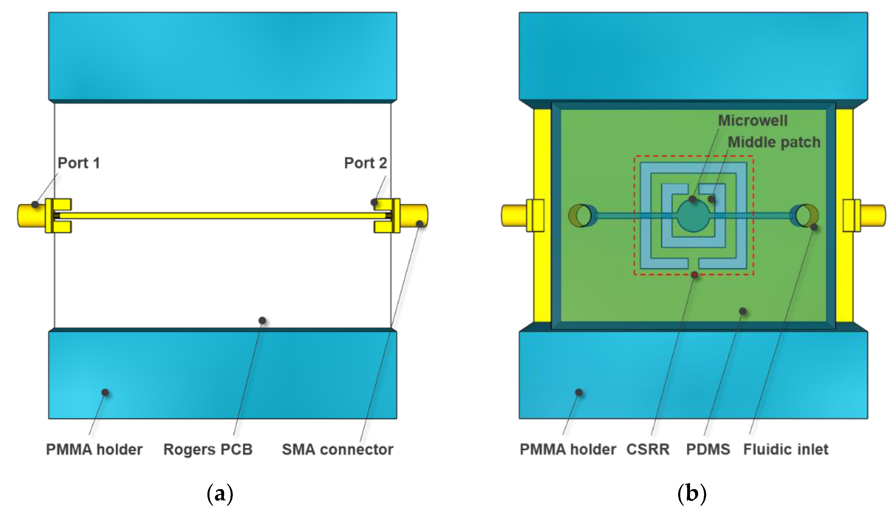
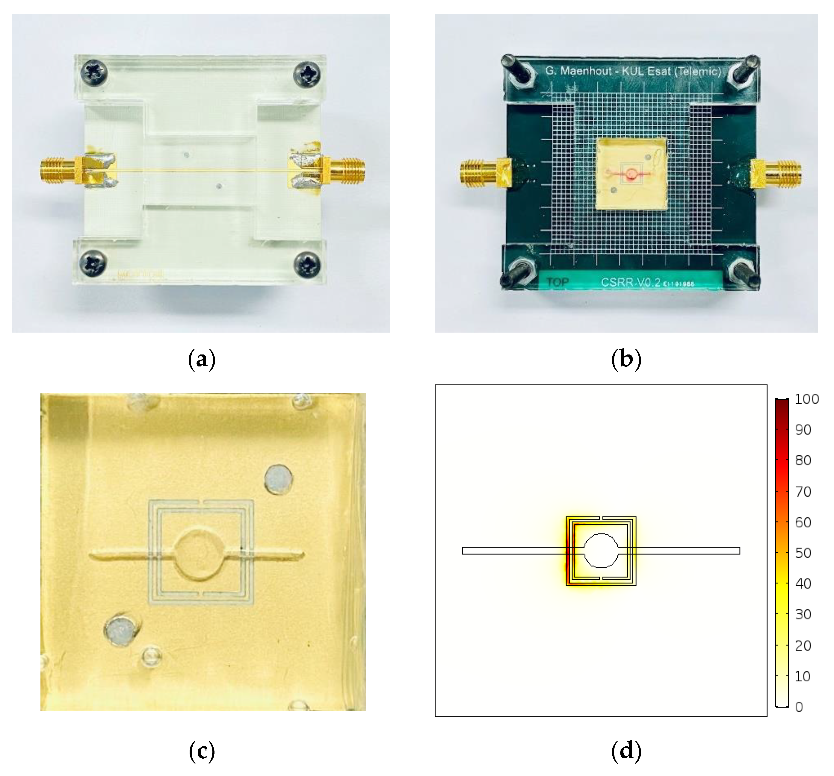
2.1. Device Fabrication, Integration and Measurements

The CSRR is fabricated using the in-house available lithography process on a 0.25 mm thick Rogers RO4350B substrate (Evergem, Belgium) with 18 µm thick copper cladding. The CMF channel and the microwell are manufactured using PDMS and the casting process in a poly (methyl methacrylate) (PMMA) mold manufactured using the in-house available Trotec laser cutters. The printed circuit board (PCB) with the CSRR and the PDMS microchannel are bonded together using a thin layer of PDMS and fixed together to a PMMS holder to ensure mechanical stability, as depicted in Figure 1. End launch subminiature version A (SMA) coaxial connectors are soldered onto the PCB for interconnection with microwave measurement equipment. The Tygon tubing, in combination with metal inserts, is used to feed the liquid to the CMF channel and the microwell.
The manufactured devices are evaluated using a Keysight M9735A vector network analyzer (VNA), a 2–8 GHz BSW Test System & Consulting power amplifier (Boxmeer, the Netherlands), an Olympus IX73 microscope (Antwerp, Belgium), a Hamamatsu Orca-Flash4.0 LT+ digital camera (Mont-Saint-Guibert, Belgium), a CoolLED pe-4000 light source (Andover, United Kingdom) and a Pico Elite syringe pump [24] (Holliston, MA, USA).

2.2. Heater Design

The microwave-microfluidic heater is designed based on the CSRR topology that originates from the metamaterial domain, in which reactive components or small resonators are used to modify the characteristic impedance and dispersion of transmission lines [30]. The CSRR is a planar structure consisting of a microstrip transmission line with a defected ground plane, depicted in Figure 2a, that can be modeled with an equivalent electric circuit incorporating a parallel resonant circuit that is capacitively coupled to a transmission line [31], shown in Figure 2b. Based on the shape and size of the deformation in the ground plane, this is a resonant circuit.
In other words, once an electromagnetic wave is supplied at port 1, see Figure 1a,b, a resonance takes place at the CSRR, indicated in Figure 1b. During the resonance of the CSRR, a perpendicular electric field is formed over the middle patch, which penetrates deep into the liquid, as illustrated in Figure 2c. This alternating electric field forces the polar molecules in the liquid to align to the imposed electric field. During the rotation, a part of the electromagnetic wave power is dissipated during the friction between the molecules that generates heat, and the remaining part is transmitted to port 2 once terminated with a 50 Ohm load. In the case when port 2 is terminated by a short circuit, or left open, the electromagnetic wave at port 2 is reflected back into the circuit and, once again, a part of the wave is dissipated into the heat and the remaining part is transmitted to port 1. This means that the CSRR can be used for heating of a liquid loaded in a single microwell, or multiple CSRRs can be cascaded for heating of liquids in multiple microwells through the heating mechanisms of ports 1 and 2.
In this work, we have opted for a square CSRR geometry for the microwave device for the heating of liquid in a single microwell through the port 1 heating mechanism, in which the waves are reflected at port 2. The design of the heater is conducted around several interconnected parameters, which are shown in Figure 2a. By changing the size of the middle patch A, the CSRR size W, the spacing between the metal lines S, the thickness of the rings T, and the size of the interconnected patch G, a resonant frequency and, consequently, the electric field strength sourced from the middle patch (illustrated in Figure 2c), responsible for microwave heating, are varied. In this work, the design of CSRR is undertaken in combination with a CMF microwell using COMSOL Multiphysics.

3. Results

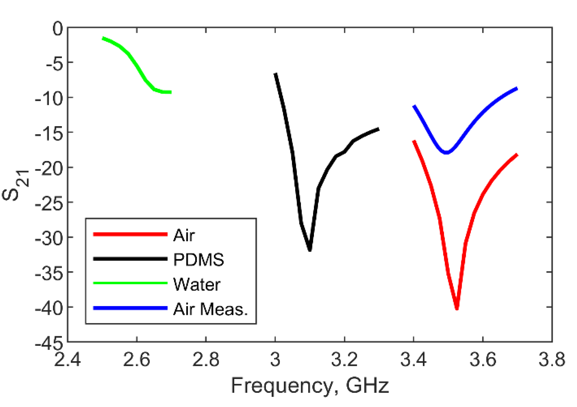
3.1. Microwave CSRR Heater

The CSRR sources a perpendicular electric field that originates from the middle patch into the liquid in our stack-up. To maximally exploit this electric field, the design of the CSRR heater starts from the schematic and equivalent circuit in Figure 2a,b. Port P1 is chosen to be the excitation port, while port P2 is chosen to be left open so that a standing wave pattern along the structure is formed. In other words, a part of the microwave power sourced at port P1 is dissipated into heat by the CSRR and the other part is transmitted to port P2 over the microstrip transmission line. Nevertheless, if P2 is left open, this amount of power, to be transmitted out of port 2, is fed back into the circuit and once again is partially dissipated into heat and partially transmitted to P1. Thus, in addition to the W, A, S, T, G parameters of the CSRR, a characteristic impedance of the line Z0 and its length l2 can be also used in the design to maximize the heating efficiency.
The schematic of the CSRR in Figure 2a is used to design a microwave heater in COMSOL Multiphysics for a microwell large 2.5 mm in diameter and 0.5 mm in height, resulting in a volume of 2.45 µL. The microfluidic channel is chosen to be 0.5 mm × 0.5 mm. These dimensions are chosen because the PDMS slab with the microwell and a channel is manually positioned to a PCB that has the CSRR heater. Thus, all chosen dimensions allow comfortable manual positioning and bonding of the PDMS slab to the PCB. The CSRR in COMSOL Multiphysics is designed to operate around 3.5 GHz and 3.1 GHz for air and PDMS covered device, respectively, for P2 being terminated with 50 Ohm. Once the microwell and microchannel loaded by a liquid are incorporated into the PDMS slab, the operating frequency shifts to around 2.65 GHz. The design values of W = 5 mm, A = 3.8 mm, S = 0.2 mm, T = 0.2 mm, and G = 0.2 mm were found to satisfy the design criteria, while the Z0 and l2 are chosen to be 50 Ohm and 26 mm, respectively. At this stage of the research of CSRR for heating applications, we did not focus intensively on the study of l2 as this length can be fine-tuned using additional microwave transmission lines.
A few studies were reported with respect to the frequency choice [5,9] for heating applications, and in this work, we are focusing on a frequency point around 2.5 GHz, given the commercially available microwave power sources and the freedom to operate, because 2.5 GHz is in the industrial, scientific, and medical (ISM) band. The manufactured device on a Rogers RO4350B substrate and the electric field strength in a microwell are shown in Figure 3, while the simulated scattering (S) parameters of the CSRR covered by air, the PDMS and the microwell loaded with water are shown in Figure 4.

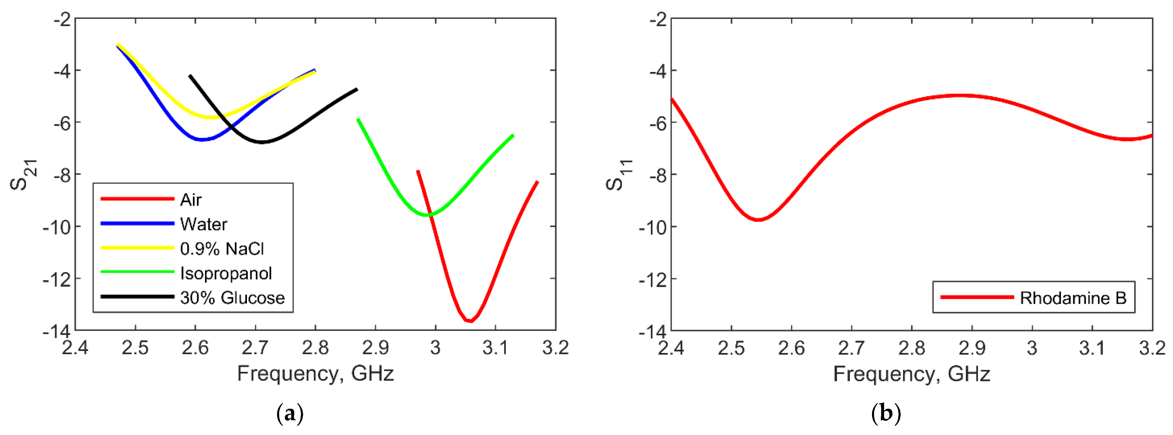
3.2. Microwave Dielectric Sensing

It has been already demonstrated that the CSRR topology has a large potential in measurements of various liquids [14,15,16,17,18,19,20,21]. Thus, the CSRR design is evaluated in transmission measurements (S21) for microwell loaded with different liquids. The scattering parameter S21 represents the ratio of waves exiting port 2 and waves entering port 1. Namely, the device shown in Figure 3 is loaded with demineralized water, physiological liquid (0.9% NaCl), 30% Kela glucose solution and isopropyl alcohol. It can be observed from the data in Figure 5a that the resonant frequency shifts for 450 MHz for the empty (air, permittivity 1) and water (permittivity 78.5 around 2.5 GHz) loaded microwell, resulting in a frequency shift of 5.7 MHz per a.u. of relative permittivity. Moreover, if the simulated and measured resonant frequency in Figure 4 and Figure 5a are compared, a good agreement can be observed.
In addition to transmission measurements (S21), the CSRR is evaluated in reflection measurements at port P1 (S11) once port P2 is left open and the microwell is loaded with a mixture of water and Rhodamine B. The scattering parameter S11 represents the ratio of waves exiting and entering port 1. It is possible to observe from the data in Figure 5b that S11 is relatively small around 2.5 GHz, which means that the microwave power supplied at port 1 is dissipated in the liquid loaded into the microwell and, thus, there is no need to tune the length l2 of the second transmission lines to achieve more efficient heating at this stage.

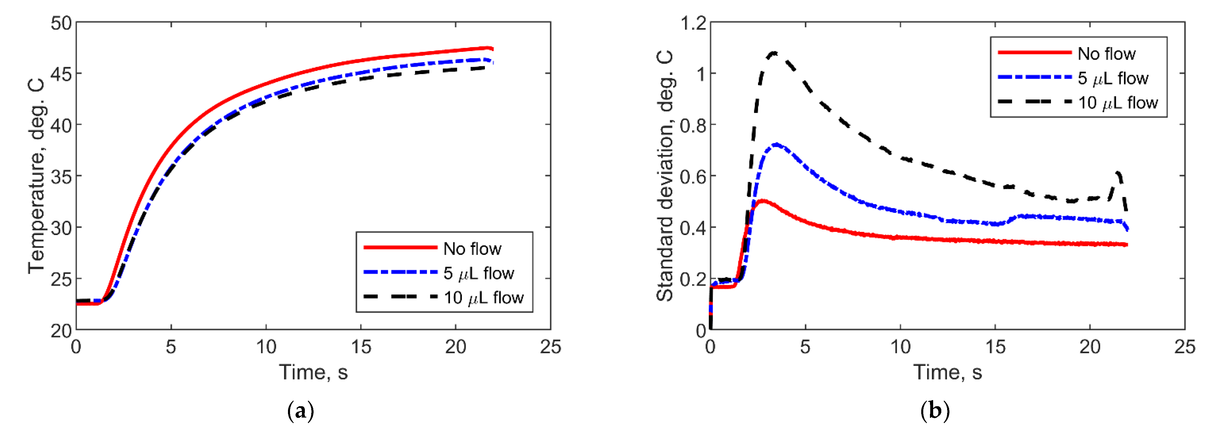
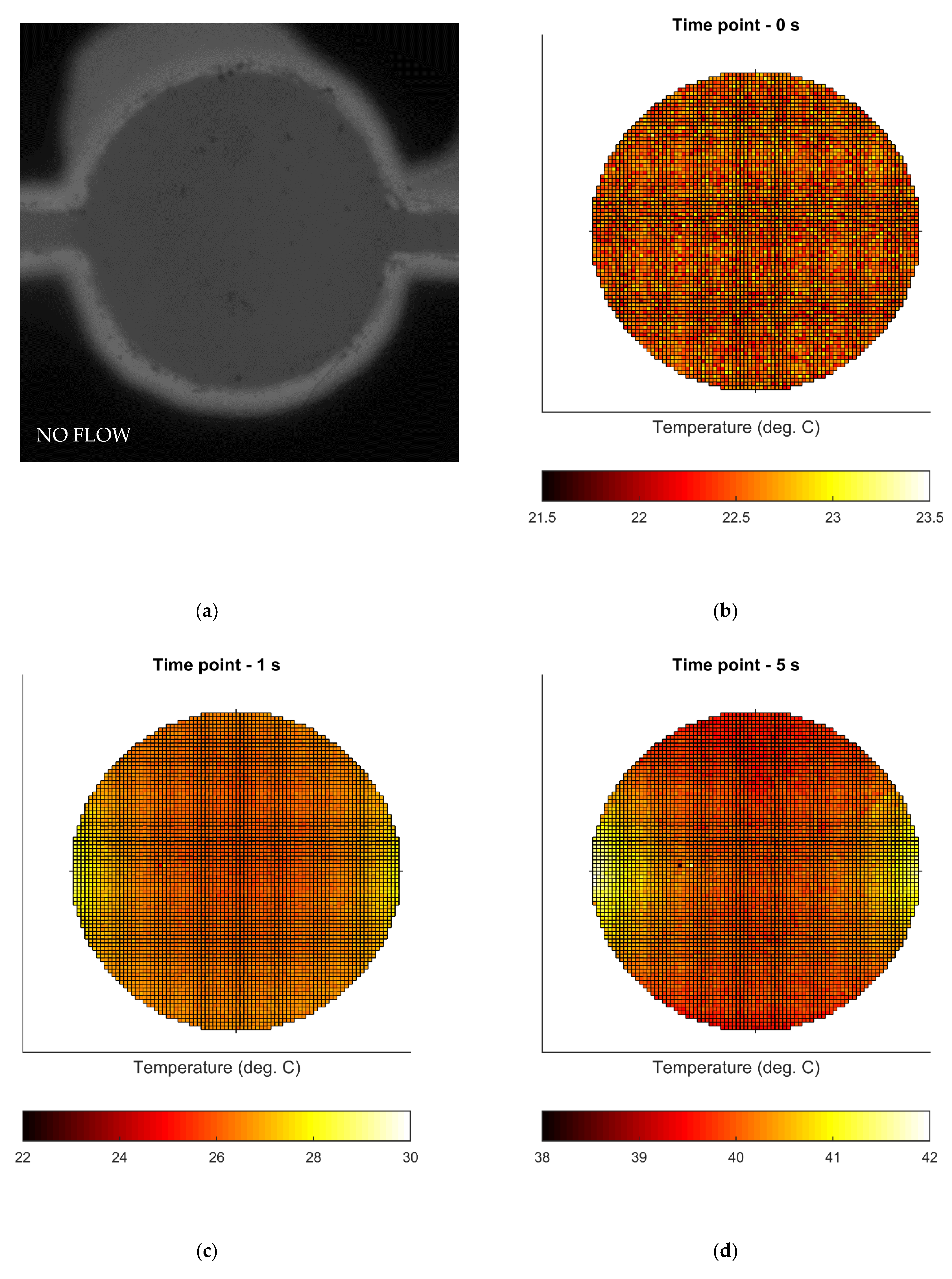
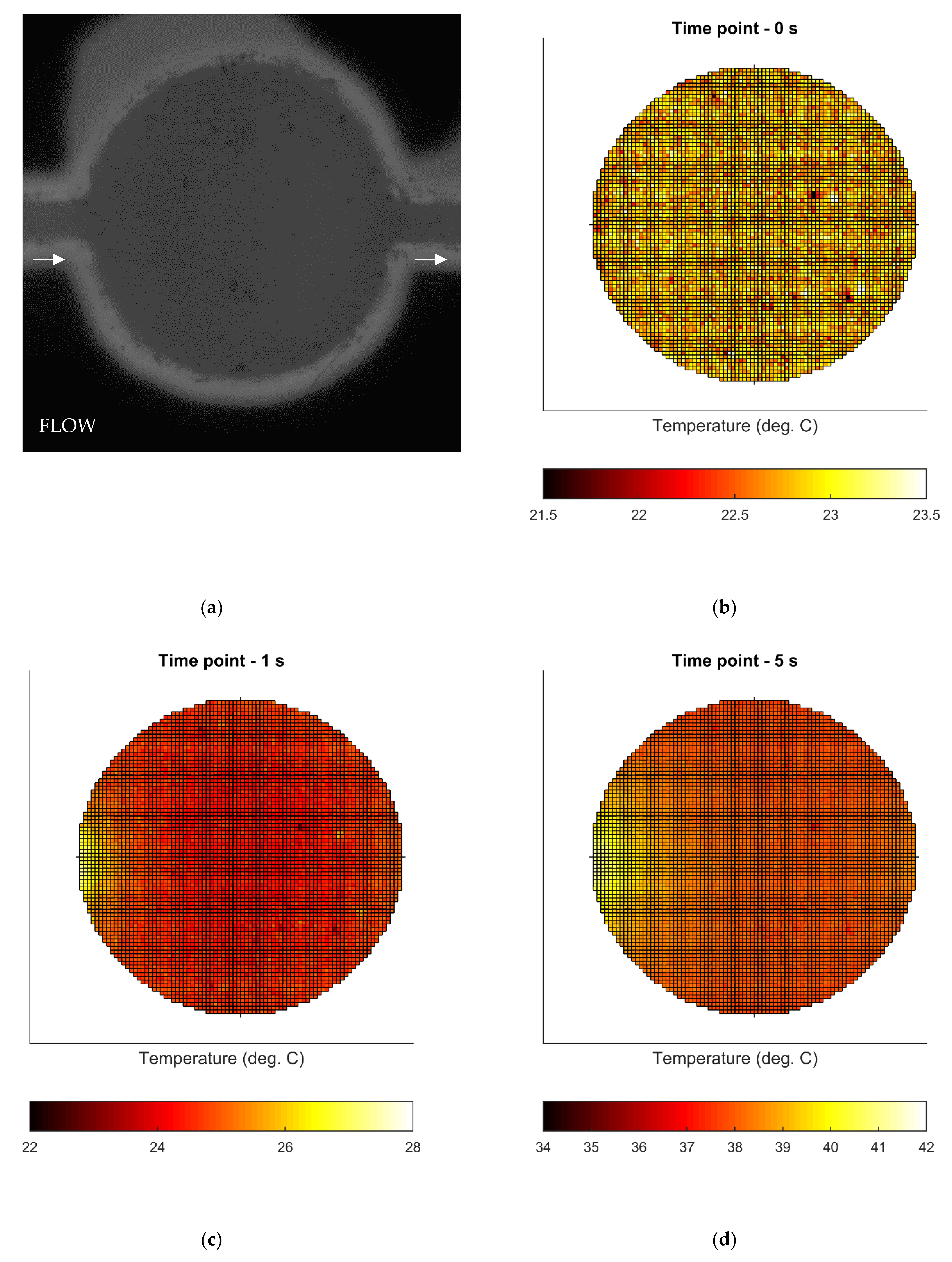
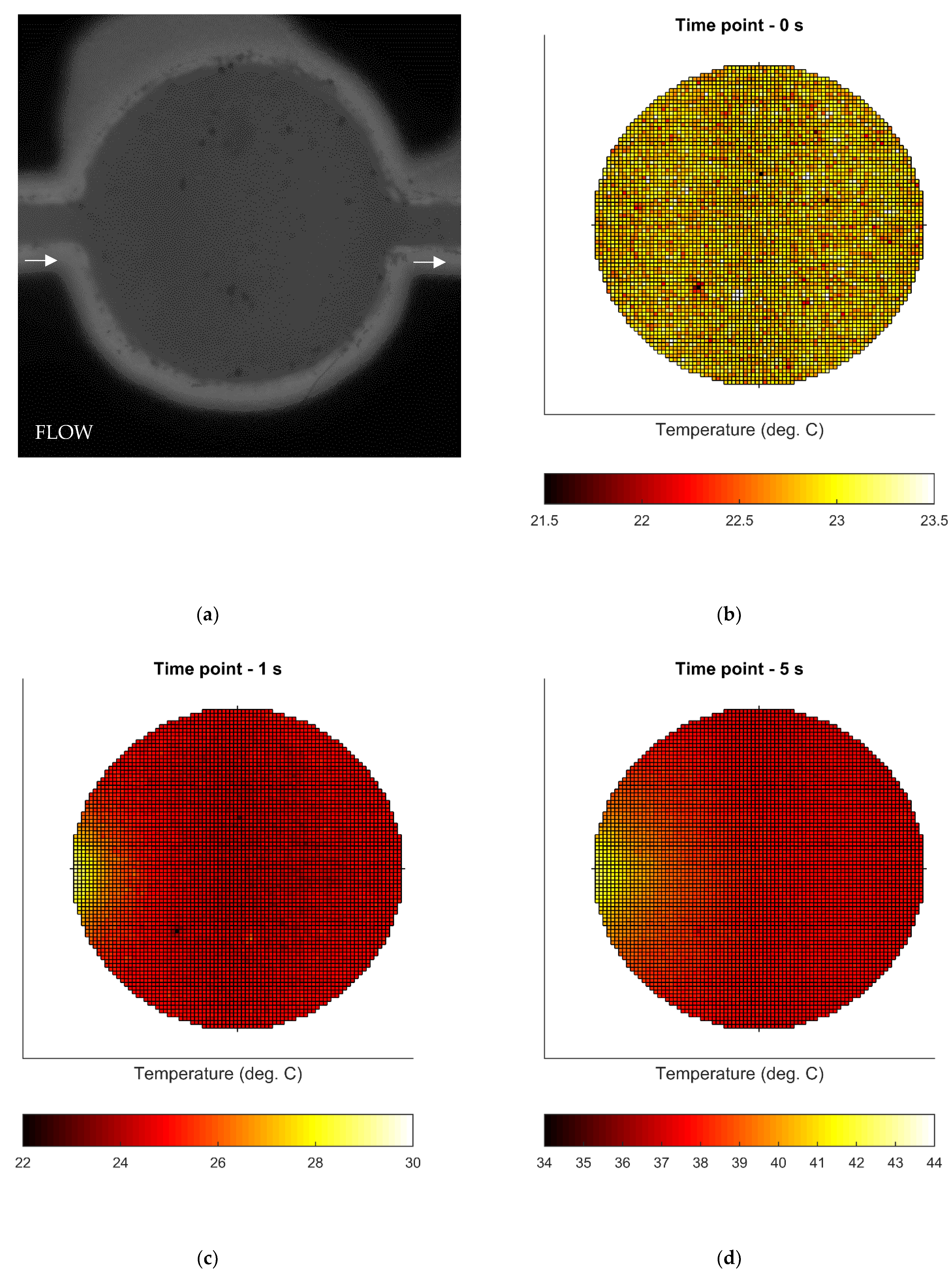
3.3. Microwave Heating Experiments

Microwave heating experiments are carried out with the CSRR loaded with a mixture of demineralized water and Rhodamine B at a concentration of 1 mmol/L. Rhodamine B is a temperature-sensitive fluorescent dye and its temperature–fluorescence dependency [27] can be exploited for in-situ measurements of temperature and temperature uniformity. Moreover, once the fluorescent dye is combined with a fast camera, rapid heating ramps can be also measured given that there is no thermal mass of a temperature sensor involved in the measurement setup.
Three different heating scenarios are considered in this work: (1) the liquid is not moving in the microchannel, (2) the liquid is moving at the flow rate of 5 µL/min, (3) the liquid is moving at the flow rate of 10 µL/min. Before the heating measurements, the liquid mixture is loaded into the microwell, and the temperature of the complete chip is measured using a T-type thermocouple and a National Instruments TC-01 reader. In between all measurements, the liquid is flushed for several minutes, and time is taken for the complete chip to cool down and come to the initial state at the laboratory temperature.
The heating measurements in all scenarios are carried out at 2.5 GHz with a power level of 1 W supplied to port P1. The image of the fluorescent liquid with the corresponding temperature measurement and temperature–fluorescence calibration curve are used to calculate the temperature of the liquid during the heating. The average temperature of the liquid and standard deviation is presented in Figure 6a,b for the previously described measurement scenarios. The detailed temperature profiles at different time points during the heating experiments are shown in Figure 7, Figure 8 and Figure 9. In addition, the images of the fluorescent liquid loaded into the microwell, taken by the camera, are shown.

4. Discussion

The data shown in Figure 6, Figure 7, Figure 8 and Figure 9 show that the CSRR heater achieves uniform heating over the middle patch, which is in accordance with the conclusions from the theoretical study of the CSRR topology. After 20 s of heating at 2.5 GHz, the CSRR heater achieves a temperature of 47 °C. In the initial state of heating, the liquid mixture loaded into the microwell becomes heated and, in the later stages of the heating, the heat is transferred to the surrounding PDMS slab in all measurement’s scenarios due to the large temperature gradient between the liquid and its surroundings.
It is possible to observe that the temperature profiles in Figure 7 have two tails, on the left and right side of the circle, that originate from the heating, taking place in the gap, that is crossed by the microfluidic channel. The heating in the gap is, in general, stronger than over the patch due to the stronger electric field interacting with a smaller volume, which is opposite to the interaction taking place over the middle patch. This effect can be easily avoided in future design improvements by routing the microfluidic channel away from the gaps.
It is also possible to observe that these two tails are reduced to only one in measurement scenarios 2 and 3 (data shown in Figure 8 and Figure 9), since the mixture is flowing in these measurement campaigns. The overall effect of the tails is on the temperature uniformity, which can be seen from data in Figure 6b. In the later stages of heating process, the liquid heating in the gap is mixed in the microwell with the warm liquid, and the overall temperature uniformity improves.
In summary, the CSRR achieves the expected excellent heating results in terms of heating uniformity over a volume with a large surface-to-volume ratio. The overall temperature and further heating efficiency can be tuned by the supplied microwave power for heating and the length of the second transmission line, l2, shown in Figure 2b. In addition to excellent heating results, the CSRR demonstrates significant potential in sensing applications as it achieves an average resonant frequency shift of 5.7 MHz per arbitrary unit of relative permittivity of the loaded liquid into the microwell.

Author Contributions

Conceptualization, T.M. and G.M.; methodology, T.M. and G.M.; validation, T.M., G.M. and M.M.; formal analysis, T.M., G.M. and M.M.; investigation, T.M. and G.M.; resources, T.M. and B.N.; writing—original draft preparation, T.M.; writing—review and editing, G.M., M.M. and B.N.; visualization, T.M.; supervision, T.M.; funding acquisition, T.M. and B.N. All authors have read and agreed to the published version of the manuscript.

Funding

This research was funded by the Research Foundation Flanders (FWO) for funding through a PhD fellowship under the grant number 1S23918N (Gertjan Maenhout) and an FWO Research Project under the grant number G0A1220N (MISTIQUE).

Institutional Review Board Statement

Not applicable.

Informed Consent Statement

Not applicable.

Acknowledgments

We would like to acknowledge the FabLab at KU Leuven for helping with the manufacturing of all mechanical holders.

Conflicts of Interest

The authors declare no conflict of interest.

References

  1. Kappe, C.O. My Twenty Years in Microwave Chemistry: From Kitchen Oven to Microwaves That Aren’t Microwaves. Chem. Rec. 2019, 19, 15–39. [Google Scholar] [CrossRef]
  2. Miralles, V.; Huerre, A.; Malloggi, F.; Jullien, M.-C. A Review of Heating and Temperature Control in Microfluidic Systems: Techniques and Applications. Diagnostics 2013, 3, 33–67. [Google Scholar] [CrossRef] [Green Version]
  3. Boybay, M.S.; Jiao, A.; Glawdel, T.; Ren, C.L. Microwave Sensing and Heating of Individual Droplets in Microfluidic Devices. Lab Chip 2013, 13, 3840–3846. [Google Scholar] [CrossRef]
  4. Abduljabar, A.A.; Choi, H.; Barrow, D.A.; Porch, A. Adaptive Coupling of Resonators for Efficient Microwave Heating of Microfluidics Systems. IEEE Trans. Microw. Theory Technol. 2015, 63, 3681–3690. [Google Scholar] [CrossRef]
  5. Markovic, T.; Bao, J.; Maenhout, G.; Ocket, I.; Nauwelaers, B. An Interdigital Capacitor for Microwave Heating at 25 GHz and Wideband Dielectric Sensing of nL Volumes in Continuous Microfluidics. Sensors 2019, 19, 715. [Google Scholar] [CrossRef] [PubMed] [Green Version]
  6. Issadore, D.; Humphry, K.J.; Brown, K.A.; Sandberg, L.; Weitz, D.A.; Westervelt, R.M. Microwave Dielectric Heating of Drops in Microfluidic Devices. Lab Chip 2009, 9, 1701–1706. [Google Scholar] [CrossRef] [PubMed] [Green Version]
  7. Phaneuf, C.R.; Oh, K.; Pak, N.; Saunders, D.C.; Conrardy, C.; Landers, J.P.; Tong, S.; Forest, C.R. Sensitive, Microliter PCR with Consensus Degenerate Primers for Epstein Barr Virus Amplification. Biomed. Microdevices 2016, 15, 221–231. [Google Scholar] [CrossRef]
  8. Wang, J.; Chao, P.H.; Hanet, S.; van Dam, R.M. Performing Multi-Step Chemical Reactions in Microliter-Sized Droplets by Leveraging a Simple Passive Transport Mechanism. Lab Chip 2019, 17, 4342–4355. [Google Scholar] [CrossRef] [PubMed]
  9. Markovic, T.; Ocket, I.; Baric, A.; Nauwelaers, B. Design and Comparison of Resonant and Non-Resonant Single-Layer Microwave Heaters for Continuous Flow Microfluidics in Silicon-Glass Technology. Energies 2020, 13, 2635. [Google Scholar] [CrossRef]
  10. Markovic, T.; Ocket, I.; Jones, B.; Nauwelaers, B. Characterization of a Novel Microwave Heater for Continuous Flow Microfluidics Fabricated on High-Resistivity Silicon. In Proceedings of the 2016 IEEE MTT-S International Microwave Symposium (IMS), San Francisco, CA, USA, 22–27 May 2016. [Google Scholar]
  11. Shaw, K.J.; Docker, P.T.; Yelland, J.V.; Dyer, C.E.; Greenman, J.; Greenway, G.M.; Haswell, S.J. Rapid PCR Amplification Using a Microfluidic Device with Integrated Microwave Heating and Impingement Cooling. Lab Chip 2010, 10, 1725–1728. [Google Scholar] [CrossRef]
  12. Marchiarullo, D.J.; Sklavounos, A.H.; Oh, K.; Poe, B.L.; Barker, N.S.; Landers, J.P. Low-Power Microwave-Mediated Heating for Microchip-Based PCR. Lab Chip 2013, 13, 3417–3425. [Google Scholar] [CrossRef] [PubMed]
  13. Morgan, A.J.; Naylon, J.; Gooding, S.; John, C.; Squires, O.; Lees, J.; Barrow, D.A.; Porch, A. Efficient Microwave Heating on Microfluidic Systems. Sens. Actuators B Chem. 2013, 181, 904–909. [Google Scholar] [CrossRef]
  14. Chuma, E.L.; Iano, Y.; Fontgalland, G.; Roger, L.L.; Loschi, H. PCB-Integrated Non-Destructive Microwave Sensor for Liquid Dielectric Spectroscopy Based on Planar Metamaterial Resonator. Sens. Actuators A Phys. 2020, 312, 112112. [Google Scholar] [CrossRef]
  15. Oliveira, J.G.D.; Pinto, E.N.M.G.; Silva Neto, V.P.; Assuncao, A.G.D. CSRR-Based Microwave Sensor for Dielectric Materials Characterization Applied to Soil Water Content Determination. Sensors 2020, 20, 255. [Google Scholar] [CrossRef] [PubMed] [Green Version]
  16. Saadat-Safa, M.; Nayyeri, V.; Khanjarian, M.; Soleimani, M.; Ramahi, O.M. A CSRR-Based Sensor for Full Characterization of Magneto-Dielectric Materials. IEEE Trans. Microw. Theory Technol. 2019, 67, 806–814. [Google Scholar] [CrossRef]
  17. Alotaibi, S.A.; Cui, Y.; Tentzeris, M.M. CSRR Based Sensors for Relative Permittivity Measurement with Improved and Uniform Sensitivity Throughout [0.9–10.9] GHz Band. IEEE Sens. J. 2020, 20, 4667–4678. [Google Scholar] [CrossRef]
  18. Ebrahimi, A.; Withayachumnankul, W.; Al-Sarawi, S.; Abbott, D. High-Sensitivity Metamaterial-Inspired Sensor for Microfluidic Dielectric Characterization. IEEE Sens. J. 2013, 14, 1345–1351. [Google Scholar] [CrossRef] [Green Version]
  19. Ansari, M.A.; Jha, A.K.; Akhter, Z.; Akhtar, M.J. Multi-Band RF Planar Sensor Using Complementary Split-Ring Resonator for Testing of Dielectric Materials. IEEE Sens. J. 2018, 18, 6596–6606. [Google Scholar] [CrossRef]
  20. Ansari, M.A.; Jha, A.K.; Akhtar, M.J. Design and Application of the CSRR-Based Planar Sensor for Noninvasive Measurement of Complex Permittivity. IEEE Sens. J. 2015, 15, 7181–7189. [Google Scholar] [CrossRef]
  21. Lee, C.S.; Yang, C.L. Thickness and Permittivity Measurement in Multi-Layered Dielectric Structures Using Complementary Split-Ring Resonators. IEEE Sens. J. 2013, 14, 695–700. [Google Scholar] [CrossRef]
  22. Reimann, C.; Puentes, M.; Maasch, M.; Hübner, F.; Bazrafshan, B.; Vogl, T.J.; Damm, C.; Jakoby, R. Planar Microwave Sensor for Theranostic Therapy of Organic Tissue Based on Oval Split Ring Resonators. Sensors 2016, 16, 1450. [Google Scholar] [CrossRef] [Green Version]
  23. Maenhout, G.; Markovic, T.; Ocket, I.; Nauwelaers, B. Complementary Split-Ring Resonator with Improved Dielectric Spatial Resolution. IEEE Sens. J. 2021, 21, 4543–4552. [Google Scholar] [CrossRef]
  24. Reimann, C.; Puentes, M.; Schußler, M.; Jakoby, R. Design and Realization of a Microwave Applicator for Diagnosis and Thermal Ablation Treatment of Cancerous Tissue. In Proceedings of the 10th German Microwave Conference, Bochum, Germany, 14–16 March 2016. [Google Scholar]
  25. Puentes, M.; Maasch, M.; Schüssler, M.; Damm, C.; Jakoby, R. Analysis of Resonant Particles in a Coplanar Microwave Sensor Array for Thermal Ablation of Organic Tissue. In Proceedings of the 2014 IEEE MTT-S International Microwave Symposium (IMS), Tampa, FL, USA, 1–6 June 2014. [Google Scholar]
  26. Puentes, M.; Bashir, F.; Schußler, M.; Jakoby, R. Dual Mode Microwave Tool for Dielectric Analysis and Thermal Ablation Treatment of Organic Tissue. Proceeding of the 34th Annual International conference of the IEEE EMBS, San Diego, CA, USA, 28 August–1 September 2012. [Google Scholar]
  27. Puentes, M.; Bashir, F.; Maasch, M.; Schüßler, M.; Jakoby, R. Planar Microwave Sensor for Thermal Ablation of Organic Tissue. In Proceedings of the 43rd European Microwave Conference, Nuremberg, Germany, 7–10 October 2013. [Google Scholar]
  28. Markovic, T.; Bao, J.; Ocket, I.; Kil, D.; Brancato, L.; Puers, R.; Nauwelaers, B. Uniplanar Microwave Heater for Digital Microfluidics. In Proceedings of the 2017 First IEEE MTT-S International Microwave Bio Conference (IMBIOC), Gothenburg, Sweden, 15–17 May 2017. [Google Scholar]
  29. Shah, J.J.; Gaitan, M.; Geist, J. Generalized Temperature Measurement Equations for Rhodamine B Dye Solution and Its Application to Microfluidics. Anal. Chem. 2009, 81, 8260–8263. [Google Scholar] [CrossRef] [PubMed]
  30. Marques, R.; Martin, F.; Sorolla, M. Metamaterials with Negative Parameters: Theory, Design, and Microwave Applications; Wiley-InterScience: Hoboken, NJ, USA, 2013. [Google Scholar]
  31. Baena, J.D.; Bonache, J.; Martín, F.; Sillero, R.M.; Falcone, F.; Lopetegi, T.; Laso, M.A.; Garcia-Garcia, J.; Gil, I.; Portillo, M.F.; et al. Equivalent-Circuit Models for Split-Ring Resonators and Complementary Split-Ring Resonators Coupled to Planar Transmission Lines. IEEE Trans. Microw. Theory Technol. 2005, 53, 1451–1461. [Google Scholar] [CrossRef]
Figure 1. (a) A top view of the stack-up with a microstrip transmission line on a PCB with SMA connectors and the top part of a PMMA mechanical holder. (b) A bottom view of the stack-up with a CSRR in ground plane that is covered by PDMS with a microfluidic channel and microwell in the middle, and the bottom part of a PMMA mechanical holder.
Chemosensors 09 00184 g001
Figure 2. (a) A schematic of the CSRR in yellow with width W and A, spacing S, trace width T, and gap G. (b) The equivalent circuit of the CSRR. (c) The electric field direction of the CSRR with respect to the central patch and the microwell.
Chemosensors 09 00184 g002
Figure 3. (a) A bottom view of the CSRR together with coaxial connectors and PMMA mechanical holder. (b) A top view of the CSRR together with the PDMS slab with the microwell and microfluidic channel. (c) A close-up view of the CSRR, microwell and microchannel. (d) The electric field strength in kV/m in the microwell with water 1 µm above the patch.
Chemosensors 09 00184 g003
Figure 4. Simulated S-parameters of the CSRR covered by air, PDMS and microwell loaded with water, and measured CSRR covered by air without the PDMS slab.
Chemosensors 09 00184 g004
Figure 5. (a) Transmission measurements of the CSRR loaded in the microwell with air, demineralized water, physiological liquid (0.9% NaCl), 30% Kela glucose solution and isopropyl alcohol. (b) Reflection measurements of the CSRR loaded in the microwell with a mixture of water and Rhodamine B.
Chemosensors 09 00184 g005
Figure 6. (a) The average temperature of the liquid mixture loaded into the microwell for the three measurement scenarios. (b) The standard deviation of the mixture temperature in the microwell for the three measurement scenarios.
Chemosensors 09 00184 g006
Figure 7. The no flow scenario. (a) The image of the fluorescent liquid loaded into the microwell before heating. (b) The temperature profile of the mixture in the microwell before heating. (c) The temperature profile of the mixture in the microwell after 1 s of heating. (d) The temperature profile of the mixture in the microwell after 5 s of heating.
Chemosensors 09 00184 g007
Figure 8. The 5 µL/min flow scenario. (a) The image of the fluorescent liquid loaded into the microwell before heating. (b) The temperature profile of the mixture in the microwell before heating. (c) The temperature profile of the mixture in the microwell after 1 s of the heating. (d) The temperature profile of the mixture in the microwell after 5 s of heating.
Chemosensors 09 00184 g008
Figure 9. The 10 µL/min flow scenario. (a) The image of the fluorescent liquid loaded into the microwell before heating. (b) The temperature profile of the mixture in the microwell before heating. (c) The temperature profile of the mixture in the microwell after 1 s of heating. (d) The temperature profile of the mixture in the microwell after 5 s of heating.
Chemosensors 09 00184 g009
Table 1. State-of-the-art summary of microwave heaters for CMF.
UniversityTopologyf
GHz
P
W
V
µL
ΔT/Δt
°C/s
Other
KU LeuvenTL [9,10]251.580.46516Si manufacturing.
KU LeuvenTL [9]251.580.31524Si manufacturing.
University of HullCavity [11]8200.765Bulk cavity.
University of VirginiaTL [12]5.51.71.340Matching network and one port device.
Cardiff UniversityCavity [13]2.4522010Bulk cavity. Complete chip heating.
KU LeuvenPlanar
resonator
2.512.454PCB manufacturing. Optical inspection- and cascading-ready.
Publisher’s Note: MDPI stays neutral with regard to jurisdictional claims in published maps and institutional affiliations.

