Article

Energy and Economic Assessment of a System Integrated by a Biomass Downdraft Gasifier and a Gas Microturbine

by
Nelson Calderon Henao
1,2,
Osvaldo José Venturini
2,
York Castillo Santiago
3,*,
Electo Eduardo Silva Lora
2,
Diego Mauricio Yepes Maya
2,
Edson de Oliveira Pamplona
2,
Jhon Steven Navarro Hoyos
1 and
Oswaldo Hideo Ando Junior
1,4
1
Research Group on Energy & Energy Sustainability (GPEnSE/CNPq), Federal University of Latin American Integration (UNILA), Av. Sílvio Américo Sasdelli 1842, Foz do Iguaçu 85866-000, PR, Brazil
2
Excellence Group in Thermal Power and Distributed Generation (NEST), Federal University of Itajubá (UNIFEI), Av. BPS 1303, Itajubá 37500-903, MG, Brazil
3
Laboratory of Thermal Sciences (LATERMO), Department of Mechanical Engineering (TEM/PGMEC), Fluminense Federal University (UFF), Rua Passo da Pátria 156, Niterói 24210-240, RJ, Brazil
4
Cabo de Santo Agostinho Academic Unit (UACSA), Rural Federal University of Pernambuco (UFRPE), Recife 52171-900, PE, Brazil
*
Author to whom correspondence should be addressed.
Submission received: 6 October 2022 / Revised: 1 November 2022 / Accepted: 10 November 2022 / Published: 12 November 2022
(This article belongs to the Special Issue Modeling and Operation of Renewable Energy System)

Abstract

:
This work focuses on the energy and economic evaluation of a power generation system composed of a downdraft gasifier and gas microturbine. The gasification process was studied using wood pellets as fuel, while the influence of two gasification agents (air and oxygen-enriched air) on parameters, such as low heating value (LHV), composition, and yield of syngas, were analyzed. The syngas produced from oxygen-enriched air gasification in a downdraft gasifier had an LHV higher than 8 MJ/Nm3, being suitable to be supplied in the gas microturbine. Subsequently, syngas use in the gas microturbine was evaluated, and the results demonstrated that microturbine efficiency dropped from 33.00% to 21.35%, while its power decreased from 200 kW to 81.35 kW. The power generation system was modeled using Aspen Plus® v 11.0 software and validated using results obtained from published experimental studies. Accordingly, the integrated generation system presented an overall efficiency of 11.82% for oxygen-enriched air gasification cases. On the other hand, an economic assessment through risk analysis using Monte Carlo simulations was performed using Crystal Ball® v11.1.2.4.850 software. The economic results indicated that the implementation of a generation system was economically unfeasible, however, if the electricity rate price was increased by 63%, the proposed configuration could be feasible.

1. Introduction

The world energy scenario presents a progressive growth in demand due to economic and population expansion, which implies a substantial increase in fossil fuel consumption that harms the environment and compromises the quality of life of current and future generations [1]. In order to face global challenges in energy security, climate change, and economic growth, it is necessary to develop low-carbon technologies that can be powered with biofuels and meet future energy requirements, especially those of communities away from large urban areas centers [2].
Among these technologies, one could highlight the gas microturbine. In this prime mover, atmospheric air is suctioned by a centrifugal compressor, and prior to entering the compressor, it passes through the gaps between the electric generator’s stator and the arrangement’s housing. After leaving the compressor, the air is directed through the regenerator, a heat exchanger that preheats the air (oxidant); then, the preheated air is directed to the combustion chamber, where fuel is injected and burnt. After the combustion reaction, the hot gases circulate through a radial turbine rotor, promoting the shaft’s rotation and simultaneously driving the compressor and the electric generator. Once the flue gases leave the turbine rotor, they are led through the regenerator and released into the atmosphere [3]. The microturbine’s structural configuration may change with the manufacturer and application, but generally, it operates in a single-shaft arrangement with a regeneration system. Non-regenerative gas microturbines have an average efficiency of around 17%, while regenerative microturbines can reach efficiencies of up to 35% [4].
Similar to traditional gas turbines, the temperatures that the microturbines’ construction materials can withstand limit the possibilities for their range of operation. In this sense, the microturbine combustion chamber is fed with a high air-fuel ratio to obtain low-temperature combustion gases, reducing thermal NOx emissions [5]. The residence period of the fuel-air mixture inside the microturbine combustion chamber is enough to promote complete combustion, as well as reduce CO content and unburned hydrocarbon emissions [6]. Thanks to the synergy between power control and combustion systems, gas microturbines can be fed with various fuels. In general, different fuels can be used without significant changes to system components; residual heat from exhaust gases, even after the regeneration process, can be used in cogeneration applications, such as water heating or low-pressure steam generation [7].
The main operational concerns of gas microturbines are associated with damage to components subjected to high temperatures and their susceptibility to severe degradation when there are excess contaminants in the fuel and air supplies. Droplets found in gaseous fuels can also cause structural damage to the microturbine [8]. A concerning phenomenon when burning fuels of low energetic densities is the possibility of compressor surging. This phenomenon manifests as a return of the working fluid from the combustion chamber towards the compressor exit due to the necessity of reducing the airflow fed in the combustion chamber (a lower volume of oxidizer is required during the oxidation of the gas), which leads to an increase in compressor pressure ratio. Notably, concerns with the combustion and fuel injection systems vastly outweigh the engine’s mechanical problems [9].
On the other hand, the gasification process consists of converting solid or liquid fuels into a fuel gas (called syngas), enabling its use in prime movers, such as internal combustion engines, gas turbines, and microturbines, aiming for power generation [10]. Syngas is the name given to a mixture of hydrogen, carbon monoxide, and methane that can be produced from natural gas, coal, oil, biomass, and even from organic waste. Syngas represents a potentially growing source of clean fuels and also for the synthesis of chemical products [11]. The gasification process needs a gasifying medium, also called a gasification agent, which allows the rearrangement of the molecular structure of the raw material; steam, oxygen, air, carbon dioxide, hydrogen, or a mixture of them are typically used as gasification agents [12]. The gasification agent reacts with solid carbon and the heavier hydrocarbon content of fuels, transforming them into low molecular weight gases, such as CO, CH4, and H2 [11].
It is worth noting that when the gasification process is carried out with air, the syngas has a considerable content of nitrogen, which reduces the heating value of syngas (4–6 MJ/Nm3), decreasing the general efficiency of gasification plants [13]. Syngas with an average calorific value of 5.0 MJ/Nm3 can be used directly in combustion engines or for direct burning in furnaces and boilers [14]. One solution for the dilution effect of nitrogen is to use oxygen-enriched air as a gasification agent. The use of oxygen-enriched air raises the syngas calorific value since a lower nitrogen content in the gasification agent leads to a higher concentration of combustible gases in the producer gas, such as hydrogen and carbon monoxide [15]. It also improves the process temperature and reaction rate, and meanwhile the volume of produced flue gas and tar content decreases [16].
Usually, oxygen-enriched air could be obtained through cryogenic distillation, pressure swing adsorption, and membrane-based separation. Cryogenic distillation and pressure swing adsorption have the advantage of producing oxygen with high purity (higher than 99.5 vol%); however, for these processes there are high energy requirements to sustain high compression ratios and low operating temperatures [17]. The membrane-based separation process (considered in this study) is an attractive alternative for oxygen-enriched air production with O2 purity in the range of 40–50% due to its lower cost than other technologies, rendering the process suitable for biomass thermochemical conversion [18].
Recently, several authors have developed gasification models and compared the use of air and oxygen-enriched air as gasification agents. Sittisun et al. [19] evaluated two biomasses (corn cobs and corn stover) as feedstocks for syngas production in a downdraft gasifier. Cao et al. [20] compared the effect of temperature, ER, and oxygen enrichment on syngas yield and LHV using five biomasses (pine sawdust, rice husk, corn core, legume straw, and wood chips) through Aspen Plus software. Gu et al. [21] analyzed the effects of the operating conditions of rice straw gasification on energy/exergy efficiencies, LHV, and syngas composition. The authors found that the gasification efficiency and syngas quality obtained with oxygen-enriched air were higher than those obtained with air. However, these studies did not explore syngas use in prime movers or in integrated systems for electricity generation.
Several authors have been working on solutions combining gas microturbines with gasifiers for the efficiency and reliability of the generation systems. In the case of coupling microturbines to syngas production technologies, it is necessary to increase the fuel flow and pressure to guarantee that the combustion chamber will supply adequate thermal energy [22]. Rabou et al. [23] evaluated the performance of a gas microturbine using mixtures of syngas with natural gas. For the low energy density gas (syngas) application in the microturbine, the study showed that the maximum fuel gas flow allowed by the fuel control unit limited the achievable power. With a partial load operation, the lower limit for stable microturbine operation was 8 MJ/Nm3 for low heating value (LHV) syngas.
Page et al. [24] analyzed the relationship between syngas composition and flashback and blowout propensity for a gas microturbine with a rated power of 60 kW and concluded that, for a hydrogen content of less than 30%, flame instability was not observed. Moradi et al. [25] studied a small combined heat and power system composed of a fluidized bed gasifier, a 100 kW gas microturbine, and an organic Rankine cycle unit. The results showed that the integrated system produced 127.6 kW of electricity and 78.7 kW of useful heat, with an electrical efficiency of 23.6%. The inclusion of the gas microturbine brings the environmental benefits of reducing emissions of nitrogen oxides (NOx) and carbon monoxide (CO). However, other implications must be considered, such as the additional costs of system maintenance.
Perna et al. [26] evaluated the performance of a small-scale hybrid plant composed of a gas microturbine and a solid oxide fuel cell (SOFC). The hybrid plant was fed with syngas produced in a downdraft gasifier, obtaining 262 kW of electrical energy (SOFC provided 180 kW) and 405 kW of thermal energy, while the electrical and cogeneration efficiencies were 35% and 88%, respectively. Renzi et al. [27] simulated a 100 kW gas microturbine fed with syngas and natural gas, verifying that the injection of steam increases the power produced by the microturbine in both cases. Regarding emissions, the authors observed that NOx could be reduced by up to 75%, while CO concentration increased slightly when syngas was used. Corrêa et al. [28] studied the effect of using syngas and natural gas mixtures in a 30 kW microturbine. The evaluation focused on turbine performance features, which include turbine efficiency, outlet temperature, and air/fuel flow rate. Tests performed with the microturbine showed that efficiency dropped (26.0% to 22.7%) when the fuel was replaced from pure natural gas to a mixture of natural gas and syngas (50%/50%). This drop in the gas microturbine efficiency is associated with syngas use because, as it is a low energy density fuel, the injection system must provide a higher flow rate than the nominal flow rate for the reference fuel (natural gas). Thus, it is necessary to increase the diameter of the pipes and valves, as well as redesign the spiral flame of the chamber to optimize combustion, and for this study, these structural modifications were not considered. Furthermore, the temperature analysis for different experimental conditions showed little variations in the output temperature of the microturbine (3 °C maximum increase in temperature), despite the change in the fuel composition.
Therefore, this paper aims to analyze biomass gasification as an alternative for managing wastes produced, with the simultaneous generation of by-products, such as electricity. Thus, this proposal seeks to contribute to developing a new system that combines a gasifier, air separation unit, and gas microturbine to generate electricity with low emissions and a high potential for implementation in regions away from large urban centers considering the Brazilian scenario. For this purpose, employing Aspen Plus™ software, the biomass waste gasification process using air and oxygen-enriched air was modeled. After validating the gasification model, different parameters, such as cold gas efficiency, composition, yield, and syngas LHV, were assessed. Subsequently, using the model developed in Aspen Plus™, an analysis of using syngas in microturbines was performed to determine the potential of electricity generation via the integrated downdraft gasifier/microturbine system. The behavior of the technologies operating together is characterized in detail through sensitivity analysis, in terms of both overall thermal performance and engine efficiency. Finally, the main parameters that determine the economic feasibility of a generation system, such as the one proposed here, are assessed, and their applicability in the Brazilian context is analyzed. Additionally, this work provides support for a better understanding of the process of technical and economic evaluation of the thermochemical conversion of biomass into syngas and its potential use for electricity generation.

2. Materials and Methods

This research was developed considering the research methodology presented in Figure 1. The proposed system was modeled and analyzed using AspenPlus® v 11.0 software (Aspen Technology Inc; Bedford, MA, USA), while the economic assessment was performed in Crystal Ball® v11.1.2.4.850 software (Oracle Corporation; Austin, TX, USA). Different operating conditions of gasification processes were investigated to determine the optimum operating points of the proposed system. All the results were validated using experimental and computational data from specialized literature.

2.1. Downdraft Gasifier Model

The Peng–Robinson method with Boston–Mathias modifications was used to estimate the variation of the thermodynamic state of the different processes that coexist inside the downdraft gasifier. This method is recommended for establishing the thermodynamic state of non-polar and moderately polar substances, such as non-petroleum hydrocarbons. The standard of the International Association for the Properties of Water and Steam (IAPWS-95) was implemented to calculate the thermodynamic properties of the free water phase of the system, considering a solubility factor of 3.
The enthalpy and density properties of the unconventional compounds were parameterized using the HCOALGEN and DCOALIGT methods, respectively. The HCOALGEN method is based on empirical correlations to estimate the enthalpy of combustion, the enthalpy of formation, and the specific heat of the compound; the DCOALIGT method is based on empirical correlations from the Institute of Gas Technology to determine the density of the compound.
Wood pellets were considered as fuel for the gasification process. The ultimate and proximate analyses are presented in Table 1.
The scheme of the downdraft gasifier model developed in Aspen Plus® software is presented in Figure 2. In steady state operation, the pretreated biomass stream (BIOMASS) enters the pyrolysis zone (PYROZON) of the gasifier; at this stage, the biomass devolatilization is supported by the heat flux (Q0) from the combustion zone (COMBUZONE). The pyrolysis product (DECOMP) contains chemical species in the solid and gaseous phase, which are sent to the gasifier combustion zone (COMBUZON), where the exothermic reaction occurs, releasing chemical energy for all zones.
These reactions (Table 2) are possible due to feeding a gasification agent (AGENT), which is essential to promote the oxidation reactions. The combustion gases (FLUE) are directed to the reduction zone (REDUZON), where the chemical reactions responsible for the gross syngas production (RAWGAS) occur.
It is worth noting that the thermal energy required for the endothermic reactions of PYROZON is supplied by the COMBUZON (exothermic reactions), while the thermal requirements for the endothermic reactions in the REDUZON are met through the heat released in the COMBUZON, which is partially used in the PYROZON or through the thermal energy released by the shift reaction (exothermic reaction). The RAWGAS still needs to be cleaned and dried; this process is represented by a separator (SEPARA) that delivers both the final clean syngas (SYNGAS) and some residues (such as soot, moisture, and ash).
The model was developed considering the Gibbs’s free energy minimization method, where the maximum possible energy conversion can be obtained at a thermodynamic equilibrium state. Equation (1) can determine the syngas composition at different operational conditions.
G t = i = 1 N n i G ¯ f , i ° + i = 1 N n i R T ln n i n t o t
where G ¯ f , i ° corresponds to the standard Gibbs free energy of formation for each specie, n i is the molar number of each specie, n t o t is the total molar amount, and R and T represent the ideal gas constant and system temperature, respectively.
The baseline study was created using only atmospheric air as a gasification agent and an equivalence ratio (ER) of 0.30, as suggested by Basu [30]. The stoichiometric amount of air required to complete biomass combustion was determined by an independent simulation within AspenPlus® itself. This simulator consisted of a calculator block, which determined the empirical formula of the biomass considering its ultimate analysis and later calculated the stoichiometric coefficients of the other chemical compounds present in the combustion reaction. Finally, the stoichiometric air/fuel ratio was calculated, which is useful for variations in the equivalence ratio. Thus, it was calculated that one kilogram of wood pellets requires approximately 5.537 kg of atmospheric air (or 1.29 kg of oxygen) to achieve stoichiometric combustion. In the scenario that considers pure atmospheric air as a gasification agent, the oxidant deficit flow was entered into the downdraft gasifier through Equation (2).
AIR   =   ER   ×   5.537   ×   BIOMASS
where AIR is the airflow amount (kg/h) supplied in the combustion zone and BIOMASS is the mass flow of fuel fed in the pyrolysis zone (kg/h).
For the scenario that uses oxygen-enriched air as a gasification agent, it was necessary to introduce a minor modification in the downdraft gasifier model originally presented in Figure 2. In this sense, an air separation unit (ASU) based on polymeric membranes technology (Figure S1 on Supplementary Materials) was introduced in the model. Despite having relatively low separation yields (up to 50% oxygen content), this technology is low-cost and has low-energy consumption [31]. The composition of the atmospheric air, the concentrations of the oxygen-enriched gasification agent flow, and nitrogen fractions removed from atmospheric air, for an ER = 0.30, are shown in Table 3.

2.2. Validation of Gasification Model

Considering the need to validate the proposed gasification model, it was necessary to expand and adapt the present model for the thermochemical conversion of different biomasses. Once the simulation modeling in Aspen Plus® was adapted, a comparative analysis was carried out between the main results obtained through the simulation model proposed in this study and the results reported by some bibliographic references, using air as a gasifying agent and a pressure around 1 bar.
Table 4 presents the gasifier operating conditions and the type of raw material to be gasified. For the validation, the main parameters of the gasification performance compared correspond to syngas volumetric composition in terms of CO, CO2, H2, and CH4, as well as syngas LHV and gasification temperature.
The deviation between model results and the experimental data was calculated using the root-mean-square (RMS) error, shown in Equation (3).
R M S = i e x p i s i m i 2 N
where e x p i are the experimental data from the literature [32,33], s i m i are the values from the gasification model, and N is the number of measures.

2.3. Gas Microturbine Model

The gas microturbine model developed in this study considers the parameters of the Capstone C200 microturbine produced by Capstone Green Energy (Los Angeles, CA, USA) with a nominal power of 200 kW. The microturbine operating principle is based on the Brayton regenerative cycle, as shown in Figure 3.
The microturbine cycle is described as follows: the airflow (flow 1) enters the compressor (COMPRESS), then the compressed air (flow 2) circulates through the regenerator (REG) and is later transferred to the combustion chamber (CC), where it will be mixed with the fuel (SYNGAS) that enters the combustion chamber. The resulting combustion gases (flow 4) are directed to the TURBINE, where expansion and mechanical work are generated. The expanded gases (flow 5) pass through REG before being released into the atmosphere. A fraction of the mechanical work obtained during the expansion in the turbine is used to drive the compressor; the rest of the mechanical work is transferred to the electrical generator and converted into electricity.
Based on the syngas LHV, the required fuel flow was recalculated without exceeding the maximum limit stated by the manufacturer, i.e., without requiring structural changes to the engine combustion system.
The airflow supplied into the combustion chamber must be controlled, aiming for the oxygen fraction of combustion gases (flow 4) not to exceed 15% [34]. Thus, it was necessary to implement Equation (4) within the model to meet the oxidizing demand of the system for the oxygen-enriched air gasification scenario and guarantee the gas microturbine’s stable operation.
AIR 1 = 610.94 × N 2 Split + 1289.50
where AIR1 is the airflow amount (kg/h) supplied in the ASU and N2split is the nitrogen amount separated (kg/h).
The technical specifications of the Capstone C200 microturbine considered in the developed model are presented in Table 5.
It is recommended to operate downdraft gasifiers above 800 °C to minimize tar production and optimize the carbon conversion rate and syngas production [36]. Therefore, the baseline study adopted a temperature of 850 °C for the reduction zone. Nevertheless, the effect of the variation of the average gasification temperature was also analyzed by a sensitivity study of each system variant. According to Rabou et al. [23], it is only possible to operate a gas microturbine using syngas with an LHV greater than 8 MJ/Nm3, which is then the lowest LHV value considered for power generation in this study. A scheme of the system (gas microturbine, gasifier, and ASU) is shown in Figure S2 (Supplementary Materials).

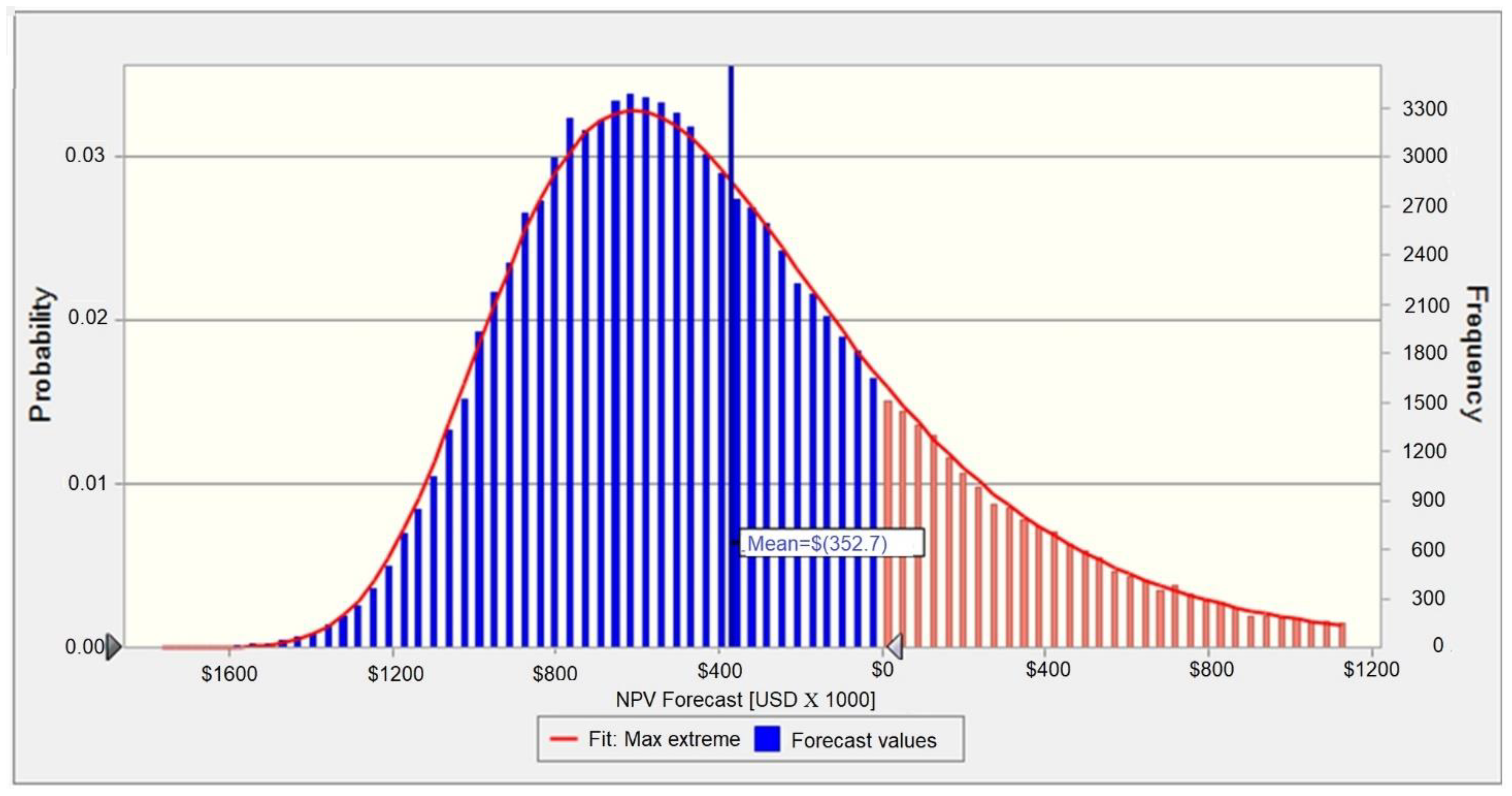
2.4. Economic Assessment

For the cases that presented technical applicability potential (syngas LHV ≥ 8 MJ/Nm3), their economic feasibility was determined based on the net present value (NPV) criterion. The United States dollar was used (USD 1.00 = BRL 5.72 in January 2022). The economic feasibility analysis of the system was complemented with a risk analysis using Monte Carlo simulations performed in Crystal Ball® software. The capital expenditure (CAPEX) of the gasification system was estimated according to the Capital Cost Scaling methodology [37], using the reference prices declared by [38,39]. Manufacturers were consulted regarding costs for gas microturbines and ASU.
The assumptions (variables with some degree of uncertainty) adopted during the risk study were:
  • The operation and maintenance costs of the gasification system, excluding biomass cost: range from 3.5 to 5.7% of the gasifier CAPEX [40]. In this study, the mean value (4.6%) was taken as the starting parameter, and during the risk study, the lower and upper limits were subsequently incorporated into the analysis;
  • The operation and maintenance costs of the gas microturbine were estimated at 0.019 USD/kWh from [41], with lower and upper limits of 0.018 and 0.020 USD/kWh during risk analysis, respectively;
  • The electricity price: the reference value for the pre-tax electricity price in the baseline case was 0.1614 USD/kWh (current price). The variation of this parameter was estimated from the local energy price adjustments historical distribution;
  • The biomass (wood pellets) price: the variation range of raw material prices was established from the survey of local prices. The baseline value for the biomass price was 126.37 USD/ton;
  • The net electrical power delivered: a variation of ±15% in the net electrical power delivered due to the operation regime itself was considered;
  • The total capital expenditure investment: it was assumed that a possible short-term local market transformation and fluctuations of ±15% in the international equipment prices could occur.
The minimum acceptable rate of return (MARR) of the system was associated with a weighted average capital cost (WACC) of the renewable energy company under the assumption of a capital structure whose liabilities are 60% equity and 40% debt. The WACC was determined using the capital asset pricing model (CAPM). In this sense, the estimated WACC was 10.32% APY. Once the amounts of investment, income, and expenses were known, the system’s cash flow was analyzed. The project’s risk of becoming unfeasible was determined from a Monte Carlo simulation with 100,000.00 trials and a 95% confidence level, considering the lower limit of the economic decision criterion (NPV ≥ 0).

3. Results

3.1. System Operating with Atmospheric Air as the Gasification Agent

Figure 4 shows the behavior of syngas composition and LHV as ER increases, where oxidation reactions are promoted by increased oxygen availability.
The gasification temperature is particularly relevant to the proposed system. Figure 5 presents the relationship between this variable, the cold gas efficiency (CGE), the syngas LHV, and the yield rate.
In addition to reaching a significant CO content, the syngas obtained from the thermochemical conversion process of wood pellets presented other compounds, such as H2 and CH4, which contribute to the increase in the syngas LHV. Thus, Figure 6 shows the profile of syngas volumetric composition obtained as a function of the gasification temperature.

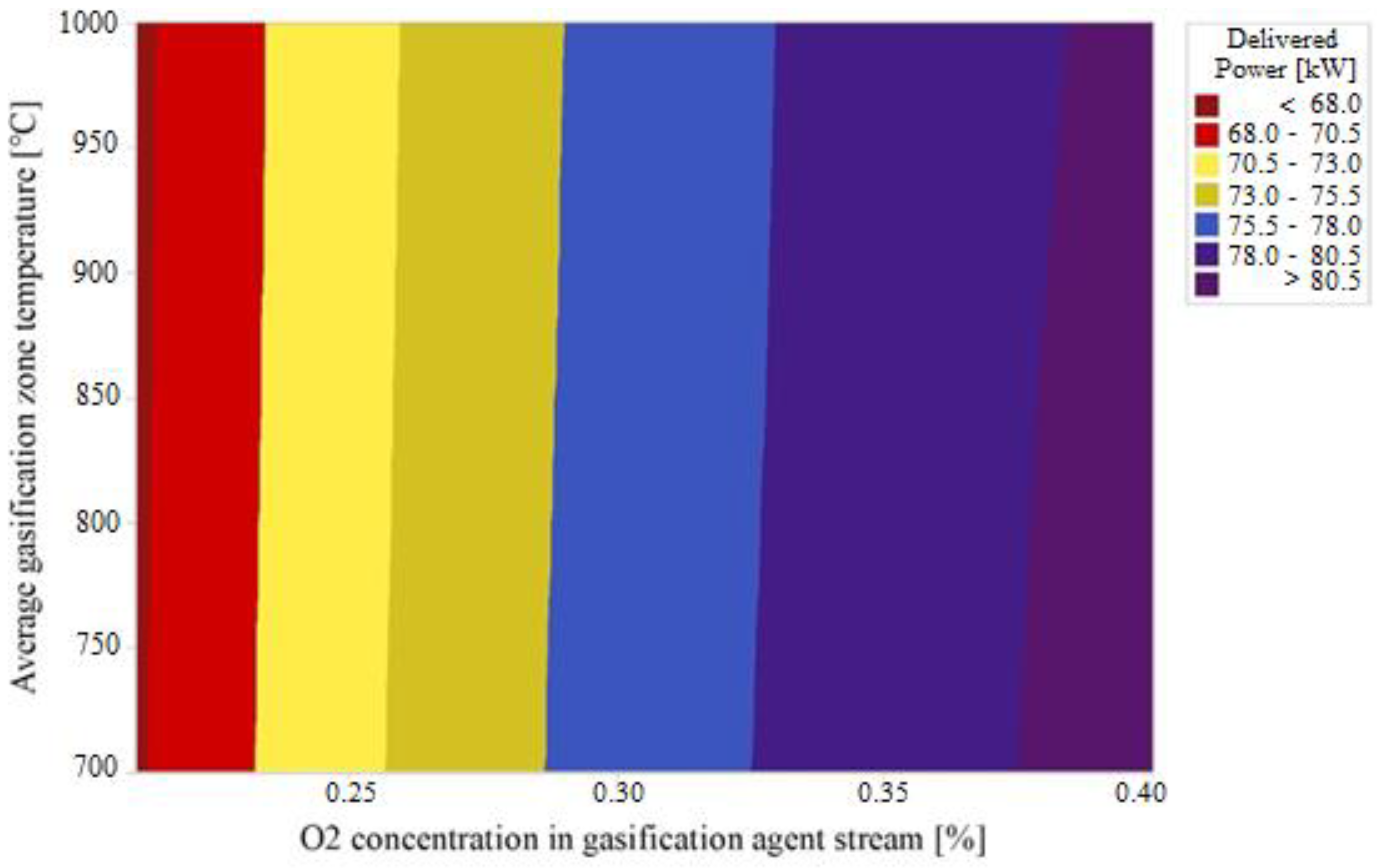
3.2. System Operating with Oxygen-Enriched Air as Gasification Agent

Figure 7 displays the influence of the oxygen concentration in the enriched air on the composition and LHV of syngas, while Figure 8 shows the effects of oxygen concentration in the gasification agent on CGE and syngas yield.
On the other hand, the behavior of CGE, LHV, and syngas yield for this scenario as a function of the average temperature in the gasification zone is shown in Figure 9. An additional analysis of gasification temperature and LHV syngas is presented in Supplementary Material B (Figure S3).
Due to the partial removal of nitrogen from atmospheric airflow supplied to the gasifier, a significant drop in the content of this compound is observed in the syngas (Figure 10). Figure 11 shows the variation of the power delivered as a function of the oxygen concentration of the enriched air and the average temperature in the gasification zone; both parameters significantly impact the engine performance.
The main economic parameters of the proposed system are described in Table 6, where it is possible to observe the investments necessary for its construction in a segregated form.
Since the components of the proposed system are not available in the domestic Brazilian market, it will be essential to bear the taxes presented in Table 7 for its importation. The annual revenues, represented by savings in electricity not purchased from the local utility company, are described in Table 8.
The annual operating, maintenance, and fuel (biomass) expenses for the gas microturbine and downdraft gasifier-based generation system are described in Table 9. Other relevant parameters used in the economic assessment are described in Table 10.
From the known data (discount rate, investment segregation, and expenses segregation) and the estimated annual savings resulting from implementing the gas microturbine and downdraft gasifier-based generation system, it was possible to establish the cash flow shown in Figure 12. Note that the initial investment of the host company was USD 708,592.24.
The forecasted statistical distribution for the project NPV and its Max Extreme fit are presented in Figure 13. As can be seen from Figure 14 and Figure 15, the NPV of the venture is highly dependent on the electricity price. The CAPEX, the net electric power delivered by the system, and the biomass cost have marginal effects on economic viability. In addition, the operating and maintenance costs have a negligible impact on the system’s economic viability. The benefit/cost ratio of the project is presented in Figure S4 of Supplementary Materials.

4. Discussion

Figure 4 shows that the volumetric nitrogen content in the syngas is quite expressive and increases rapidly with the ER increase. The LHV of syngas shows a strong dependence on carbon monoxide and hydrogen fractions; there is a remarkable decline in syngas LHV as the nitrogen fraction increases, as described by Oveisi et al. [44] for the wood chip gasification process.
Figure 5 indicates that the temperature increase favors the syngas yield rate, which is associated with the decomposition and reform of the compounds present in the fuel and, therefore, a greater amount of syngas per mass unit of biomass is produced [45]. This trend agrees with some studies [46,47,48], where the syngas yield increased as the temperature rose when using air as a gasification agent in the thermochemical conversion of biomass. Regarding syngas LHV, an increasing behavior is observed as the temperature is augmented, which can be explained by temperature influence on the reactions since higher temperatures favor the reforming and thermal cracking reactions of the heavier organic fractions contained in the fuel [49]. Thus, lighter hydrocarbons with lower energy are produced, but combustible gases, such as CO and H2, increase considerably, leading to higher syngas LHV. Considering the values of syngas LHV obtained in the air gasification scenario, it is possible to conclude that coupling the microturbine to the downdraft gasifier is technically unfeasible. Therefore, the economic analysis of this scenario was not performed.
It is worth noting that the CGE considers only the chemical energy available in the produced gas (chemical contribution of combustible gases, such as H2, CO, and CH4, among others) [50]. Therefore, an increasing trend was observed as temperature increased due to the favoring of oxidation reactions. In this way, the content of CO and H2 in the syngas improved the CGE values, rising from 62% to approximately 78%. On the other hand, Figure 6 showed that the fractions of H2 and CO increased; this result is associated with the shift and char hydrogenation reactions, since temperatures greater than 700 °C favor the formation of the reactants in equilibrium (Le’s Principle Châtelier) [33]. The other reactions that contribute to the formation of H2 and CO are char gasification and steam methane reforming. However, these last two reactions can be limited after 1000 °C due to the lack of CH4, the main reactant in reversible reduction reactions [51]. The volumetric fraction of CH4 decreased as gasification temperature increased, remaining at almost zero for temperatures above 925 °C because methane cracking occurs under these conditions [52].
Figure 7 indicates that when oxygen-enriched air is used as the gasification agent, there is a considerable increase in the syngas LHV as the oxygen concentration in the gasification agent rises. There is also a close relationship between the LHV and the concentration of CO and H2. The depreciation of nitrogen entering the gasifier with the gasification agent leads to a substantial drop in syngas nitrogen content [53].
On the other hand, Figure 8 shows that the volume of syngas produced decreases as the oxygen content in the enriched air increases, a fact already predicted given the partial removal of the nitrogen in the air [54]. CGE remains virtually unchanged with increasing the O2 content.
Figure 9 shows that the syngas yield rate increased as the temperature increased, but this increment is smaller when compared to the air gasification scenario. Therefore, it is evident that the N2 content in the oxidant greatly influences the syngas yield [55]. Considering that the N2 is a chemically inert compound, it will also be part of the syngas composition and, in the oxygen-enriched air gasification case, the N2 content is lower by the implementation of the ASU unit. The syngas LHV showed a decreasing trend as the temperature increased, where oxygen (in higher concentrations in the gasification agent) and nitrogen in the air favors the formation of CO2, and the dilution effect, respectively [56]. Therefore, the content of CH4 in the syngas decreases, affecting the LHV (8.64 to 8.01 MJ/Nm3). Additionally, a higher oxygen concentration in the gasification agent and the process temperature increase results in a reactor operation near to a combustion regime, contributing to the syngas chemical energy increase and improving the CGE [57].
Figure 10 shows that the fractions of CO and H2 increased as temperature was augmented, while the fraction of CH4 was practically null for temperatures higher than 750 °C. These earlier trends can be explained by the chemical reactions in the gasification process. Since the char gasification, steam methane reforming, and Boudouard reactions are endothermic, an increase in temperature will cause the reaction equilibrium to change from reactants to products according to Le Châtelier’s Principle [58]. Temperatures greater than 700 °C favor the formation of H2 and CO (from steam methane reforming reaction), since the CH4 formed in the char hydrogenation reaction at low temperatures is cracked [59].
Besides the necessity of using higher fuel flow rates in the gas microturbine, due to the low syngas LHV, the presence of CO and H2 in the combustible gases can lead to combustion instabilities, especially when the hydrogen content surpasses 40%, as reported by Page et al. [24]. These instabilities are related to the anchoring position and structure of the flame inside the combustor. Using an oxygen-enriched gasification agent allows one to obtain the minimum desired LVH (8 MJ/Nm3) with a hydrogen content of around 30%.
In terms of electrical power, when fed with syngas produced in the oxygen-enriched air gasification scenario, the gas microturbine can deliver between 68.53 and 82.71 kW (Figure 11). In the baseline case (ER = 0.30; O2 = 40%; T = 850 °C), the power produced by the microturbine was 81.24 kW, and its thermal efficiency was 21.35%. The electricity generation system proposed, i.e., the C200 microturbine coupled to the downdraft gasifier using oxygen-enriched air as a gasification agent (including auxiliary systems), has an overall efficiency of 11.82%.
It is worth noting that the economic assessment was conducted from the point of view of a customer whose electrical demand is equal to or superior to the capacity of the proposed generation systems. Hence, with the adoption of this arrangement, the customer will not purchase part of its demand (electricity) from the utility company, which, in economic terms, results in avoided costs. Considering both the discounted rate (WACC = 10.32% APY) and NPV behavior, it is possible to conclude that the investment is economically unviable.
From Figure 13, it could be observed that with an accuracy of 95%, it is possible to state that the probability of experiencing a financial loss (negative NPV) is 79.93%. The mean NPV is USD 352.7, while the NPV probability distribution adjustment standard deviation is USD 234.0. This result is reflected in Figure 15, where it is possible to observe that the project’s NPV is highly dependent on the utility’s energy tariff (91.4%), while the share of investment CAPEX, the cost of biomass, and the net electrical power delivered by the system have a low impact. Operation and maintenance costs have a negligible effect on the economic viability of this system variant. Therefore, it would be necessary to increase the current price of the electricity purchased from the electrical grid (0.1614 USD/kWh) by 1.63 times to make the proposed system economically feasible, considering all other constant parameters. The proposed system’s resulting installation cost is 8821.53 USD/kW.

5. Conclusions

This work presents the modeling and validation of a gas microturbine and downdraft gasifier system. The results indicate that when using atmospheric air, the system produced syngas with a maximum LHV of 6.10 MJ/Nm3, while with oxygen-enriched air, the LHV ranged from 8.64 to 8.01 MJ/Nm3. Therefore, the syngas LHV obtained using atmospheric air is very low to sustain the gas microturbine operation, while using oxygen-enriched air as the gasification agent, the LHV showed technic feasibility in some cases (LHV > 8.0 MJ/Nm3).
The use of syngas in the gas microturbine leads to decreases in microturbine efficiency from 33% (nominal condition) to 21.35%, while the net power generated ranged between 68.53 and 82.71 kW. It is worth noting that using oxygen-enriched air as the gasification agent results in a system’s overall efficiency of 11.82%.
However, from an economic point of view, the system is unfeasible due to the probability of a financial loss (negative NPV) of 79.93%, where biomass prices, electricity delivery, and capital investment play a secondary role in the system’s viability. From a hypothesis test, it would be necessary to have very high electricity prices (1.63 times higher than current) to justify the investment, making this system economically impractical nowadays. Therefore, based on the Monte Carlo simulation, it was possible to establish that the electricity price is crucial to enable the proposed system to be economically viable.

Supplementary Materials

The following supporting information can be downloaded at: https://0-www-mdpi-com.brum.beds.ac.uk/article/10.3390/pr10112377/s1, Figure S1: ASU used during downdraft gasifier feeding with oxygen-enriched air; Figure S2: Scheme for oxygen-enriched air gasification scenario; Figure S3: Syngas LHV as a function of both oxygen concentration in enriched air flow and gasification temperature; Figure S4: Benefit/Cost ratio.

Author Contributions

Conceptualization, N.C.H. and Y.C.S.; methodology, O.J.V. and N.C.H.; software, N.C.H. and Y.C.S.; validation, Y.C.S., N.C.H. and E.E.S.L.; formal analysis, D.M.Y.M. and O.J.V.; investigation, E.d.O.P. and E.E.S.L.; resources, J.S.N.H. and E.d.O.P.; data curation, O.H.A.J. and E.E.S.L.; writing—original draft preparation, N.C.H. and Y.C.S.; writing—review and editing, O.J.V., J.S.N.H. and O.H.A.J.; visualization, O.H.A.J.; supervision, E.d.O.P.; project administration, D.M.Y.M.; funding acquisition, E.E.S.L. and O.J.V. All authors have read and agreed to the published version of the manuscript.

Funding

The authors would like to acknowledge the financial support from the Coordination for the Improvement of Higher Education Personnel (CAPES), Brazilian Council for Scientific and Technological Development (CNPq) n° 307223/2017-5, n° 407531/2018-1, n° 311651/2018-6, the PRH of the National Agency for Petroleum, Natural Gas, and Biofuels (PRH-ANP n°51.1), the Research Supporting Foundation of Minas Gerais State (FAPEMIG), Federal University of Itajubá (UNIFEI), and the Federal University of Latin American Integration (UNILA).

Data Availability Statement

Not applicable.

Conflicts of Interest

The authors declare no conflict of interest.

Nomenclature

APYAnnual percentage yield
ASUAir separation unit
BMBoston–Mathias alpha function
CAPEXCapital expenditures
CAPMCapital asset pricing model
CGECold gas efficiency
COFINSContribution to social security financing
DCOALIGTNon-conventional compounds density
EREquivalence ratio
HCOALGENNon-conventional compounds enthalpy
IAPWS-95International association for the properties of water and steam method
ICMSTax on the movement of goods and services
IPITaxes over industrialized products
LHVLow heating value
MARRMinimum acceptable rate of return
NPVNet present value
ORCOrganic Rankine cycle
PISSocial integration program contribution
SOFCSolid oxide fuel cell
TECCommon external tariff
WACCWeighted average capital cost
AIR Air flow for air gasification scenario
AIR 1 Air flow for oxygen-enriched air gasification scenario
BIOMASS Biomass flow
ER Equivalence ratio
N 2 Split Removed nitrogen split fraction in ASU

References

  1. International Energy Agency. World Energy Outlook; International Energy Agency: Paris, France, 2016. [Google Scholar]
  2. Koirala, B.P.; Koliou, E.; Friege, J.; Hakvoort, R.A.; Herder, P.M. Energetic Communities for Community Energy: A Review of Key Issues and Trends Shaping Integrated Community Energy Systems. Renew. Sustain. Energy Rev. 2016, 56, 722–744. [Google Scholar] [CrossRef] [Green Version]
  3. Castillo Santiago, Y.; Martínez González, A.; Venturini, O.J.; Sphaier, L.A.; Ocampo Batlle, E.A. Energetic and Environmental Assessment of Oil Sludge Use in a Gasifier/Gas Microturbine System. Energy 2022, 244, 123103. [Google Scholar] [CrossRef]
  4. Marques, T.E.; Castillo Santiago, Y.; Renó, M.L.; Yepes Maya, D.M.; Sphaier, L.A.; Shi, Y.; Ratner, A. Environmental and Energetic Evaluation of Refuse-Derived Fuel Gasification for Electricity Generation. Processes 2021, 9, 2255. [Google Scholar] [CrossRef]
  5. Benini, E. Progress in Gas Turbine Performance, 1st ed.; Benini, E., Ed.; IntechOpen: London, UK, 2013; ISBN 978-953-51-1166-5. [Google Scholar]
  6. Fershalov, A.Y.; Fershalov, Y.Y.; Fershalov, M.Y. Principles of Designing Gas Microturbine Stages. Energy 2021, 218, 119488. [Google Scholar] [CrossRef]
  7. Henao, N.C.; Lora, E.E.S.; Maya, D.M.Y.; Venturini, O.J.; Franco, E.H.M. Technical Feasibility Study of 200 kW gas Microturbine Coupled to a Dual Fluidized Bed Gasifier. Biomass Bioenergy 2019, 130, 105369. [Google Scholar] [CrossRef]
  8. Konečná, E.; Teng, S.Y.; Máša, V. New Insights into the Potential of the Gas Microturbine in Microgrids and Industrial Applications. Renew. Sustain. Energy Rev. 2020, 134, 110078. [Google Scholar] [CrossRef]
  9. Amaro, J.; Mendiburu, A.Z.; de Carvalho, J.A. Thermodynamic Study of Syngas Combustion in Gas Microturbines with Regeneration Composed with Metallic and Ceramic Materials. Appl. Therm. Eng. 2019, 157, 113285. [Google Scholar] [CrossRef]
  10. Castillo Santiago, Y.; Martínez González, A.; Venturini, O.J.; Yepes Maya, D.M. Assessment of the Energy Recovery Potential of Oil Sludge through Gasification Aiming Electricity Generation. Energy 2021, 215, 119210. [Google Scholar] [CrossRef]
  11. Martínez González, A.; Silva Lora, E.E.; Escobar Palacio, J.C. Syngas Production from Oil Sludge Gasification and Its Potential Use in Power Generation Systems: An Energy and Exergy Analysis. Energy 2019, 169, 1175–1190. [Google Scholar] [CrossRef]
  12. Hanchate, N.; Ramani, S.; Mathpati, C.S.; Dalvi, V.H. Biomass Gasification Using Dual Fluidized Bed Gasification Systems: A Review. J. Clean. Prod. 2021, 280, 123148. [Google Scholar] [CrossRef]
  13. Antolini, D.; Ail, S.S.; Patuzzi, F.; Grigiante, M.; Baratieri, M. Experimental Investigations of Air-CO2 Biomass Gasification in Reversed Downdraft Gasifier. Fuel 2019, 253, 1473–1481. [Google Scholar] [CrossRef]
  14. Kan, X.; Zhou, D.; Yang, W.; Zhai, X.; Wang, C.-H. An Investigation on Utilization of Biogas and Syngas Produced from Biomass Waste in Premixed Spark Ignition Engine. Appl. Energy 2018, 212, 210–222. [Google Scholar] [CrossRef]
  15. Liu, L.; Huang, Y.; Cao, J.; Liu, C.; Dong, L.; Xu, L.; Zha, J. Experimental Study of Biomass Gasification with Oxygen-Enriched Air in Fluidized Bed Gasifier. Sci. Total Environ. 2018, 626, 423–433. [Google Scholar] [CrossRef] [PubMed]
  16. Wang, L.; Du, X.; Chen, J.; Wu, Z. Numerical Study on Characteristics of Biomass Oxygen Enriched Gasification in the New Gasifier on an Experimental Basis. Renew. Energy 2021, 179, 815–827. [Google Scholar] [CrossRef]
  17. Cui, X.; Song, G.; Yao, A.; Wang, H.; Wang, L.; Xiao, J. Technical and Economic Assessments of a Novel Biomass-to-Synthetic Natural Gas (SNG) Process Integrating O2-Enriched Air Gasification. Process Saf. Environ. Prot. 2021, 156, 417–428. [Google Scholar] [CrossRef]
  18. Chuah, C.Y.; Muhammad Anwar, S.N.B.; Weerachanchai, P.; Bae, T.-H.; Goh, K.; Wang, R. Scaling-up Defect-Free Asymmetric Hollow Fiber Membranes to Produce Oxygen-Enriched Gas for Integration into Municipal Solid Waste Gasification Process. J. Membr. Sci. 2021, 640, 119787. [Google Scholar] [CrossRef]
  19. Sittisun, P.; Tippayawong, N.; Pang, S. Biomass Gasification in a Fixed Bed Downdraft Reactor with Oxygen Enriched Air: A Modified Equilibrium Modeling Study. Energy Procedia 2019, 160, 317–323. [Google Scholar] [CrossRef]
  20. Cao, Y.; Wang, Q.; Du, J.; Chen, J. Oxygen-Enriched Air Gasification of Biomass Materials for High-Quality Syngas Production. Energy Convers. Manag. 2019, 199, 111628. [Google Scholar] [CrossRef]
  21. Gu, H.; Tang, Y.; Yao, J.; Chen, F. Study on Biomass Gasification under Various Operating Conditions. J. Energy Inst. 2019, 92, 1329–1336. [Google Scholar] [CrossRef]
  22. Kolanowski, B.F. Guide to Microturbines, 1st ed.; Kolanowski, B.F., Ed.; Fairmont Press: Lilburn, GA, USA, 2004; ISBN 9780824740016. [Google Scholar]
  23. Rabou, L.P.L.M.; Grift, J.M.; Conradie, R.E.; Fransen, S. Micro Gas Turbine Operation with Biomass Producer Gas and Mixtures of Biomass Producer Gas and Natural Gas. Energy Fuels 2008, 22, 1944–1948. [Google Scholar] [CrossRef]
  24. Page, D.; Shaffer, B.; McDonell, V. Establishing Operating Limits in a Commercial Lean Premixed Combustor Operating on Synthesis Gas Pertaining to Flashback and Blowout. In Proceedings of the ASME Turbo Expo 2012: Turbine Technical Conference and Exposition, Copenhagen, Denmark, 11–15 June 2012; pp. 647–656. [Google Scholar]
  25. Moradi, R.; Marcantonio, V.; Cioccolanti, L.; Bocci, E. Integrating Biomass Gasification with a Steam-Injected Micro Gas Turbine and an Organic Rankine Cycle Unit for Combined Heat and Power Production. Energy Convers. Manag. 2020, 205, 112464. [Google Scholar] [CrossRef]
  26. Perna, A.; Minutillo, M.; Jannelli, E.; Cigolotti, V.; Nam, S.W.; Yoon, K.J. Performance Assessment of a Hybrid SOFC/MGT Cogeneration Power Plant Fed by Syngas from a Biomass Down-Draft Gasifier. Appl. Energy 2018, 227, 80–91. [Google Scholar] [CrossRef]
  27. Renzi, M.; Patuzzi, F.; Baratieri, M. Syngas Feed of Micro Gas Turbines with Steam Injection: Effects on Performance, Combustion and Pollutants Formation. Appl. Energy 2017, 206, 697–707. [Google Scholar] [CrossRef]
  28. Corrêa, P.S.P.; Zhang, J.; Lora, E.E.S.; Andrade, R.V.; de Mello e Pinto, L.R.; Ratner, A. Experimental Study on Applying Biomass-Derived Syngas in a Microturbine. Appl. Therm. Eng. 2019, 146, 328–337. [Google Scholar] [CrossRef]
  29. Aghaalikhani, A.; Schmid, J.C.; Borello, D.; Fuchs, J.; Benedikt, F.; Rispoli, F.; Henriksen, U.B.; Sárossy, Z.; Cedola, L. Detailed Modelling of Biomass Steam Gasification in a Dual Fluidized Bed Gasifier with Temperature Variation. Renew. Energy 2019, 143, 703–718. [Google Scholar] [CrossRef]
  30. Basu, P. Biomass Gasification, Pyrolysis, and Torrefaction: Practical Design and Theory, 2nd ed.; Basu, P., Ed.; Elsevier Inc.: San Diego, CA, USA, 2013; ISBN 978-0-12-396488-5. [Google Scholar]
  31. Belaissaoui, B.; le Moullec, Y.; Hagi, H.; Favre, E. Energy Efficiency of Oxygen Enriched Air Production Technologies: Cryogeny vs Membranes. Sep. Purif. Technol. 2014, 125, 142–150. [Google Scholar] [CrossRef]
  32. Zainal, Z.A.; Ali, R.; Lean, C.H.; Seetharamu, K.N. Prediction of Performance of a Downdraft Gasifier Using Equilibrium Modeling for Different Biomass Materials. Energy Convers. Manag. 2001, 42, 1499–1515. [Google Scholar] [CrossRef]
  33. Han, J.; Liang, Y.; Hu, J.; Qin, L.; Street, J.; Lu, Y.; Yu, F. Modeling Downdraft Biomass Gasification Process by Restricting Chemical Reaction Equilibrium with Aspen Plus. Energy Convers. Manag. 2017, 153, 641–648. [Google Scholar] [CrossRef]
  34. Capstone. Capstone MicroTurbine® Fuel Requirements Technical Reference; Capstone: Chatsworth, CA, USA, 2014. [Google Scholar]
  35. Capstone. Capstone C200 Microturbine Technical Reference; Capstone: Los Angeles, CA, USA, 2009. [Google Scholar]
  36. Gagliano, A.; Nocera, F.; Bruno, M.; Cardillo, G. Development of an Equilibrium-Based Model of Gasification of Biomass by Aspen Plus. Energy Procedia 2017, 111, 1010–1019. [Google Scholar] [CrossRef]
  37. Turner, M.J.; Pinkerton, L.L. Quality Guidelines for Energy System Studies: Capital Cost Scaling Methodology; National Energy Technology Laboratory (NETL): Pittsburgh, PA, USA, 2013.
  38. Holmgren, K.M. Investment Cost Estimates for Gasificationbased Biofuel Production Systems; IVL Swedish Environmental Research Institute: Stockholm, Sweden, 2015. [Google Scholar]
  39. Food and Agriculture Organization (FAO). Bioenergy and Food Security Rapid Appraisal: User Manual; FAO: Rome, Italy, 2014. [Google Scholar]
  40. Watson, J.; Zhang, Y.; Si, B.; Chen, W.-T.; de Souza, R. Gasification of Biowaste: A Critical Review and Outlooks. Renew. Sustain. Energy Rev. 2018, 83, 1–17. [Google Scholar] [CrossRef]
  41. Davidson, K.; Hite, R.; Jones, D.; Howley, A. A Comprehensive Assessment of Small Combined Heat and Power Technical and Market Potential in California; California Energy Commission: Sacramento, CA, USA, 2019.
  42. Ferrara, M.; Chiang, Y.-M.; Deutch, J.M. Demonstrating Near-Carbon-Free Electricity Generation from Renewables and Storage. Joule 2019, 3, 2585–2588. [Google Scholar] [CrossRef]
  43. Craig, K.R.; Mann, M.K. Cost and Performance Analysis of Biomass-Based Integrated Gasification Combined-Cycle (BIGCC) Power Systems; National Renewable Energy Laboratory (NREL): Golden, CO, USA, 1996.
  44. Oveisi, E.; Sokhansanj, S.; Lau, A.; Lim, J.; Bi, X.; Preto, F.; Mui, C. Characterization of Recycled Wood Chips, Syngas Yield, and Tar Formation in an Industrial Updraft Gasifier. Environments 2018, 5, 84. [Google Scholar] [CrossRef] [Green Version]
  45. Kook, J.W.; Choi, H.M.; Kim, B.H.; Ra, H.W.; Yoon, S.J.; Mun, T.Y.; Kim, J.H.; Kim, Y.K.; Lee, J.G.; Seo, M.W. Gasification and Tar Removal Characteristics of Rice Husk in a Bubbling Fluidized Bed Reactor. Fuel 2016, 181, 942–950. [Google Scholar] [CrossRef]
  46. Pandey, A.; Bhaskar, T.; Stöcker, M.; Sukumaran, R.K.B.T. Recent Advances in Thermochemical Conversion of Biomass; Elsevier: Boston, MA, USA, 2015; ISBN 978-0-444-63289-0. [Google Scholar]
  47. Upadhyay, D.S.; Sakhiya, A.K.; Panchal, K.; Patel, A.H.; Patel, R.N. Effect of Equivalence Ratio on the Performance of the Downdraft Gasifier—An Experimental and Modelling Approach. Energy 2019, 168, 833–846. [Google Scholar] [CrossRef]
  48. Mun, T.-Y.; Kim, J.-O.; Kim, J.-W.; Kim, J.-S. Influence of Operation Conditions and Additives on the Development of Producer Gas and Tar Reduction in Air Gasification of Construction Woody Wastes Using a Two-Stage Gasifier. Bioresour. Technol. 2011, 102, 7196–7203. [Google Scholar] [CrossRef] [PubMed]
  49. Martínez González, A.; Lesme Jaén, R.; Silva Lora, E.E. Thermodynamic Assessment of the Integrated Gasification-Power Plant Operating in the Sawmill Industry: An Energy and Exergy Analysis. Renew. Energy 2020, 147, 1151–1163. [Google Scholar] [CrossRef]
  50. Martínez González, A.; Silva Lora, E.E.; Escobar Palacio, J.C.; Almazán del Olmo, O.A. Hydrogen Production from Oil Sludge Gasification/Biomass Mixtures and Potential Use in Hydrotreatment Processes. Int. J. Hydrogen Energy 2018, 43, 7808–7822. [Google Scholar] [CrossRef]
  51. Lan, W.; Chen, G.; Zhu, X.; Wang, X.; Wang, X.; Xu, B. Research on the Characteristics of Biomass Gasification in a Fluidized Bed. J. Energy Inst. 2019, 92, 613–620. [Google Scholar] [CrossRef]
  52. Bizkarra, K.; Barrio, V.L.; Arias, P.L.; Cambra, J.F. Biomass Fast Pyrolysis for Hydrogen Production from Bio-Oil. In Hydrogen Production Technologies; Sankir, M., Sankiri, N.D., Eds.; John Wiley & Sons: Hoboken, NJ, USA, 2017; pp. 305–362. ISBN 9781119283676. [Google Scholar]
  53. Sharma, T.; Maya, D.M.Y.; Nascimento, F.R.M.; Shi, Y.; Ratner, A.; Silva Lora, E.E.; Neto, L.J.M.; Palacios, J.C.E.; Andrade, R.V. An Experimental and Theoretical Study of the Gasification of Miscanthus Briquettes in a Double-Stage Downdraft Gasifier: Syngas, Tar, and Biochar Characterization. Energies 2018, 11, 3225. [Google Scholar] [CrossRef] [Green Version]
  54. Khosasaeng, T.; Suntivarakorn, R. Effect of Equivalence Ratio on an Efficiency of Single Throat Downdraft Gasifier Using RDF from Municipal Solid Waste. Energy Procedia 2017, 138, 784–788. [Google Scholar] [CrossRef]
  55. Kuo, P.C.; Wu, W.; Chen, W.H. Gasification Performances of Raw and Torrefied Biomass in a Downdraft Fixed Bed Gasifier Using Thermodynamic Analysis. Fuel 2014, 117, 1231–1241. [Google Scholar] [CrossRef]
  56. Sharma, P.; Gupta, B.; Pandey, M.; Singh Bisen, K.; Baredar, P. Downdraft Biomass Gasification: A Review on Concepts, Designs Analysis, Modelling and Recent Advances. Mater. Today Proc. 2021, 46, 5333–5341. [Google Scholar] [CrossRef]
  57. Castillo Santiago, Y.; Pérez, J.F.; Sphaier, L.A. Reaction-Front and Char Characterization from a Palm Kernel Shell—Oil Sludge Mixture under Oxygen Lean Regimes in a Fixed-Bed Gasifier. Fuel 2023, 333, 126402. [Google Scholar] [CrossRef]
  58. Liu, Z.; Zhao, C.; Cai, L.; Long, X. Steady State Modelling of Steam-Gasification of Biomass for H2-Rich Syngas Production. Energy 2022, 238, 121616. [Google Scholar] [CrossRef]
  59. Jaffar, M.M.; Nahil, M.A.; Williams, P.T. Synthetic Natural Gas Production from the Three Stage (i) Pyrolysis (Ii) Catalytic Steam Reforming (Iii) Catalytic Hydrogenation of Waste Biomass. Fuel Process. Technol. 2020, 208, 106515. [Google Scholar] [CrossRef]
Figure 1. Methodology scheme.
Processes 10 02377 g001
Figure 2. Downdraft Gasifier Model.
Processes 10 02377 g002
Figure 3. Gas microturbine scheme.
Processes 10 02377 g003
Figure 4. Composition and LHV behavior of the syngas as a function of airflow and ER.
Processes 10 02377 g004
Figure 5. Cold gas efficiency, LHV, and syngas yield as a function of gasification temperature.
Processes 10 02377 g005
Figure 6. Syngas composition as a function of gasification temperature.
Processes 10 02377 g006
Figure 7. Composition and LHV of syngas as a function of oxygen concentration in the gasification agent.
Processes 10 02377 g007
Figure 8. Cold gas efficiency and syngas yield rate as a function of oxygen concentration in the gasification agent.
Processes 10 02377 g008
Figure 9. CGE, LHV, and yield rate behavior of syngas as a function of gasification temperature when using oxygen-enriched air (O2 = 40%).
Processes 10 02377 g009
Figure 10. Syngas composition as a function of the gasification temperature when using enriched air (O2 = 40%).
Processes 10 02377 g010
Figure 11. Power delivered by gas microturbine as a function of both the gasification temperature and the oxygen content in enriched air.
Processes 10 02377 g011
Figure 12. Cash flow from the gas microturbine and downdraft gasifier-based generation system using oxygen-enriched air as a gasification agent.
Processes 10 02377 g012
Figure 13. NPV forecast of the gas microturbine and downdraft gasifier-based generation system using oxygen-enriched air as a gasification agent.
Processes 10 02377 g013
Figure 14. Assumptions scatter plot for the Monte Carlo simulation considering the NPV as a target in the gas microturbine and downdraft gasifier-based generation system.
Processes 10 02377 g014
Figure 15. Assumptions contribution to NPV variation in the gas microturbine and downdraft gasifier-based generation system using oxygen-enriched air as a gasification agent.
Processes 10 02377 g015
Table 1. Ultimate and proximate analysis of fuel used [29].
Ultimate AnalysisProximate Analysis
ComponentContent [%]ComponentContent [%]
Carbon50.70Volatiles (Dry Basis)85.40
Hydrogen5.90Fixed Carbon (Dry Basis)14.40
Oxygen43.00Ash (Dry Basis)0.20
Nitrogen0.19Moisture (Wet Basis)7.20
Sulfur5 × 10−3
Chlorine5 × 10−3
Ash0.20
Table 2. Reactions in the gasification process.
CodeChemical ReactionReaction NameReaction Heat (kJ/mol)Zone
R1Biomass → volatiles + charBiomass pyrolysis-PYZON
R2H2+ 1/2O2 → H2OHydrogen oxidation−242COMBUZON
R3CO + 1/2O2 → CO2Monoxide carbon oxidation−238COMBUZON
R4C + 1/2O2 → COPartial oxidation of char−111COMBUZON
R5C + O2 → CO2Total oxidation of char−394COMBUZON
R6C + CO2 ←→ 2COBoudouard reaction+172REDUZON
R7CO + H2O ←→ CO2 + H2Shift reaction−41REDUZON
R8C + H2O ←→ CO + H2Char gasification+131REDUZON
R9C + 2H2 ←→ CH4Char hydrogenation−75REDUZON
R10CH4 + H2O ←→ CO + 3H2Steam methane reforming+206REDUZON
Table 3. Oxygen concentration in AGENT flow and nitrogen fractions removed in ASU block.
Oxygen Volumetric
Concentration in AGENT Flow [%]
Nitrogen Volumetric
Concentration in AGENT Flow
[%]
Removed Nitrogen Flow
[kg/h]
Removed Nitrogen Split Fraction at ASU Block
[-]
217900
257525.260.2025
307047.370.3797
356563.160.5063
406075.010.6013
Table 4. Validation of the downdraft gasifier model results.
ParameterUnitsValues
Average gasification zone temperature°C850850800800
Equivalence ratio[-]0.360.360.270.27
BiomassN/AWood chipWood ChipWood PelletsWood Pellets
Low heating valueMJ/Nm34.854.705.145.52
Composition
H2%15.2316.3918.3221.37
CO%23.0420.9120.9319.29
CO2%16.4217.1612.8711.72
CH4%1.580.83.092.2
N2%42.3144.5444.7945.42
Other species%1.420.2--
SourceN/A[32]This model[33]This model
RMSN/A-1.49-1.55
Table 5. Capstone C200 microturbine datasheet [35].
ParameterValue
Rating200 kW
Electrical Efficiency33%
Net Heat Rate LHV10.9 MJ/kWh
Exhaust Gas Flow1.3 kg/s
Compression ratio4.0
Table 6. Investment required to construct the downdraft gasifier/gas microturbine system using oxygen-enriched air as the gasification agent.
Feature/ItemUnit of MeasureMagnitude
Electric powerkW81.35
Availability factor [42]%95
Annual energykWh/Year676,994.70
Investment
Gas microturbineUSD347,600.00
Downdraft gasifier
(Includes installation)
USD92,939.61
Air separation unitUSD8640.00
Canvas gasometerUSD5001.00
Balance of plant (BOP) [43]USD88,107.92
Import taxesUSD166,303.70
TotalUSD708,592.24
Table 7. Taxes on equipment imports in the Brazilian state of Minas Gerais.
TaxMagnitude
TEC Mercosur0.00%
IPI8.00%
PIS2.10%
COFINS9.65%
ICMS (Minas Gerais)18.00%
Total37.75%
Table 8. Annual revenue from the gas microturbine and downdraft gasifier-based generation system using oxygen-enriched air as a gasification agent.
ParameterUnit Magnitude
Electricity price (before tax)USD/kWh0.1614
Electricity taxes
(Resolution 2550/2019)
%25.00
Electricity price (After tax)USD/kWh0.2017
Annual revenueUSD/Year136,583.68
Table 9. Annual costs for the gas microturbine and downdraft gasifier-based generation system using oxygen-enriched air as a gasification agent.
Annual ExpensesUnit Magnitude
Gas microturbine operation and maintenance (O&M)USD12,725.57
Downdraft gasifier operation and maintenance (O&M)USD4275.22
Wood pelletsUSD102,956.65
TotalUSD119,957.44
Table 10. Complementary data for the economic feasibility assessment of the gas microturbine and downdraft gasifier-based generation system using oxygen-enriched air as a gasification agent.
ParameterUnit Magnitude
Service lifeYears15.00
Brazilian Real/United States Dollar exchange rateBRL/USD5.72
Income tax 1%0.00
Depreciation% APY10.00
MARR% APY10.32
Wood pellets priceUSD/ton126.37
1 This does not apply because it is a saving, not revenue itself.
Publisher’s Note: MDPI stays neutral with regard to jurisdictional claims in published maps and institutional affiliations.

