
Pilot-Scale Experimental Study of a New High-Loading Absorbent for Capturing CO2 from Flue Gas

1
National Institute of Clean-and-Low-Carbon Energy, Beijing 102211, China
2
State Key Laboratory of Chemical Engineering, Tsinghua University, Beijing 100084, China
3
State Key Laboratory of Clean Energy Utilization, Zhejiang University, Hangzhou 310027, China
*
Author to whom correspondence should be addressed.
Processes 2022, 10(3), 599; https://0-doi-org.brum.beds.ac.uk/10.3390/pr10030599
Submission received: 21 January 2022
/
Revised: 3 March 2022
/
Accepted: 4 March 2022
/
Published: 19 March 2022
(This article belongs to the Topic Carbon Capture, Storage and Utilisation Technologies (CCS/CCU))
Abstract
:Chemical absorbents with low-energy requirements have become the primary focus of the research on CO2 capture from flue gas in power plants. To verify the absorption performance of the NICE absorbent developed by the National Institute of Clean-and-Low-Carbon Energy in China, a performance optimization test was conducted in Zhejiang University’s pilot-scale platform, and the effects of the liquid–gas ratio, regeneration pressure, rich liquid fractional flow, and interstage cooling on the absorption performance and regeneration energy consumption were investigated. The results showed that in the CO2 pilot test, the optimized minimum regeneration energy consumption was 2.85 GJ/t CO2, and the corresponding process parameters were as follows: a liquid–gas ratio of 1.82 L/m3, regeneration pressure of 191 kPa, an interstage cooling temperature of 40 °C, and a rich liquid fractional flow ratio of 0.18. This study preliminarily verified the low-energy consumption performance of the NICE absorbent and showed its good potential for industrial applications. Additionally, the NICE absorbent showed promise for capital and operating cost savings because of its low liquid–gas ratio.
1. Introduction
Currently, carbon neutrality is China’s national strategy. According to the prediction made by the Intergovernmental Panel on Climate Change (IPCC), the contribution of carbon capture, utilization, and storage (CCUS) technology will reach 14% in 2050 if the mean global temperature increases by more than 2 °C [1]. CCUS technology is essential for achieving carbon neutrality in China, and its application range will be considerably broad. Among many CO2 capture technologies, the post-combustion chemical absorption technology is one of the technical routes with the highest potential for large-scale CO2 capture, owing to its good flue gas adaptability, high capture efficiency, and relatively mature technology [2,3,4,5]. Currently, most carbon capture devices worldwide adopt chemical absorption technology.
Amine-based solvents, such as monoethanolamine (MEA), are commonly used for absorption processes. Due to its high absorption rate, large CO2 capacity, low viscosity, and high chemical/thermal stability, MEA is used widely; however, its energy consumption for regeneration is as high as 4.0 GJ/t CO2 [6], accounting for 60–80% of the total energy consumption [7,8]. Therefore, the development of organic amine absorbents with low regeneration energy requirements has become the focus of research. In laboratory studies, blended amine solvents [9,10], water-lean solvents [11,12], ionic liquids [13,14], amino acid salts [15], and biphasic solvents [16,17,18] have been investigated to reduce the regeneration energy consumption for CO2 capture. In this regard, significant progress has been achieved. The regeneration energy consumption of the 2-amino-2-methyl-1-propanol based non-aqueous absorbent has been shown to be 2.1 GJ/t CO2 [19]. The regeneration energy consumptions of alkanolamine biphasic absorbents has been shown to reduce to 2.6 GJ/t CO2 [20]. The regeneration energy consumption of the MEA-sulfolane biphasic absorbent has been shown to successfully reduce to 1.8 GJ/t CO2 [21]. However, the rapid increase in viscosity during CO2 absorption using such absorbents deteriorates mass transfer and liquid transportation, which are crucial for industrial applications [22]. High capital and operating expenses also limit their industrial applications.
While there are many laboratory-scale studies on these absorbents, there are few studies on their industrial-scale feasibility, and most pilot plant studies have focused on amine-based absorbents. The regeneration energy consumed during the 100,000 tons/year Piperazine absorber demonstration carried out by the Alabama Carbon Capture Center was as low as 2.6 GJ/t CO2 [23]. The regeneration energy of the amine solution, which was tested at the 0.7 MWe CO2 capture facility at Kentucky Utilities, was in the range of 2.9–3.3 GJ/t CO2 [24]. The 150,000 tons/year demonstrative regeneration of mixed amine absorbent carried out by China’s Jinjie Power Plant consumes 2.4 GJ/t CO2 [25]. These pilot plant studies are necessary to evaluate absorbents under practical conditions to bridge the existing knowledge gaps. However, these absorbents with low regeneration energy requirements function based on low reaction heat and have a relatively high liquid–gas ratio, ranging from 2.55 to 4.80 L/m3 [23,24,25,26]. An absorbent with a high CO2 absorption capacity resulting in a low liquid–gas ratio (<1.9 L/m3) has been scarcely studied. The high-capacity absorbent just requires a low solvent flow rate in the circulating system, and the operating and equipment costs can be reduced. However, the quantifiable strengths and weaknesses of high-capacity absorbents is still unclear. On the other hand, many over 1,000,000 tons/year CO2 absorption capacity facilities with amine solution will be built in China. As a result, a pilot-scale study on high-capacity absorbents is necessary to investigate whether high-capacity absorbent has good potential for industrial applications. It is also necessary to study whether the current absorption equipment is suitable for high-capacity absorbents. Furthermore, these absorbents are still expensive in China, selling at prices more than 60,000 CNY/t. The development of novel absorbents with low production and operating expenses remains a major challenge.
In this paper, the NICE absorbent developed and named by the National Institute of Clean-and-Low-Carbon Energy (NICE) in China showed an improved CO2 absorption capacity, a low liquid–gas ratio, and a low regeneration energy. Compared to MEA, the NICE absorbent exhibits lower corrosion rates, solvent degradation rates, and amine loss [27]. In this work, the NICE absorbent was tested to determine if it can exhibit its best performance in traditional MEA absorption system. Through this pilot test, the regeneration energy consumption of the absorbent was investigated. The optimal operating parameters of the absorbent were obtained and compared to those of the MEA from previous tests, including the liquid–gas ratio, regeneration pressure, rich liquid fractional flow, and interstage cooling, in relation to their effects on the absorption performance of the absorbent. While there is a major focus on saving cost in producing the NICE absorbent, compared to the case with MEA, the actual operation properties of the NICE absorbent also determine the design of the corresponding new capture system.
2. Methods
2.1. Experimental Device
The pilot-scale test platform was built at the Thermal Energy Institute at the Zhejiang University. The process flowchart and elevation layout of the platform are shown in Figure 1 and Figure 2, respectively. The test platform was divided into six layers with a total height of 16.2 m. The whole system includes five towers: absorption I, absorption II, stripper, pretreatment, and water-washing.
The flue gas treatment capacity of the system is 200–300 Nm3/h. An oil-fired boiler flue gas is employed with a CO2 dry base concentration of 10–12%. The heat required for regeneration is also derived from the oil-fired boiler steam.
2.2. Experimental Process Flow
The experimental process flow involves several steps. The flue gas from the outlet of the oil-fired boiler is pre-treated by an alkali scrubber and subsequently decarburized by an absorption tower. The flue gas enters the absorption tower from the bottom of the absorption tower and encounters the absorption liquid in reverse. The absorbent absorbs CO2 in the flue gas, and stays in the absorption tower about 2~3 min. The interstage cooling process reduces the reaction temperature and improves the absorption efficiency. After decarbonization, the flue gas is cooled by the washing tower and the loaded absorbent in the flue gas is eluted simultaneously; thereafter, it is finally discharged into the atmosphere.
After absorbing CO2, the rich liquid exits the absorption tower through the pump at the bottom of the tower. A portion of the rich liquid is sent to the plate heat exchanger to absorb the heat of the lean liquid, after which it is sent to the regeneration tower. Another portion of the rich liquid is directly sent to the top of the regeneration tower to condense the water vapor in the regeneration gas and recover the regeneration heat. The desorption of the absorbent lean liquid in the regeneration tower occurs with cooling by the liquid heat exchanger and the lean liquid cooler; thereafter, it returns to the absorbent tower to complete the absorption cycle.
The regeneration gas desorbed from the top of the regeneration tower is cooled to obtain the product gas, CO2, and the condensate water of the regeneration gas is returned to the regeneration tower.
Once changing the process conditions, the platform needs to run for 3 h to achieve a steady state. In this experiment, samples were obtained at 30 min intervals. The data points were obtained by sampling five times on average.
2.3. Test Method
2.3.1. Gas Component Analysis
The inlet flue gas, outlet flue gas, and regenerated product gas of the absorption tower were fed into the Beijing Huayun portable infrared analyzer (Beijing Huayun Analytical Instrument Research Institute Co. LTD, Beijing, China) through a drying pipe to analyze the CO2 concentration. The instrument model used was GXH-3011E; instrument ranges were 0–5%, 0–15%, and 0–100%; the inlet volumetric flow rate was 0.9 L/min; measurement linearity was ≤±2% F.S; and reproducibility was ≤±1% F.S. Before the test, standard gas was used to calibrate the measurement accuracy.
2.3.2. Amine Solution Concentration Test
The amine concentration was measured by an acid–base neutralization reaction. An aqueous solution of organic amine presents weak alkalinity, owing to the hydrolysis reaction. In the acid–base neutralization reaction, with the continuous addition of the acid, the pH and potential in the solution changed. The concentration of the amine solution was calculated by adding the amount of acid and measuring the potential of the solution. The calculation formula used is as follows [28]:
where C is the amine solution concentration (mol/L), Vs is the volume of the sample (μL), CH+ is the concentration of acid used for titration (mol/L), and VH+ is the volume of acid (mL). Before the test, the standard solution was used to calibrate the measurement accuracy, which was less than 1%.
2.3.3. CO2 Loading Test
As shown in Figure 3, the sealing fluid was poured into a level bottle. Thereafter, 400 μL of an amine solution was injected into the small isolation flask of the carbon dioxide reaction bottle. Subsequently, 2 mL of an H2SO4 solution was added to the outside of the isolation flask, the clock was rotated to the tee position, and the level bottle was raised so that the liquid level set in the measuring pipe reached the top mark. Afterward, we rotated the cock until the gas cylinder was only connected to the CO2 reaction bottle, after which we placed the level bottle down to determine the system’s airtightness. After determining that there were no leakage issues, the reaction bottle was tilted, and the amine solution was in good contact with sulfuric acid. The reaction bottle was shaken vigorously until the liquid level of the pipe remained constant. Thereafter, the level bottle was raised closer to the pipe, and the two liquid levels were positioned in parallel. The volume (V), temperature (t), and atmospheric pressure (P) were read, and the CO2 loading of the amine solution was calculated.
2.3.4. Regeneration Energy Consumption Calculation
The regeneration energy consumption is an important index for evaluating the cycle characteristics of absorbents and the operation cost in industrial applications. The calculation of the regeneration energy consumption is based on the amount of CO2 produced and steam consumption, and is calculated using the following formula [29]:
where W is the regeneration energy consumption, GJ/t CO2; QSTEAM is the mass flow rate of steam in the reboiler, t/h; QCO2 is the mass flow rate of CO2 in the regeneration gas, t/h; H is the enthalpy of water vapor, GJ/t, H′ is the enthalpy of condensate water, GJ/t. The steam mass flow rate was directly measured using a steam flowmeter. The mass flow rate of the regeneration gas was further calculated considering the temperature and pressure by the following formula [30]:
where VCO2 is the volumetric flow rate of the regenerated CO2 in the standard state, m3/h; P′CO2 is the regeneration pressure, kPa; PCO2 is the standard atmospheric pressure, kPa; T′CO2 is the regeneration temperature, K; TCO2 is room temperature, K; is the density of CO2 in the standard state, t/m3.
3. Results and Discussion
3.1. The Effect of the Liquid–Gas Ratio
The liquid–gas ratio is an important parameter in the solvent absorption process, which directly affects the working efficiency of the absorption tower, material transport, and regeneration energy consumption. In the test, the flue gas flow rate was maintained at a maximum value of 275 m3/h, the steam consumption was maintained at 75 kg/h, the regeneration pressure was 101.3 kPa, the difference between the rich and lean liquid outlets of the heat exchanger was 3.5 K, the interstage cooling temperature was 40 °C, the rich liquid fractional flow ratio was 0, the solution flow range was 400–1000 L/h, and the corresponding liquid–gas ratio was 1.45–3.64 L/m3.
The CO2 loadings of the lean and rich liquids in stable operation, at different liquid–gas ratios are shown in Figure 4. With the liquid–gas ratio increasing from 1.45 to 3.64 L/m3, the CO2 loadings of the lean liquid increased by 94%, loadings of the rich liquid decreased by 8%, and the circulating loadings decreased by 64%. The lean liquid is the outlet solution of the regeneration tower, and its load quantity represents the situation of the regeneration process of the solution. The higher the load quantity, the lower the regeneration efficiency, which is the ratio of regenerated solution to rich liquid. With a fixed steam amount, the higher the liquid–gas ratio, the higher the amount of the solution that needs to be heated per unit time and the lower the regeneration efficiency. The rich liquid is the outlet solution of the absorption tower, and its load represents the situation of the absorption process of the solution. The higher the load amount, the higher the absorption efficiency of the solution. At a constant flue gas flow, the smaller the solution flow, the higher the loading. However, in the actual test process, when the liquid–gas ratio was below 2.9 L/m3, the distribution uniformity of the solution in the absorption tower was destroyed, resulting in a slight decrease in the absorption efficiency of the solution. This phenomenon results in a horizontal trend of rich liquid loads with liquid–gas ratios between 1.8 L/m3 and 2.9 L/m3. When the liquid–gas ratio was further reduced, the absorption capacity of the solution exceeded the influence of the absorption tower and the rich liquid load increased. If the flue gas flow can be increased, the NICE absorbent can exhibit improved absorption performance. Notably, the loading of the rich liquid (3.74 mol/L) is 15% lower than the results obtained in our lab (4.29 mol/L). This equipment is not suitable for the NICE absorbent. Consequently, the optimal regeneration energy consumption was not achieved in this test.
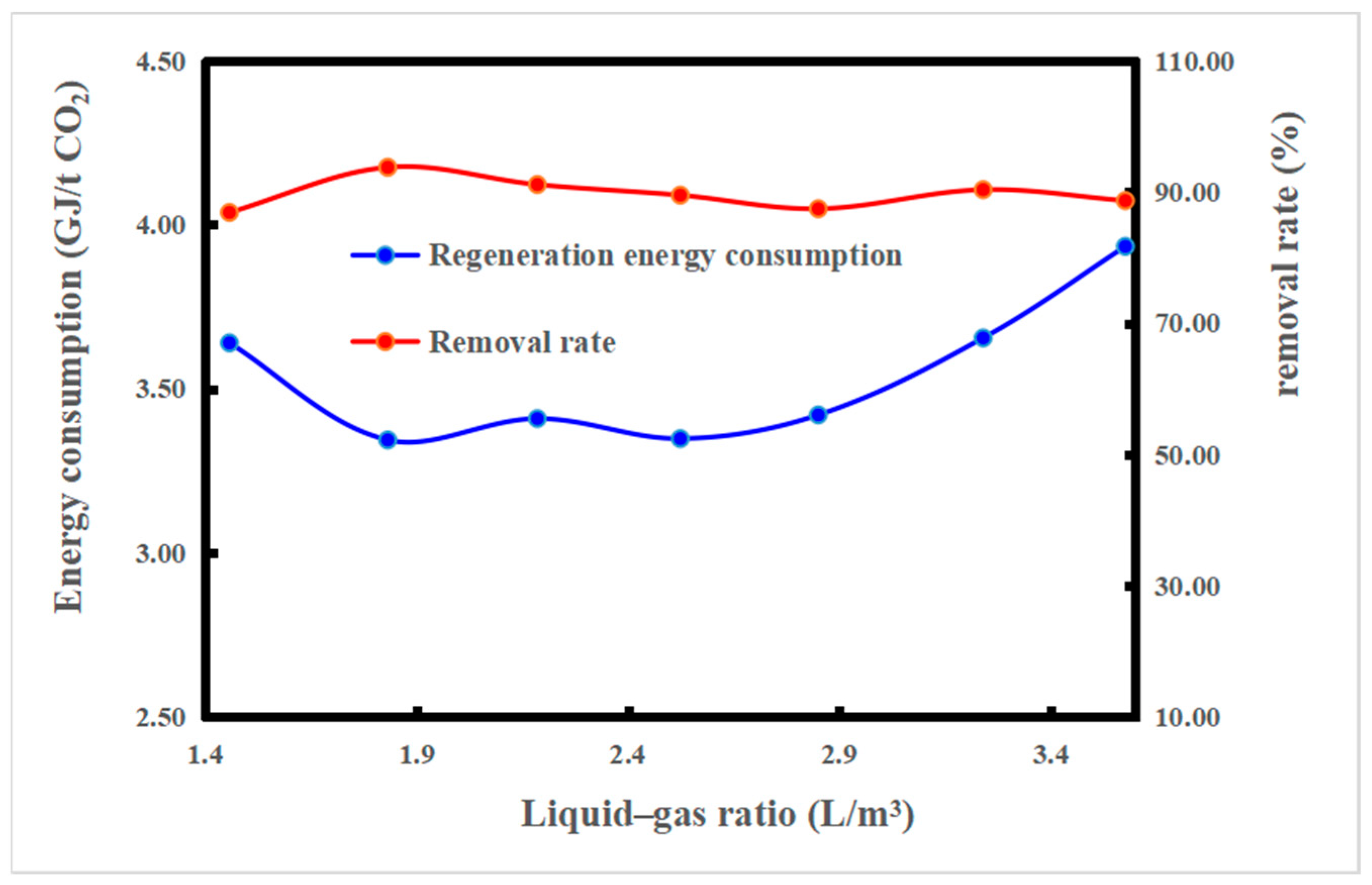
The regeneration energy consumption and CO2 removal rate of the NICE absorbent are shown in Figure 5. Since an increase in the liquid–gas ratio promotes the absorption process but reduces the desorption process efficiency, the energy consumption of regeneration presents a U-shaped trend with an increase in the liquid–gas ratio. Combined with the curve of the CO2 removal rate, which needed over 80% and had the lowest regeneration energy consumption, the optimal liquid–gas ratio was determined. In this section, the lowest regeneration energy consumption was 3.34 GJ/t CO2, the highest CO2 removal rate was 94%, and the optimal liquid–gas ratio was 1.82 L/m3. The optimal liquid–gas ratio was reduced by 50% compared with that (3.64 L/m3) obtained with the base absorbent (30% MEA) tested on the same platform.
3.2. The Effect of Regeneration Pressure
The regeneration pressure directly affects the CO2 concentration of the product gas and the temperature in the regeneration tower, which directly affect the regeneration energy consumption of the system. The product gas is composed of CO2 and saturated water vapor, and the amount of saturated water vapor is only related to the temperature in the product. In the process of optimizing the regeneration pressure, the steam consumption was maintained at 60 kg/h, the liquid–gas ratio was 1.82 L/m3, the regeneration pressure varied from 101 to 191 kPa, and other process conditions remained unchanged.
When the regeneration pressure increased, the internal temperature in the desorption tower increased, and the partial pressures of water vapor and CO2 in the top gas of the desorption tower simultaneously increased. When the pressure was lower than the critical value, the partial pressure of CO2 increased rapidly, leading to an increase in the proportion of CO2 in the top gas of the desorption tower. In this case, less water was carried by the CO2 recycled from the top of the tower, reducing the latent heat required for regeneration. When the pressure was higher than the critical value, the partial pressure increased rapidly, and thus, the proportion of CO2 in the top gas of the desorption tower decreased [31]. Evidently, the critical parameter is the optimal regenerative pressure. At a pressure of 191 kPa, the outlet temperature in the reboiler increased from 104 °C to 117 °C, and the temperature in the regeneration tower increased from 92 °C to 101 °C, as shown in Figure 6. The results show that increasing the regeneration pressure can effectively reduce the heat loss of the system and improve the heat utilization efficiency in the regeneration process. The increasing temperature in the regeneration tower benefits the preheating of the rich liquid in the desorption tower and the fast desorption process, and the increasing temperature in the outlet of the reboiler benefits the slow desorption process of the absorbent. The actual regeneration energy consumption was consistent with the prediction.
As shown in Figure 7, the regeneration energy consumption decreased with an increase in the regeneration pressure. Due to the limited design of the device, it can only be pressurized to 191 kPa, with a minimum renewable energy consumption of 2.91 GJ/t CO2 and energy savings of 12%. The minimum regenerative pressure for the energy consumption of the base solvent tested on the same platform was 181 kPa, and the regenerative energy consumption was reduced by approximately 5%. Therefore, the NICE absorbent has an outstanding high-pressure desorption potential and is suitable for high-pressure desorption processes, which help to reduce energy consumption during the subsequent compression process.
3.3. The Effect of the Rich Liquid Fractional Flow Ratio
In the traditional desorption process, the rich liquid enters the heat exchanger for heat exchange with the lean liquid. The rich liquid fractional flow process feeds a portion of the rich liquid directly into the regeneration tower and the other part into the heat exchanger. In this process, the waste heat of the regenerating gas was used to heat the cold rich liquid. At the same time, the flow rate of the rich liquid into the heat exchanger decreased, which resulted in an increase in the temperature in the rich liquid at the outlet and a consequent increase in the utilization rate of the waste heat in the regeneration tower.
The test regeneration pressure remained at 191 kPa, the rich liquid fractional flow ratio was 0–29%, and the other process conditions remained unchanged. Figure 8 shows the change in the outlet temperature in the heat exchanger and the temperature in the regeneration tower when the liquid to rich flow ratio is varied. The outlet temperature in the heat exchanger and the tower temperature show the same trend of increasing first and subsequently decreasing with an increase in the rich liquid diversion ratio. When the split ratio was lower than 0.18, the decrease in the rich liquid fractional flow ratio did not affect the efficiency of the heat exchanger and induced an increase in the outlet temperature. At this time, the heat exchange between the cooling rich liquid and the hot product gas in the regeneration tower was sufficient, causing an increase in the temperature in the tower kettle. When the split ratio was greater than 0.18, a very low flow rate was observed, which led to a decrease in the heat exchanger efficiency. Furthermore, a large amount of cooling-rich liquid entered the regeneration tower, resulting in insufficient residual heat and temperature drop. Figure 9 shows the regenerative energy consumption corresponding to the rich liquid fractional flow ratio; the optimal rich liquid fractional flow ratio was determined to be 0.18. At this time, the regeneration energy consumption was 2.85 GJ/t CO2, the energy consumption was reduced by 2%, and the removal rate was greater than 80%. The lowest regeneration energy point was also the highest temperature point, and the regeneration energy reduced with the increasing temperature. The cold fractional flow directly into the top of regeneration tower could recycle the heat of the product gas. As a result, rich liquid fractional flow is suited to the NICE absorbent, and needs to be added in future process design.
3.4. The Effect of the Interstage Cooling
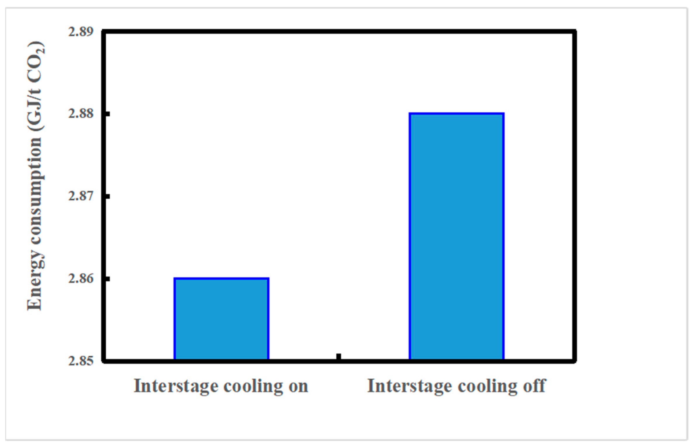
Interstage cooling can reduce the temperature in the absorption tower and strengthen the absorption process. The effect of interstage cooling can change depending on the column height at which it is applied [32]. However, the location of the inter-cooling was dictated by the layout of the pilot plant. The optimum location for inter-cooling was not determined. In this test, other process conditions were kept unchanged, and only the influence of interstage cooling on the regeneration energy consumption was investigated. Figure 10 shows the influence of interstage cooling on the energy consumption of the system. The energy consumption of open interstage cooling was 2.86 GJ/t CO2 and that of closed interstage cooling was 2.88 GJ/t CO2; the energy consumption increased by 0.7%. Interstage cooling had a small influence on the energy consumption of the base solution and could reduce the energy consumption by 5% in this pilot plant. This difference may be caused by two reasons. Firstly, the NICE absorbent, compared with the base solution, can still maintain a certain absorptive capacity at a high temperature, which is conducive for reducing the absorption–desorption temperature difference and offers a direction for further improvement in the process. Secondly, the location of the inter-cooling does not fit with the NICE absorbent, where the absorbent still has a high capture ability and does not need to be cold.
3.5. Comparison between the NICE Solvent and MEA
Compared with the base absorbent (30% MEA) tested on the same platform, the NICE absorbent showed a low regeneration energy consumption of 2.85 GJ/t CO2, where the optimal liquid–gas ratio was 1.82, as shown in Table 1. The circulation volume of the NICE absorbent was half that of the base absorbent, and the operating cost of the NICE sorbent could be reduced by approximately 50%. The energy consumption of the NICE absorbent was approximately 70% that of the base absorbent, which could also reduce the energy cost by 30%. Contrarily, a relatively low circulation volume of the absorbent implies that a relatively small facility can be utilized, and the equipment capital can be reduced by approximately 10–20%. Thus, this test exemplifies the excellent potential of the NICE absorbent for industrial applications.
4. Conclusions
The absorption performance of the NICE absorbent was studied in a pilot absorbent platform at the Zhejiang University, and the effects of the liquid–gas ratio, regeneration pressure, rich liquid fractional flow, and interstage cooling on energy consumption were investigated. By maintaining the maximum flue gas flow and a removal rate greater than 80%, the minimum regeneration energy consumption of 2.85 GJ/t CO2 was achieved, and the corresponding process parameters were as follows: the steam consumption was 60 kg/h, the lean liquid flow rate was 0.5 m3/h, the liquid–gas ratio was 1.82 L/m3, the regeneration pressure was 191 kPa, the interstage cooling temperature was 40 °C, and the rich liquid fractional flow ratio was 0.18. The test initially demonstrated the industrial feasibility and potential for capital and operating cost savings in the production of the NICE absorbent. This work has shown a good industrial application prospect of high-capacity absorbents, which also can reach a similar regeneration energy consumption in comparison to traditional low reaction heat absorbents. In this way, many simply structured amines can be used to reduce the cost of absorbents. Additionally, the current absorption equipment is not suitable for high-capacity and low liquid–gas ratio absorbents. The traditional capture system cannot reach full potential of high-capacity absorbents; although, increasing the flue gas flow can be a solution. A novel capture system that is suitable for the high-capacity absorbents must be designed in future works, which is the biggest challenge for the broad application of high-capacity absorbents.
5. Patents
Zhang Shizhe, Li, Zhao Xinglei, Method and system for capturing carbon dioxide and/or sulfur dioxide from gas stream. CN111185071A, 25 August 2011.
Author Contributions
Y.Y.: conceptualization, data curation, formal analysis, methodology, writing—original draft; X.Z.: supervision, writing—review; J.C.: supervision; M.F.: project administration, writing—review. All authors have read and agreed to the published version of the manuscript.
Funding
This research was funded by National Key R&D Program of China, grant number 2017YFB0603301; National Natural Science Foundation of China, grant number 21776005; China Energy Investment, grant number ST930021013.
Institutional Review Board Statement
Not applicable.
Informed Consent Statement
Not applicable.
Data Availability Statement
Not applicable.
Acknowledgments
This work was financially supported by the National Key R&D Program of China (2017YFB0603301), National Natural Science Foundation of China (21776005), and China Energy Investment (ST930021013). The authors also appreciate Ku Anthony at the NICE America Research Inc. for his assistance in editing the manuscript.
Conflicts of Interest
The authors declare no conflict of interest.
References
- IPCC. Climate Change 2014: Mitigation of Climate Change; Working Group III Contribution to the Fifth Assessment Report of the Intergovernmental Panel on Climate Change; Cambridge University Press: Cambridge, UK; New York, NY, USA, 2014. [Google Scholar]
- Bottoms, R.R. Organic bases for gas purification. Ind. Eng. Chem. 1931, 23, 501–504. [Google Scholar] [CrossRef]
- Campbell, M. Technology innovation & advancements for shell cansolv CO2 capture solvents. Energy Procedia 2014, 63, 801–807. [Google Scholar]
- Singh, A.; Stéphenne, K. Shell Cansolv CO2 capture technology: Achievement from first commercial plant. Energy Procedia 2014, 63, 1678–1685. [Google Scholar] [CrossRef]
- MIT. Petra Nova W.A. Parish Fact Sheet: Carbon Dioxide Capture and Storage Project, Carbon Capture and Sequestration Technologies Program at MIT. 2016. Available online: https://sequestration.mit.edu/tools/projects/wa_parish.html (accessed on 3 March 2022).
- Kwak, N.S.; Lee, J.H.; Lee, I.Y.; Jang, K.R.; Shim, J.-G. A study of the CO2 capture pilot plant by amine absorption. Energy 2012, 47, 41–46. [Google Scholar] [CrossRef]
- Zhang, X.; Zhang, X.; Liu, H.; Li, W.-S.; Xiao, M.; Gao, H.; Liang, Z. Reduction of energy requirement of CO2 desorption from a rich CO2-loaded MEA solution by using solid acid catalysts. Appl. Energy 2017, 202, 673–684. [Google Scholar] [CrossRef]
- Zhang, S.; Du, M.; Shao, P.; Wang, L.; Ye, J.; Chen, J.; Chen, J. Carbonic anhydrase enzyme-MOFs composite with a superior catalytic performance to promote CO2 absorption into tertiary amine solution. Environ. Sci. Technol 2018, 52, 12708–12716. [Google Scholar] [CrossRef]
- Hinai, A.A.; Zahra, M.A. Study of novel solvents and 2MAE blends for CO2 post-combustion capture. Energy Procedia 2017, 114, 686–692. [Google Scholar] [CrossRef]
- Nwaoha, C.; Tontiwachwuthikul, P. Carbon dioxide capture from pulp mill using 2-amino-2-methyl-1-propanol and monoethanolamine blend: Techno-economic assessment of advanced process configuration. Appl. Energy 2019, 250, 1202–1216. [Google Scholar] [CrossRef]
- Guo, H.; Li, C.; Shi, X.; Li, H.; Shen, S. Nonaqueous amine-based absorbents for energy efficient CO2 capture. Appl. Energy 2019, 239, 725–734. [Google Scholar] [CrossRef]
- Hwang, J.; Kim, J.; Lee, H.W.; Na, J.; Ahn, B.S.; Lee, S.D.; Kim, H.S.; Lee, H.; Lee, U. An experimental based optimization of a novel water lean amine solvent for post combustion CO2 capture process. Appl. Energy 2019, 248, 174–184. [Google Scholar] [CrossRef]
- Jing, G.; Qian, Y.; Zhou, X.; Lv, B.; Zhou, Z. Designing and screening of multi-amino-functionalized ionic liquid solution for CO2 capture by quantum chemical simulation. ACS Sustain. Chem. Eng. 2018, 6, 1182–1191. [Google Scholar] [CrossRef]
- Xiao, M.; Liu, H.; Gao, H.; Olson, W.; Liang, Z. CO2 capture with hybrid absorbents of low viscosity imidazolium-based ionic liquids and amine. Appl. Energy 2019, 235, 311–319. [Google Scholar] [CrossRef]
- Wang, X.; Akhmedov, N.G.; Hopkinson, D.; Hoffman, J.; Duan, Y.; Egbebi, A.; Resnik, K.; Li, B. Phase change amino acid salt separates into CO2-rich and CO2-lean phases upon interacting with CO2. Appl. Energy 2016, 161, 41–47. [Google Scholar] [CrossRef] [Green Version]
- Wang, R.; Yang, Y.; Wang, M.; Lin, J.-O.; Zhang, S.; An, S.; Wang, L. Energy efficient diethylenetriamine–1-propanol biphasic solvent for CO2 capture: Experimental and theoretical study. Appl. Energy 2021, 290, 116768. [Google Scholar] [CrossRef]
- Zhou, X.; Jing, G.; Lv, B.; Liu, F.; Zhou, Z. Low-viscosity and efficient regeneration of carbon dioxide capture using a biphasic solvent regulated by 2-amino-2-methyl-1-propano. Appl. Energy 2019, 235, 379–390. [Google Scholar] [CrossRef]
- Shen, Y.; Chen, H.; Wang, J.; Zhang, S.; Jiang, C.; Ye, J.; Wang, L.; Chen, J. Two-stage interaction performance of CO2 absorption into biphasic solvents: Mechanism analysis, quantum calculation and energy consumption. Appl. Energy 2020, 260, 114343. [Google Scholar] [CrossRef]
- Bihong, L.; Kexuan, Y.; Xiaobin, Z.; Zuoming, Z.; Guohua, J. 2-Amino-2-methyl-1-propanol based non-aqueous absorbent for energy-efficient and non-corrosive carbon dioxide capture. Appl. Energy 2020, 264, 114703. [Google Scholar] [CrossRef]
- Liu, F.; Fang, M.; Dong, W.; Wang, T.; Xia, Z.; Wang, Q.; Luo, Z. Carbon dioxide absorption in aqueous alkanolamine blends for biphasic solvents screening and evaluation. Appl. Energy 2019, 233, 468–477. [Google Scholar] [CrossRef]
- Wang, R.; Liu, S.; Wang, L.; Li, Q.; Zhang, S.; Chen, B.; Jiang, L.; Zhang, Y. Superior energy-saving splitter in monoethanolamine-based biphasic solvents for CO2 capture from coal-fired flue gas. Appl. Energy 2019, 242, 302–310. [Google Scholar] [CrossRef]
- Gao, W.; Liang, S.; Wang, R.; Jiang, Q.; Zhang, Y.; Zheng, Q.; Xie, B.; Toe, C.Y.; Zhu, X.; Wang, J.; et al. Industrial carbon dioxide capture and utilization: State of the art and future challenges. Chem. Soc. Rev. 2020, 49, 8584–8686. [Google Scholar] [CrossRef]
- Gao, T.; Selinger, J.L.; Rochelle, G.T. Demonstration of 99% CO2 removal from coal flue gas by amine scrubbing. Int. J. Greenh. Gas Control 2018, 83, 236–244. [Google Scholar] [CrossRef]
- Frimpong, R.A.; Nikolic, H.; Bahr, D.; Kiran, G.; Liu, K. Pilot scale testing of an advanced solvent in a 0.7 MWe post-combustion CO2 capture unit. Int. J. Greenh. Gas Control 2021, 106, 103290. [Google Scholar] [CrossRef]
- The Carbon Capture Demonstration Project of Guohua Jinjie Power Plant Was Successfully Electrified. Available online: http://www.ylrb.com/2021/0123/516209.shtml (accessed on 3 March 2022).
- Fagerlund, J.; Zevenhoven, R.; Thomassen, J.; Tednes, M.; Abdollahi, F.; Thomas, L.; Nielsen, C.J.; Mikoviny, T.; Wisthaler, A.; Zhu, L.; et al. Performance of an amine-based CO2 capture pilot plant at the Fortum Oslo Varme Waste to Energy plant in Oslo, Norway. Int. J. Greenh. Gas Control 2021, 106, 103242. [Google Scholar] [CrossRef]
- Ye, Y.; Zhang, H.; Wang, L.; Zhao, X. Development and pilot-scale study of NICE absorbent in CO2 capture process. Therm. Power Gener. 2022, in press. [Google Scholar] [CrossRef]
- Cannan, R.K.; Palmer, A.H.; Kibrick, A.C. The hydrogen ion dissociation curve of β-lactoglobulin. J. Biol. Chem. 1942, 2, 803–822. [Google Scholar] [CrossRef]
- Zhang, X.; Huang, Y.; Gao, H.; Luo, X.; Liang, Z. Zeolite catalyst-aided tri-solvent blend amine regeneration: An alternative pathway to reduce the energy consumption in amine-based CO2 capture process. Appl. Energy 2019, 240, 827–841. [Google Scholar] [CrossRef]
- Laugier, A.; Garai, J. Derivation of the ideal gas law. J. Chem. Educ. 2007, 11, 1832. [Google Scholar] [CrossRef]
- Van Straelen, J.; Geuzebroek, F. The thermodynamic minimum regeneration energy required for post-combustion CO2 capture. Energy Procedia 2011, 4, 1500–1507. [Google Scholar] [CrossRef] [Green Version]
- Li, K.; Cousins, A.; Yu, H.; Feron, P.; Tadé, M.; Luo, W.; Chen, J. Systematic study of aqueous monoethanolamine-based CO2 capture process: Model development and process improvement. Energy Sci. Eng. 2016, 4, 23–39. [Google Scholar] [CrossRef] [Green Version]
Figure 1.
Process flowchart of the test platform.

Figure 2.
Elevation layout of the test platform.

Figure 3.
Amine load titration system.

Figure 4.
Effect of the liquid–gas ratio on the CO2 loading capacity of lean and rich liquids.

Figure 5.
Effect of the liquid–gas ratio on the regeneration energy consumption and removal rate.

Figure 6.
Effect of the regeneration pressure on the temperature in the regeneration tower and the outlet of the reboiler. The steam consumption is 60 kg/h, liquid–gas ratio is 1.82 L/m3, interstage cooling temperature is 40 °C, and rich liquid fractional flow ratio is 0.
Figure 6.
Effect of the regeneration pressure on the temperature in the regeneration tower and the outlet of the reboiler. The steam consumption is 60 kg/h, liquid–gas ratio is 1.82 L/m3, interstage cooling temperature is 40 °C, and rich liquid fractional flow ratio is 0.

Figure 7.
Effect of the regeneration pressure on the regeneration energy consumption and removal rate.
Figure 7.
Effect of the regeneration pressure on the regeneration energy consumption and removal rate.

Figure 8.
Effect of the rich liquid fractional flow ratio on the temperature in the regeneration tower and the outlet of the heat exchanger. The steam consumption is 60 kg/h, liquid–gas ratio is 1.82 L/m3, regeneration pressure is 191 kPa, and interstage cooling temperature is 40 °C.
Figure 8.
Effect of the rich liquid fractional flow ratio on the temperature in the regeneration tower and the outlet of the heat exchanger. The steam consumption is 60 kg/h, liquid–gas ratio is 1.82 L/m3, regeneration pressure is 191 kPa, and interstage cooling temperature is 40 °C.

Figure 9.
Effect of the rich liquid fractional flow ratio on the regeneration energy consumption and removal rate.
Figure 9.
Effect of the rich liquid fractional flow ratio on the regeneration energy consumption and removal rate.

Figure 10.
Effect of interstage cooling on the regeneration energy consumption. The steam consumption is 60 kg/h, liquid–gas ratio is 1.82 L/m3, regeneration pressure is 191 kPa, and rich liquid fractional flow ratio is 29%.
Figure 10.
Effect of interstage cooling on the regeneration energy consumption. The steam consumption is 60 kg/h, liquid–gas ratio is 1.82 L/m3, regeneration pressure is 191 kPa, and rich liquid fractional flow ratio is 29%.


Table 1.
Comparing the regeneration energy consumptions and the optimal liquid–gas ratios of the NICE absorbent and 30%MEA.
Table 1.
Comparing the regeneration energy consumptions and the optimal liquid–gas ratios of the NICE absorbent and 30%MEA.
| Regeneration Energy Consumption (GJ/t CO2) | Optimal Liquid–Gas Ratio (L/m3) | |
|---|---|---|
| 30% MEA | 4.0 | 3.64 |
| NICE absorbent | 2.85 | 1.83 |
Publisher’s Note: MDPI stays neutral with regard to jurisdictional claims in published maps and institutional affiliations. |
© 2022 by the authors. Licensee MDPI, Basel, Switzerland. This article is an open access article distributed under the terms and conditions of the Creative Commons Attribution (CC BY) license (https://creativecommons.org/licenses/by/4.0/).
Share and Cite
MDPI and ACS Style
Ye, Y.; Zhao, X.; Chen, J.; Fang, M. Pilot-Scale Experimental Study of a New High-Loading Absorbent for Capturing CO2 from Flue Gas. Processes 2022, 10, 599. https://0-doi-org.brum.beds.ac.uk/10.3390/pr10030599
AMA Style
Ye Y, Zhao X, Chen J, Fang M. Pilot-Scale Experimental Study of a New High-Loading Absorbent for Capturing CO2 from Flue Gas. Processes. 2022; 10(3):599. https://0-doi-org.brum.beds.ac.uk/10.3390/pr10030599
Chicago/Turabian StyleYe, Yi, Xinglei Zhao, Jian Chen, and Mengxiang Fang. 2022. "Pilot-Scale Experimental Study of a New High-Loading Absorbent for Capturing CO2 from Flue Gas" Processes 10, no. 3: 599. https://0-doi-org.brum.beds.ac.uk/10.3390/pr10030599
Note that from the first issue of 2016, this journal uses article numbers instead of page numbers. See further details here.