
Effects of Outer Edge Bending on the Aerodynamic and Noise Characters of Axial Fan for Air Conditioners


1
School of Energy and Power Engineering, Huazhong University of Science and Technology, Luoyu Road No. 1037, Wuhan 430074, China
2
Chinese State Key Lab of Air-Conditioning Equipment and System Energy Conservation, Jinji Road No. 789, Zhuhai 519000, China
*
Authors to whom correspondence should be addressed.
Processes 2022, 10(4), 686; https://0-doi-org.brum.beds.ac.uk/10.3390/pr10040686
Submission received: 1 March 2022
/
Revised: 28 March 2022
/
Accepted: 29 March 2022
/
Published: 31 March 2022
(This article belongs to the Topic District Heating and Cooling Systems)
Abstract
:Outer edge bending is already used on the axial fan blades of air conditioners, reducing the leakage flow loss at the blade tip and suppressing the tip vortex development, thereby improving fan aerodynamic and acoustic performance. However, there are few studies on the multi-parameter design and optimization of this complicated structure, and most studies only focus on the overall sound pressure level rather than the sound quality when evaluating the fan noise. This study investigated the effects of outer edge bending structure on the aerodynamic performance and sound quality of air conditioners’ axial fans by experiments and numerical methods. Based on the orthogonal design method, the effects of three bending parameters, the circumferential starting angle, radial relative position, and the bending degree effects on the performance of the axial flow fan blade were analyzed, and the best efficiency scheme was selected. A comparative analysis of the preferred and the original bending schemes shows that the bending towards the blade suction surface successfully inhibits the development of tip leakage vortex at the blade tip, thereby achieving efficiency enhancement and noise reduction. The experimental results show that the preferred bending scheme with a 10° circumferential starting angle, 90% radial relative position, and 8% bending degree can effectively reduce the fan’s broadband noise within 200~1000 Hz by 0.54~2.68 dB (A) at different operating conditions. Additionally, the preferred bending blade with reasonably designed bending effectively reduced the loudness and roughness of the fan noise in the rated conditions, and the sound quality of the studied fan was correspondingly improved.
1. Introduction
The split-type air conditioners are widely used in residential and commercial applications to maintain air quality and the comfort of the indoor environment. However, air-conditioning equipment will inevitably produce aerodynamic sounds. These long-term, low-frequency, and annoying noises threaten the physical and mental health of those involved. Studies have shown that exposure to a noisy environment for a long time reduces people’s communication, cognition, and reasoning abilities [1], and their work efficiency is correspondingly reduced [2]. Air conditioners are mostly operated for long periods at night. Studies have shown that, if the noise in the bedroom exceeds 50 dB (A) at night, it may cause sleep disorders in certain groups of people [3], and long-term exposure to >50 dB (A) noise will potentially affect people’s endocrine and emotional well-being [4]. Therefore, high-level aerodynamic performance and low-level aeroacoustic noise are always expected for air conditioners.
Many studies on the aerodynamic noise of an air conditioner generally concluded that the noise of an outdoor unit mainly orients from its half-open axial fan [5]. The periodical interaction between the high-speed rotating blades and the stationary casing induces discrete rotating noise. In contrast, the vortex generated near the boundary layer and the blade tip produce broadband vortex noise. Jang et al. [6,7] studied the flow structure in a propeller fan by using laser Doppler velocimetry and large-eddy simulation. It was found that noise is oriented from three typical vortex structures: tip vortex, leading-edge separation vortex, and tip leakage vortex (TLV). Jiang et al. [8,9] also measured the flow patterns around the blades’ tip. The results illustrated that the tip vortex generated from the blade suction surface increases the turbulence intensity and dominates the fan flow noise of the outdoor unit. Zhu et al. [10] and Tian et al. [11] focused on the aerodynamic and aeroacoustic performance of outdoor unit fans with different grilles, showing that the vortex shedding from the blades and grille trailing edge contributed dominantly to the overall broadband noise level. Luo et al. [12] combined computational fluid dynamics (CFD) and computational aeroacoustics to study the effect of TLV on fan flow loss and aerodynamic noise. It is illustrated that the broadband noise in different frequency ranges is mainly related to the different vortex or turbulent flow between the fan blades.
Reasonable blade shape can reduce the blade tip vortex and the wake vortex shedding caused by flow separation to reduce the noise of such fan systems. The most striking features of this low-speed axial fan are its swept and skewed blade shape [13]. Previous studies have demonstrated that the forward-tilted blade reduces the total pressure loss near the rotor hub and expands the stable working range of the fan [14,15,16]. Meanwhile, sweeping the blades backward will increase the air velocity radial component, incrementing the downstream turbulence energy and fan noise [17,18]. Reasonable design of the leading [19] and trailing edge [20,21] can degrade the separation at the blade surfaces, weakening the trailing edge shedding vortex, and thereby reducing noise. Akkermans and Stürmer et al. [22,23] further proposed an active flow control technology, trailing edge blowing, to weaken the unsteady loading of the blade trailing edge, reduce the interaction between the rotor wake and the next stage, and achieve a significant noise reduction. In addition, as the vortex around the blade tips dominates the fan aerodynamic noise, specific flow control techniques are used to focus on controlling the leaking flow in the tip region. The blade design with a bending out-edge [5] or tip winglet [24,25] can reduce the pressure difference between the pressure surface and the suction surface, thereby reducing the flow loss in the tip clearance and reducing the pressure pulsation at the blade’s outer edge, and finally suppressing the tip vortex’s development. Meanwhile, a thickened blade tip [26] can improve the pressure distribution on the blade surface by using the local protrusion at the tip, improving both the fan aerodynamic and acoustic performances.
However, most of the above studies adopted Sound Pressure Level (SPL) when evaluating the noise level of an air-conditioner fan. It is gradually noticed that noise is a subjective feeling, and SPL is challenging to characterize the psychological experience toward the noise [27]. Hence, the Sound Quality Objective Evaluation (SQOE) index is usually introduced to evaluate noise thoroughly. Commonly used SQOE indicators mainly include loudness, roughness, clarity, continuity, pitch, and sharpness. Researchers select different indicators to evaluate the main characteristics of different sounds [28,29]. The nuisance represented by multi-parameter coupling is the evaluation parameter with high frequency [30]. Meanwhile, the autocorrelation function has been employed to objectively evaluate sound [31,32,33].
Previous studies demonstrated that a reasonably bent blade outer edge can improve the fan efficiency and sound. However, the investigations on the overall effects of bending position and bending degree were still insufficient. Moreover, the research on outer edge flanging is mainly concerned with SPL rather than sound quality. In comparison, most of the present works concerned with the sound quality are focus on the noise generated by the air-conditioning compressors rather than the fan. Therefore, it seems necessary and exciting to explore the effect of flanging blade out edge on the fan sound quality, which is one of the main topics of the present study.
In this study, critical geometric parameters, such as the radial, the circumferential position of the tip bend, and the degree of axial bending, were first extracted based on an axial impeller of a semi-open axial fan system for air conditioning. Then multiple sets of edge bending schemes with different combinations of sizes and positions were designed through the orthogonal test method, and their flow characteristics, the volumetric flow rate, and the efficiency were numerically compared. Finally, the preferred scenarios were selected, the bending effects on sound pressure and the quality of fan noises were experimentally analyzed. The relevant flanging parameters and the optimal parameters configuration in the present study reference technicians when designing a low-noise air-conditioner axial fan.
2. Model and Numerical Simulation
2.1. Geometric Model and Design of Bending Orthogonal Schemes
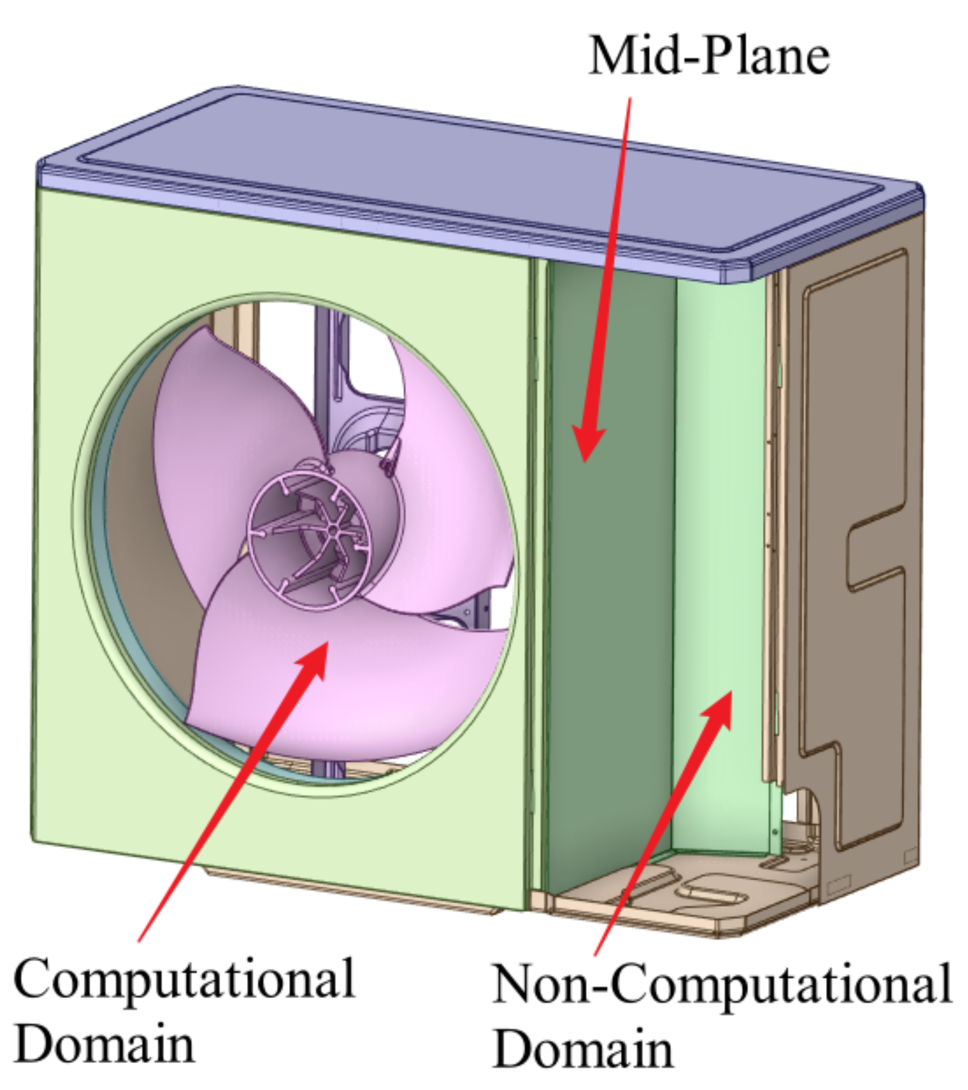
This study aimed to investigate the effects of tip bending parameters on the performance and aerodynamic noises of an air-conditioner fan. The outdoor unit of the air conditioner was employed as the subject. As shown in Figure 1, the outdoor unit consists of computational and non-computational domains (compressor domain) divided by a mid-plate. The computational domain is 800 mm × 450 mm × 650 mm. The air conditioner’s outdoor unit was equipped with the three-blade axial impeller, as shown in Figure 2. The impeller and its blade edge are free from further bending. The diameter and axial width of the impeller were 550 and 210 mm, respectively, and the hub diameter was 165 mm. The impeller was driven by a Direct Current (DC) motor fixed to the motor bracket, and the rotation speed (N) range and rated rotation speed of its blade were 600~920 and 840 rpm, respectively.
The circumferential starting angle, α; radial relative position, r/R; and degree of bending, ΔL/LH, reflected the bending geometric characteristics. Meanwhile, an orthogonal test was designed to study the optimal range of these parameters and the outer edge bending design. The bending features are illustrated in Figure 3. The circumferential starting angle of bending, α, is the angle between the bending starting position and the blade tip, where the bending extends from the starting position to the blade trailing edge (0°, 10°, 20°, and 0°).
The radial relative position is described by using the ratio r/R of the bending starting radius (r) to the impeller radius (R). For the current study, the r/R values were 0.8, 085, and 0.9. The bending degree is described by using the ratio ΔL/LH of the blade tip axial size change in the post-bending model relative to that of the fundamental impeller (ΔL) and the hub height (LH). The bending degrees, ΔL/LH, in this study were 2%, 4%, 6%, and 8%.
The orthogonal design of the outer edge bending parameters is presented in Table 1. The levels number of the circumferential starting angle (α), radial relative position (r/R), and degree of bending (ΔL/LH) are 4, 3, and 4, respectively. The Cartesian product of this combination had 48 combinations. Through orthogonal design, it is reduced to 16 parameter combination schemes.
2.2. Simulation Model and Numerical Methods
The simulation model is similar in structure to the experimental model. The inlet is equipped with a rectangular extended wind section as the outdoor unit of the air-conditioner section. A rectangular extended wind section completely covered the outlet. The inlet and outlet lengths are twice the diameter of the wind blade, and the calculation model is shown in Figure 4.
In this study, an ANSYS CFX solver was used to calculate the steady-state flow field, and the SST k-ω turbulence model [34] was used to model the RANS equation. The temperature was 273.15 K, the total pressure was 101.325 kPa, and the fluid was air at 20 °C. The relative static pressure was 0 Pa, and the walls were adiabatic and non-slip. The multi-reference frame (MRF) method [35] was used to simulate the flow of the rotation domain, and the data exchange between the rotation domain and the static domain was conducted by setting the interface. Although limitations and under-prediction were reported in simulating relevant features of the fan flow field when using the MRF mode [36], this method is still widely used in CFD calculations of rotational machines [37]. The finite volume method with mixed finite elements was used for the complete implicit solution, and the advection scheme and turbulence numerics are both high-resolution settings.
2.3. Independence of Grid and Verification of Simulation Result
The calculation model includes static domains (tube, inlet, and outlet domains) and rotation domains (impeller and envelope). Unstructured tetrahedral grids were used for calculations, and local densification on the leading and trailing edges of the blade and the sharply flowing areas was performed. At least ten prismatic boundary layers were set near the wall, and y+ < 5 of the first layer of grids near the border was ensured. The specific grid distribution shows in Figure 5.
The grid independence of flow field simulation was verified by using the rated conditions of the Case-Basic blade (rotation speed = 840 rpm, and relative static pressure = 0 Pa). Seven sets of volume grids with elements of were divided for calculation. The fan total pressure efficiency () of different grids was calculated to verify the independence of the grid. The fan total pressure efficiency ) was calculated by using the following equation:
where is the axial power and . Herein, N and M are the rotation speed and torque of impeller, respectively; is the fan full pressure, defined as the total pressure difference of the upstream reference plane, where Z = 300 mm section, and the rotation domain downstream reference plane, where Z = −200 mm section; is the volumetric flow rate monitored by the downstream reference plane, where Z = −200 mm. The parameters in the above formula are all in international standard units, and the total pressure efficiency calculated by different grids is shown in Figure 6a. The results show that the total pressure efficiency of the fan is unchanged with the increase in grid number when the number of grid cells is greater than . Finally, the grid number model was selected for subsequent simulation.
For the Case-Basic blade without bending, the simulation of multiple rotation speed conditions was performed. The rotation speed–volumetric flow rate curve for calculation and experiment is shown in Figure 6b. As observed, up to a 3.3% difference in volumetric flow rates was obtained by simulation and experiment under different rotation speeds. The calculation accuracy is high, and the existing grid division and settings meet the research requirements.
3. Simulation Results and Analysis
3.1. Effects of Bending Parameters on Fan Performance
A flow field simulation was performed on rated conditions (rotation speed 840 rpm, outlet relative static pressure 0 Pa) of 16 different bending blade schemes. After the flow field converges, the rotation domain upstream Z = 300 mm section and downstream Z = −200 mm section were selected for the statistical analysis of the total pressure efficiency (ηtf) and other parameters.
The orthogonal analysis method was used to analyze the effects of different factors on the aerodynamic performances of the fan by calculating the range value of each group of the orthogonal table. The range value and conversion of each level of each factor range value were calculated by using the total pressure efficiency under constant rotation speed (ηtf) as an indicator, as shown in Table 2. As observed, the influence of different factors on fan aerodynamic performances obtained by range value and conversion range value is that degree of bending (ΔL/LH) > circumferential starting position (α) > radial relative position (r/R). The preferred solution is ΔL/LH = 8%, r/R = 90%, and α = 10°, just coincident with Case-10. Through the influence of different factors and levels on the total pressure efficiency of the fan, the effect of the circumferential starting position on the total pressure efficiency is increased and then decreased. However, the impact of the relative radial position on the total pressure efficiency decreases and then increases. The influence of the bending degree on fan total pressure efficiency first increased and then decreased and further increased.
Under rated conditions, the aerodynamic performance of different outer edge bending schemes is shown in Figure 7. The range of the volumetric flow rate, Qv, is 5909–6026 m3/h, which exceeds the rated volumetric flow rate of the fan blade of 5800 m3/h. Case-5~Case-7 and Case-14~Case-16 reveal that bending the circular starting angle, α, has a negligible effect on the volumetric flow rate, Qv. There is a more significant volumetric flow rate (Qv) when r/R = 80%~85% and ΔL/LH = 4~6%, indicating that the smooth transition of outer edge bending in a larger radial range is beneficial to reduce the attenuation of volumetric flow rate, Qv, caused by outer edge bending.
On the premise that the volumetric flow rate meets the design requirements, the total pressure efficiency, ηtf, was mainly used to measure the fan’s aerodynamic performance [16,24]. As show in Figure 7, under the rated conditions, the total pressure efficiency (ηtf) of different outer edge bending schemes ranges from 61.25% to 63.36%. The total pressure efficiency (ηtf) of some schemes is higher or lower than that of the Case-Basic. This indicates that only a reasonable bending design can improve the total pressure efficiency.
Upon further analysis, among the 16 orthogonal schemes, we founds that Case-10’s total pressure efficiency (ηtf) is the highest, reaching 63.36%, and 0.86% higher than the Case-Basic. The total pressure efficiency (ηtf) of Case-10~Case-12 is improved relative to Case-Basic, indicating that achieving a greater degree of bending within the smaller curvature of the blade tip improves the fan’s total pressure efficiency. Jung et al. [16] applied winglets on the axial flow fan, and this increased the tip leakage flow rate by 66%; however, it increased the efficiency by 0.7%. This study agrees with his result. At the same time, the axial power, Ws, of Case-10 and Case-12 is also smaller than that of other schemes. Based on the performance of each scheme, these two schemes are preferred for further research.
3.2. Effects of Preferred Schemes on the Fan Performance
The orthogonal analysis of numerical simulations of preferred schemes Case-Basic, Case-10, and Case-12 under 0 Pa static pressure and different rotation speeds was conducted to clarify the effects of the blade’s outer edge bending on the fan system’s performance curve. Figure 8a,b shows the rotation speed–flow rate and rotation speed–efficiency curves of different schemes under different rotation speeds. For Case-10 and Case-12 models, the flow rate reduction relative to the basic configuration under different rotation speeds is less than 1%, demonstrating that outer edge bending has little effect on the fan system’s flow rate under different conditions. Meanwhile, compared to the original blade under all rotation speeds, Case-10 has the highest efficiency. Specifically, the efficiency is 0.86% higher than the basic configuration under 840 rpm. Case-12 is lower than the basic configuration when the rotation speed is less than 680 rpm. As the rotation speed increased, the efficiency improved slightly more than the basic configuration.
As shown in Figure 7 and Figure 8a, outer edge bending caused attenuation of the volumetric flow rate of the axial impeller, and the greater the degree of bending, the more attenuation of volumetric flow rate, while the overall change of the volumetric flow rate was within 1%. Figure 8b shows the efficiency curves under different rotation speeds. The highest point of blade efficiency is 840 rpm under 0 Pa static pressure before and after bending. In Case-12, the efficiency improvement under optimized conditions is not significant, and there is an efficiency reduction at low rotation speeds. In Case-10, the efficiency improvement of the blade under optimized working conditions is substantial. It indicates that the fan efficiency is negatively correlated with the bending of the circular relative position and positively correlated with the degree of bending and radial relative position.
Comparisons of the surface pressure distribution clouds of the basic configuration and the preferred scheme (Case-10 and Case-12) are shown in Figure 9 and Figure 10. The high-pressure area of the pressure surface area of the suction surface of each model concentrates on the blade edge near the trailing edge, where tip bending mainly affects the flow characteristics. The fluid velocity in this area is high, and it is affected by the comprehensive influence of the tip vortex, tip leakage vortex, and trailing edge separation vortex. The flow is complex and has an essential impact on the fan performance. Case-Basic has a large pressure gradient in the high-pressure region of the outer edge of the blade on the pressure surface (Figure 9a) and has a smaller area in the low-pressure region on the suction surface (Figure 10a). It indicates that the load distribution and the work area are relatively concentrated. For the preferred Case-10 and Case-12, the high-pressure area on the pressure surface is distributed evenly (Figure 9b,c), and the low-pressure area on the suction side is enlarged (Figure 10b,c); thus, the overall load distribution is more uniform.
3.3. Effects of Preferred Schemes on Aerodynamic Noises
The noise level of an axial fan can be partly evaluated by flow characteristics, such as the vortex core in the impeller region and the turbulent kinetic energy on the blade surface [38]. The flow characteristics of two preferred schemes (Case-10 and Case-12) and the basic schemes were compared on the rated conditions. The turbulence kinetic energy distribution on the surface of the blades is shown in Figure 11. The blade-surface turbulence kinetic energy characterizes the blade-surface speed pulsation. The larger the speed pulsation, the greater the pressure pulsation is and the more evident the aerodynamic noises are. The intensity and position of the noise source can be indirectly determined by the blade’s surface turbulence kinetic energy distribution. As shown in Figure 11, the turbulence kinetic energy amplitude for all blades is located in the outer edge area of the impeller with fast speed change and complicated flow. A properly designed out-edge bending scheme could effectively reduce the turbulence kinetic energy amplitude and area, as this is conducive to reducing noise.
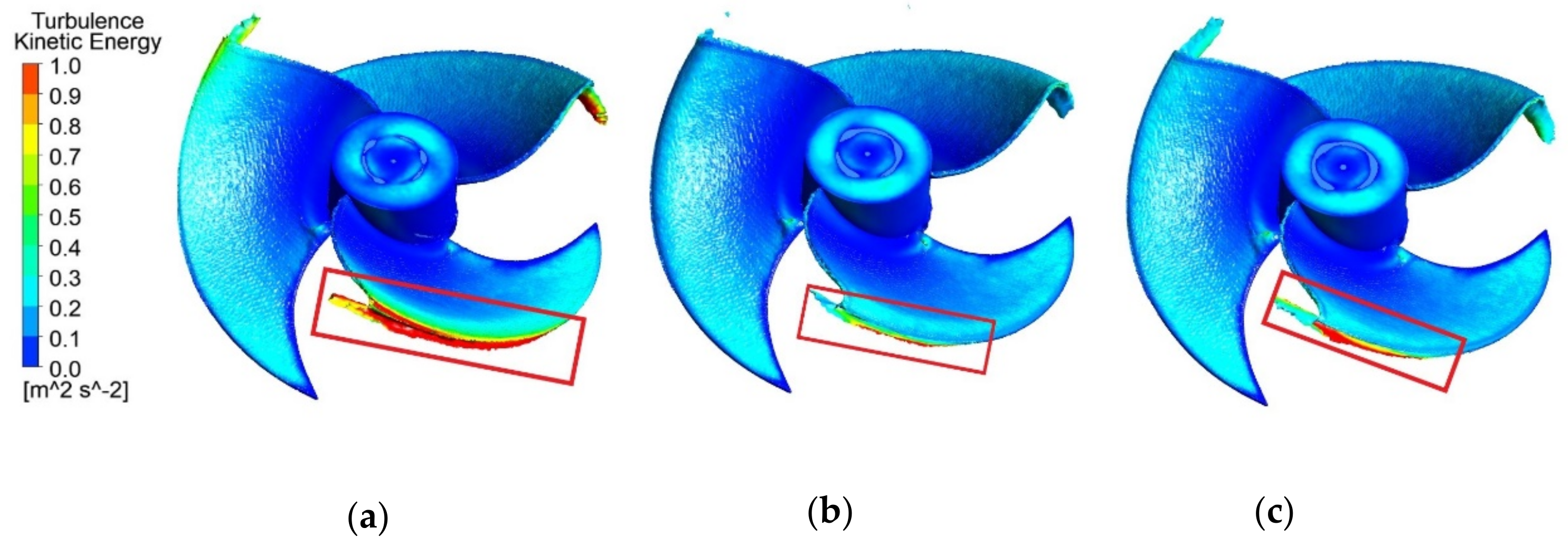
The aerodynamic noises of the axial impeller are closely related to the vortex structure near the blade tip [25,39]. The vortex core distribution in the impeller region allows for a better analysis of the bending effect on the vortex distribution and eddy energy at the blade tip. The 3D streamline diagram and turbulent kinetic energy distribution are used to analyze the flow characteristics of the tip vortex of the blade, and the results are shown in Figure 12 and Figure 13, respectively. As shown in Figure 12, a vortex structure is formed in the vicinity of the blade tip at the outer edge of the blade due to the leakage of the airflow. The leakage vortex structures of Case-10~Case-12 are shrunk relative to Case-Basic. The blade tip bending structure promotes the leakage of the outer edge of the blade to occur earlier, and the pressure transition from the pressure surface to the suction surface is smoother, thereby reducing the tip leakage vortex [25]. As shown in Figure 13, Case-Basic has a large amplitude of turbulent kinetic energy and occupies 1/2 of the outer edge of the blade. Compared with Case-Basic, Case-10 and Case-12 have significantly smaller turbulent kinetic energy amplitudes, and their area is reduced to 1/3 of the outer edge of the blade. This indicates that the bending structure makes the air flow smoothly on the pressure surface and the suction surface and weakens the reverse pressure gradient of the pressure surfaces and the suction surfaces [24]. The distribution of 3D streamlines and the turbulent kinetic energy at the outer edge of the blade indicate that the bending structure can dissipate the energy of the tip leakage vortex.
The fluid near the blade edge is turned and warped due to the pressure difference to form the tip vortex, creating a tip leakage vortex as the tip vortex develops and falls off. The formation and development of the vortex and the interaction with the blade make the blade tip area have greater speed and pressure pulsation, resulting in greater aerodynamic noises. The blade tip bending structure effectively reduces the strength and range of the blade tip vortex and the pressure and velocity pulsation on the outer edge of the blade tip. Meanwhile, reducing tip vortex and turbulence pulsation dissipation diminishes flow loss and flow channel blockage to a certain extent and improves impeller efficiency. Overall, the tip vortex of Case-10 has the smallest intensity and influencing zone and the most significant improvement in turbulence kinetic energy distribution, exhibiting better comprehensive performance.
4. Experimental Results
4.1. Experimental Results of Aerodynamic Performances
Three-dimensional printing models were performed on preferred schemes Case-10 (Figure 14) and Case-12. Volumetric flow rate–rotation speed curves and volumetric flow rate–noise curves of the schemes were obtained through experiments for performance comparison analysis. The experimental platform for measuring the rotation speed–volumetric flow rate curve was established according to ISO 5801:2007 Standards. The results were converted into a standard volumetric flow rate for comparison. Figure 15 illustrates the measured Qv of the selected schemes under different rotation speeds. Experimental results revealed that the Qv of Case-10 and Case-12 is lower than those of Case-Basic under all conditions. The Qv attenuation of different working conditions was quantitatively compared. The Qv attenuation of Case-10 blades is 0.76~2.45%, and the Qv attenuation of Case-12 is 2.96~4.31%. The measured Qv attenuation is higher than that obtained by simulation. The maximum error of Qv was less than 4% between the simulation and experiment results, and the trend was consistent. The simulation error of Case-10 and Case-12 is larger than that of Case-Basic. The main reason is that the impeller of Case-10 and Case-12 is a 3D print prototype, and their strength will be smaller than that of Case-Basic. During the test, the fan blades will be deformed, and this will cause the experiment Qv to be small.
4.2. Experimental Results of SPL and Sound Quality
According to Chinese standard GB/T 7725-2019, the three impellers (Case-10, Case-12, and Case-Basic) were tested and verified by noise measurement experiments to investigate the effects of tip bending on SPL. The measurement was performed in a semi-anechoic laboratory. We set three measurement points on the front and center lines of the air conditioner’s outdoor unit. The distance from the unit is 1 m, and the height is 1/2 of the unit height plus 1 m. The test result is the average sound pressure of 3 points. The test site and noise test results are shown in Figure 16.
Figure 16b showed the volumetric flow rate–noise curves under different rotation speeds and 0 Pa static pressure. Under a rated rotation speed (840 rpm), the average A-weight Sound Pressures Level (ASPL) of Case-Basic, Case-10, and Case-12 was 57.6, 56.2, and 56.1 dB (A), respectively. Under all conditions and constant volumetric flow rate, the ASPL in Case-10 and Case-12 was reduced by 0.54~2.68 and 0.47~1.83 dB (A), respectively, compared to Case-Basic. The measured noise data agree with the turbulence kinetic energy analysis result, suggesting that the ASPL noise-level evaluation method based on fan efficiency and turbulence kinetic energy obtained by RANS simulations has high accuracy.
A fast Fourier-transform (FFT) analysis was performed on the raw SPL data collected in the noise measurement experiments. Figure 17a shows the ASPL spectrum curve of the three blades under rated conditions. The bending characteristics mainly reduce the broadband noise within 400~1000 Hz, which has a limited impact on the discrete noise. Therefore, the bending features lessen the intensity and scale of the tip vortex, and this can effectively reduce the vortex noise.
The sound-quality objective evaluation indexes loudness, sharpness, and roughness were selected as the evaluation target parameters. Loudness represents people’s subjective feelings of sound size. Figure 17b is the loudness spectrum of the experimental blade, showing the loudness in each critical frequency band, according to ISO 532-1-2017. The 24 crucial bands (Bark) were proposed by Eberhard Zwicker for the resonance frequency points of the particular structure of the human ear [40]. In the low-frequency band (critical frequency band < 14 Bark), the loudness of Case-12 and Case-10 is smaller than Case-Basic. In the high-frequency band (critical frequency band > 14 Bark), the loudness of Case-10 is greater than Case-12 and Case-Basic, suggesting that its loudness is sensitive to bending position changes. Hence, adjusting the bending position improves the loudness of the sound. Additionally, the loudness in the low-frequency range is sensitive to changes in the degree of bending and can be controlled by adjusting the degree of bending.
The loudness curves of the three blades in the loudness spectrum were integrated from 0 to 24 Bark to obtain the total loudness of the blades under rated conditions. The total loudness of Case-Basic, Case-10, and Case-12 was 8.43, 8.28, and 7.83 sones, respectively. The ASPL and loudness evaluation show that the blade’s outer edge bending characteristics positively affect the blade noise improvement. The test results are in line with the trend of simulation results.
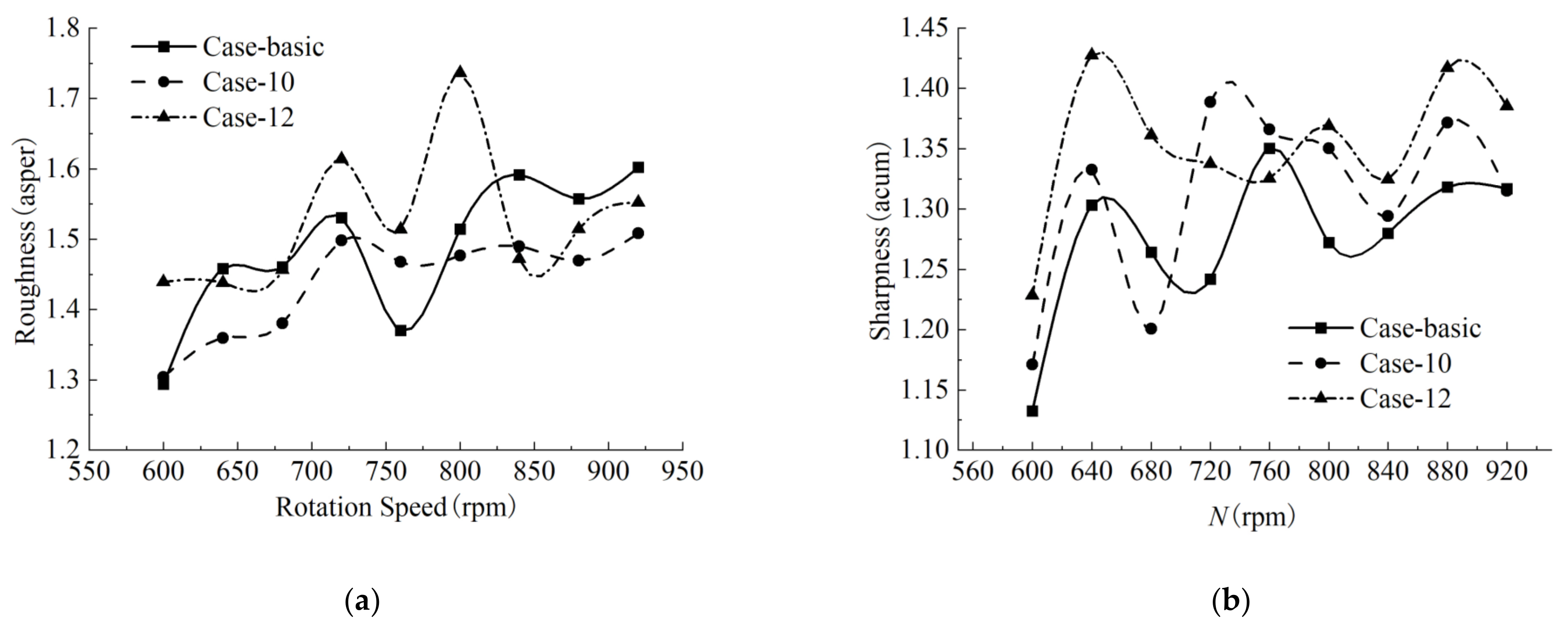
The roughness mainly reflects the amplitude modulation characteristics of sound, and the unit is asper. The sharpness measures the excessive high-frequency sound content, and the unit is acum. Figure 18 shows the roughness and sharpness of different blades under different rotation speeds. Figure 18a shows the roughness curves of the three blades under different rotation speeds. Case -10 roughness is lower than Case-12 and Case-Basic under most rotation speeds; and the change is stable and has an excellent overall performance. The roughness changes drastically, and its amplitude reflects the sound rougher; therefore, the bending characteristics will make the sound delicate and acceptable. The higher the sharpness, the higher the sound energy in the high-frequency range, harsher to hear. Figure 18b shows the sharpness curves of the three blades under different rotation speeds. The bending characteristics increase the sound sharpness to a certain extent. In summary, a reasonably designed blade outer edge bending can effectively reduce the noise loudness and roughness and improve the sound quality under a slight increase in sharpness.
5. Conclusions
In this study, numerical simulation combined with an aerodynamic experiment was used to study the outer edge bending of the impeller in an axial fan of an air conditioners’ outdoor unit. The influence of the bending characteristics on aerodynamic performances and noise characteristics of the fan were analyzed. The following conclusions were drawn:
- (1)
- After bending, the impellers’ volume flow rates were reduced to varying degrees, while their total pressure efficiency was slightly improved. However, the fan aerodynamic performance change affected by the outer edge bending is negligible. A well-designed impeller outer edge bend improves the load distribution on the blade surfaces, thereby increasing the total pressure efficiency of the impeller.
- (2)
- Simulation and experimental results showed that the smooth transition of the outer edge bending in a large radial range minimizes the volume flow rate attenuation caused by outer edge bending. The impeller’s total pressure efficiency was improved by a large degree of bending in a small radial range. The orthogonal parameter analysis showed that the bending degree affects fan efficiency more than the circumferential starting and radial relative positions.
- (3)
- Fan blade design with a significant degree of bending in a small radial range could effectively weaken the tip vortex strength, reduce the pressure pulsation on the blade tip, and reduce the SPL of the fan. For the Case-10 solution with the best noise-reduction effect, the noise of Case-Basic was reduced by 0.54~2.68 dB(A) under the same volumetric flow, and the total pressure efficiency of the rated working condition was increased by 0.68%.
- (4)
- The bending characteristics mainly reduced fans’ broadband noise among 200~1000 Hz, and the improvement of discrete noise was relatively limited. An analysis of the sound quality showed that the rationally designed outer edge bending scheme had lower loudness and roughness, which effectively improved the sound quality of fan noise.
Author Contributions
Conceptualization, B.L., J.W. and J.X.; methodology, B.L. and J.Y.; software, B.L., Q.L. and J.Y.; validation, J.Y., J.W. and J.X.; formal analysis, B.L.; investigation, B.L. and Q.L.; resources, B.L.; data curation, B.L. and Q.L.; writing—original draft preparation, B.L. and Q.L.; writing—review and editing, B.L., B.J., J.W. and J.X.; visualization, B.L.; supervision, J.W. and J.X.; project administration, B.L.; funding acquisition, J.W. All authors have read and agreed to the published version of the manuscript.
Funding
This research was supported by the Zhuhai Basic and Applied Basic Research Foundation. ZH22017003200007PWC.
Institutional Review Board Statement
Not applicable.
Informed Consent Statement
Not applicable.
Data Availability Statement
Not applicable.
Acknowledgments
The authors thank the SKL of Air-Conditioning Equipment and System Energy Conservation for providing computational and experimental resources. The authors also appreciate HUST for providing technical support.
Conflicts of Interest
The authors declare no conflict of interest.
References
- Kim, S.C.; Park, K.S.; Kim, K.W. The Study on Affecting Subject Accomplishment by Noise. J. Ergon. Soc. Korea 2010, 29, 121–128. [Google Scholar]
- Kim, K. Sources, Effects, and Control of Noise in Indoor/Outdoor Living Environments. J. Ergon. Soc. Korea 2015, 34, 265–278. [Google Scholar] [CrossRef] [Green Version]
- Stansfeld, S.A.; Matheson, M.P. Noise pollution: Non-auditory effects on health. Br. Med. Bull. 2003, 68, 243–257. [Google Scholar] [CrossRef]
- Ising, H.; Gunther, T. Interaction between noise-induced stress and magnesium losses: Relevance for long-term health effects. In Proceedings of the INTER-NOISE and NOISE-CON Congress and Conference Proceedings, Budapest, Hungary, 25 August 1997; pp. 1258–1263. [Google Scholar]
- Zhao, X.; Sun, J.; Zhang, Z. Prediction and measurement of axial flow fan aerodynamic and aeroacoustic performance in a split-type air-conditioner outdoor unit. Int. J. Refrig. 2013, 36, 1098–1108. [Google Scholar] [CrossRef]
- Jang, C.-M.; Furukawa, M.; Inoue, M. Analysis of Vortical Flow Field in a Propeller Fan by LDV Measurements and LES—Part II: Unsteady Nature of Vortical Flow Structures Due to Tip Vortex Breakdown. J. Fluids Eng. 2001, 123, 755–761. [Google Scholar] [CrossRef]
- Jang, C.-M.; Furukawa, M.; Inoue, M. Analysis of Vortical Flow Field in a Propeller Fan by LDV Measurements and LES—Part I: Three-Dimensional Vortical Flow Structures. J. Fluids Eng. 2001, 123, 748–754. [Google Scholar] [CrossRef]
- Jiang, C.L.; Tian, J.; Ouyang, H.; Chen, J.P.; Chen, Z.J. Investigation of air-flow fields and aeroacoustic noise in outdoor unit for split-type air conditioner. Noise Control. Eng. J. 2006, 54, 146–156. [Google Scholar] [CrossRef]
- Jiang, C.L.; Chen, J.P.; Chen, Z.J.; Tian, J.; Hua, O.Y.; Du, Z.H. Experimental and numerical study on aeroacoustic sound of axial flow fan in room air conditioner. Appl. Acoust. 2007, 68, 458–472. [Google Scholar] [CrossRef]
- Zhu, Y.J.; Ouyang, H.; Du, Z.H. Experimental and numerical investigation of noise generated by rotor blade passing an exhaust grille. Noise Control. Eng. J. 2008, 56, 225–234. [Google Scholar] [CrossRef]
- Jie, T.; Ouyang, H.; Wu, Y.D. Experimental and numerical study on aerodynamic noise of outdoor unit of room air conditioner with different grilles. Int. J. Refrig. 2009, 32, 1112–1122. [Google Scholar]
- Luo, B.; Chu, W.L.; Zhang, H.G. Tip leakage flow and aeroacoustics analysis of a low-speed axial fan. Aerosp. Sci. Technol. 2020, 98, 105700. [Google Scholar] [CrossRef]
- Vad, J. Aerodynamic effects of blade sweep and skew in low-speed axial flow rotors at the design flow rate: An overview. Proc. Inst. Mech. Eng. Part. A 2008, 222, 69–85. [Google Scholar] [CrossRef]
- Li, Y.; Liu, J.; Ouyang, H.; Du, Z.-H. Internal flow Mechanism and Experimental Research of low Pressure Axial fan with Forward-Skewed Blades. J. Hydrodyn. 2008, 20, 299–305. [Google Scholar] [CrossRef]
- Vad, J.; Kwedikha, A.R.A.; Horváth, C.; Balczó, M.; Lohász, M.M.; Régert, T. Aerodynamic effects of forward blade skew in axial flow rotors of controlled vortex design. Proc. Inst. Mech. Eng. Part. A 2007, 221, 1011–1023. [Google Scholar] [CrossRef]
- Ye, X.; Fan, F.; Zhang, R.; Li, C. Prediction of Performance of a Variable-Pitch Axial Fan with Forward-Skewed Blades. Energies 2019, 12, 2353. [Google Scholar] [CrossRef] [Green Version]
- Hurault, J.; Kouidri, S.; Bakir, F.; Rey, R. Experimental and numerical study of the sweep effect on three-dimensional flow downstream of axial flow fans. Flow Meas. Instrum. 2010, 21, 155–165. [Google Scholar] [CrossRef]
- Yang, B.; Gu, C.G. The Effects of Radially Distorted Incident Flow on Performance of Axial-Flow Fans with Forward-Skewed Blades. J. Turbomach. 2013, 135, 11039. [Google Scholar] [CrossRef]
- Zhou, S.; Li, H.; Wang, J.; Wang, X.; Ye, J. Investigation acoustic effect of the convexity-preserving axial flow fan based on Bezier function. Comput. Fluids. 2014, 102, 85–93. [Google Scholar] [CrossRef]
- Gulhane, N.; Patil, S.; Singh, K. Acoustic Analysis of Condenser Fan of Split Air Conditioner Using Numerical and Experimental Method. Int. J. Air Cond. Refrig. 2015, 23, 1550012. [Google Scholar] [CrossRef]
- Wang, M.; Liu, X. Numerical investigation of aerodynamic and acoustic characteristics of bionic airfoils inspired by bird wing. Proc. Inst. Mech. Eng. Part. G 2018, 233, 4004–4016. [Google Scholar] [CrossRef]
- Akkermans, R.; Stuermer, A.; Delfs, J.W. Active Flow Control for Interaction Noise Reduction of Contra-Rotating Open Rotors. AIAA J. 2016, 54, 1413–1423. [Google Scholar] [CrossRef]
- Stürmer, A.; Akkermans, R.A.D. Multidisciplinary analysis of CROR propulsion systems: DLR activities in the JTI SFWA project. CEAS Aeronaut. J. 2014, 5, 265–277. [Google Scholar] [CrossRef] [Green Version]
- Jung, J.H.; Joo, W.-G. Effect of tip clearance, winglets, and shroud height on the tip leakage in axial flow fans. Int. J. Refrig. 2018, 93, 195–204. [Google Scholar] [CrossRef]
- Lim, T.-G.; Jung, J.H.; Jeon, W.-H.; Joo, W.-G.; Minorikawa, G. Investigation study on the flow-induced noise by winglet and shroud shape of an axial flow fan at an outdoor unit of air conditioner. J. Mech. Sci. Technol. 2020, 34, 2845–2853. [Google Scholar] [CrossRef]
- Kim, Y.-I.; Lee, S.-Y.; Lee, K.-Y.; Yang, S.-H.; Choi, Y.-S. Numerical Investigation of Performance and Flow Characteristics of a Tunnel Ventilation Axial Fan with Thickness Profile Treatments of NACA Airfoil. Energies 2020, 13, 5831. [Google Scholar] [CrossRef]
- Blauert, J. Communication Acoustics. In Psycho-Acoustics and Sound Quality; Springer: Berlin, Heidelberg, 2005; pp. 139–162. [Google Scholar]
- Kuwano, S.; Namba, S.; Kurakata, K.; Kikuchi, Y. Evaluation of broad-band noise mixed with amplitude-modulated sounds. Acoust. Sci. Technol. 1994, 15, 131–142. [Google Scholar] [CrossRef] [Green Version]
- Park, S.G.; Park, J.T.; Seo, K.W.; Lee, G.B.J. Comparison of the Sound Quality Characteristics for the Outdoor Unit according to the Compressor Model. In Proceedings of the International Compressor Engineering Conference, Purdue University, West Lafayette, IN, USA, 16–19 July 2012. [Google Scholar]
- Feldmann, C.; Carolus, T.; Schneider, M. A Semantic Differential for Evaluating the Sound Quality of Fan Systems. In Proceedings of the Asme Turbo Expo Turbomachinery Technical Conference & Exposition, Charlotte, NC, USA, 26–30 June 2017. [Google Scholar]
- Soeta, Y.; Onogawa, E. Multidimensional Psychological Evaluation of Air Conditioner Sounds and Prediction via Correlation Parameters. Front. Built Environ. 2021, 7, 77. [Google Scholar] [CrossRef]
- Li, H.; Chen, K.; Wang, X.; Gao, Y.; Yu, W. A perceptual dissimilarities based nonlinear sound quality model for range hood noise. J. Acoust. Soc. Am. 2018, 144, 2300. [Google Scholar] [CrossRef]
- Soeta, Y.; Shimokura, R. Sound quality evaluation of air-conditioner noise based on factors of the autocorrelation function. Appl. Acoust. 2017, 124, 11–19. [Google Scholar] [CrossRef]
- Menter, F.R. Two-equation eddy-viscosity turbulence models for engineering applications. AIAA J. 1994, 32, 1598–1605. [Google Scholar] [CrossRef] [Green Version]
- ANSYS, Inc. ANSYS CFX Solver Theory Guide, Release 18, 2nd ed.; ANSYS, Inc.: Canonsburg, PA, USA, 2019. [Google Scholar]
- Franzke, R.; Sebben, S.; Bark, T.; Willeson, E.; Broniewicz, A. Evaluation of the Multiple Reference Frame Approach for the Modelling of an Axial Cooling Fan. Energies 2019, 12, 2934. [Google Scholar] [CrossRef] [Green Version]
- Liu, H.; Jiang, B.Y.; Wang, J.; Yang, X.P.; Xiao, Q.H. Numerical and experimental investigations on non-axisymmetric D-type inlet nozzle for a squirrel-cage fan. Eng. Appl. Comp. Fluid Mech. 2021, 15, 363–376. [Google Scholar] [CrossRef]
- Darvish, M.; Frank, S.; Paschereit, C.O. Numerical and Experimental Study on the Tonal Noise Generation of a Radial Fan. J. Turbomach. 2015, 137, 363–376. [Google Scholar] [CrossRef]
- Pogorelov, A.; Meinke, M.; Schröder, W. Effects of tip-gap width on the flow field in an axial fan. Int. J. Heat Fluid Flow. 2016, 61, 466–481. [Google Scholar] [CrossRef]
- Zwicker, E. Subdivision of the Audible Frequency Range into Critical Bands (Frequenzgruppen). J. Acoust. Soc. Am. 1961, 33, 248. [Google Scholar] [CrossRef]
Figure 1.
Outdoor unit of air conditioner.

Figure 2.
Original blade model.

Figure 3.
Blade-bending design parameters.

Figure 4.
Flow domains of the model.

Figure 5.
Schematic of grid distribution.

Figure 6.
Verification of grid independence and simulation result. (a) Verification of grid independence, (b) Verification of simulation result.
Figure 6.
Verification of grid independence and simulation result. (a) Verification of grid independence, (b) Verification of simulation result.

Figure 7.
Calculation results of different schemes.

Figure 8.
Fan characteristics curve: (a) N-QV curve and (b) N-ηtf curve.

Figure 9.
Pressure distribution on the pressure surface: (a) Case-Basic, (b) Case-10, and (c) Case-12.
Figure 9.
Pressure distribution on the pressure surface: (a) Case-Basic, (b) Case-10, and (c) Case-12.

Figure 10.
Pressure distribution on the suction surface: (a) Case-Basic, (b) Case-10, and (c) Case-12.
Figure 10.
Pressure distribution on the suction surface: (a) Case-Basic, (b) Case-10, and (c) Case-12.

Figure 11.
Distribution of turbulence kinetic energy on blades of different schemes: (a) Case-Basic, (b) Case-10, and (c) Case-12.
Figure 11.
Distribution of turbulence kinetic energy on blades of different schemes: (a) Case-Basic, (b) Case-10, and (c) Case-12.

Figure 12.
Three-dimensional flow line of tip leakage vortex: (a) Case-Basic, (b) Case-10, and (c) Case-12.
Figure 12.
Three-dimensional flow line of tip leakage vortex: (a) Case-Basic, (b) Case-10, and (c) Case-12.

Figure 13.
Vortex core distribution at the blade tip of different scheme: (a) Case-Basic, (b) Case-10, and (c) Case-12.
Figure 13.
Vortex core distribution at the blade tip of different scheme: (a) Case-Basic, (b) Case-10, and (c) Case-12.

Figure 14.
Three-dimensional print prototype of case-10.

Figure 15.
Volume flow rate in simulations: (a) Case-Basic, (b) Case-10, and (c) Case-12.

Figure 16.
Noise test site and test data: (a) noise test site and (b) volumetric flow rate–noise.

Figure 17.
ASPL spectrum and loudness spectrum: (a) FFT frequency spectrum and (b) loudness spectrum.
Figure 17.
ASPL spectrum and loudness spectrum: (a) FFT frequency spectrum and (b) loudness spectrum.

Figure 18.
Roughness and sharpness of different blades under different rotation speeds: (a) roughness curve and (b) sharpness curve.
Figure 18.
Roughness and sharpness of different blades under different rotation speeds: (a) roughness curve and (b) sharpness curve.


Table 1.
Orthogonal schemes.
| Schemes | α (°) | r/R (%) | ΔL/LH (%) |
|---|---|---|---|
| Case-1 | 0 | 80 | 2 |
| Case-2 | 10 | 85 | 2 |
| Case-3 | 20 | 90 | 2 |
| Case-4 | 30 | 90 | 4 |
| Case-5 | 30 | 85 | 6 |
| Case-6 | 20 | 80 | 6 |
| Case-7 | 10 | 80 | 4 |
| Case-8 | 0 | 90 | 6 |
| Case-9 | 0 | 85 | 4 |
| Case-10 | 10 | 90 | 8 |
| Case-11 | 20 | 85 | 8 |
| Case-12 | 30 | 80 | 8 |
| Case-13 | 30 | 80 | 2 |
| Case-14 | 20 | 80 | 4 |
| Case-15 | 10 | 80 | 6 |
| Case-16 | 0 | 80 | 8 |
Table 2.
Orthogonal analysis.
| Case | A (α%) | B (r/R %) | C (ΔL/LH %) | |
|---|---|---|---|---|
| Case-1 | A1(0) | B1(80) | C1(2) | 61.84 |
| Case-2 | A2(10) | B2(85) | C1(2) | 61.58 |
| Case-3 | A3(20) | B3(90) | C1(2) | 61.71 |
| Case-4 | A4(30) | B3(90) | C2(4) | 61.28 |
| Case-5 | A4(30) | B2(85) | C3(6) | 61.25 |
| Case-6 | A3(20) | B1(80) | C3(6) | 61.61 |
| Case-7 | A2(10) | B1(80) | C2(4) | 61.99 |
| Case-8 | A1(0) | B3(90) | C3(6) | 62.46 |
| Case-9 | A1(0) | B2(85) | C2(4) | 62.13 |
| Case-10 | A2(10) | B3(90) | C4(8) | 63.36 |
| Case-11 | A3(20) | B2(85) | C4(8) | 62.47 |
| Case-12 | A4(30) | B1(80) | C4(8) | 62.55 |
| Case-13 | A4(30) | B1(80) | C1(2) | 61.71 |
| Case-14 | A3(20) | B1(80) | C2(4) | 62.35 |
| Case-15 | A2(10) | B1(80) | C3(6) | 62.14 |
| Case-16 | A1(0) | B1(80) | C4(8) | 62.12 |
| K1 | 62.14 | 62.04 | 61.71 | |
| K2 | 62.27 | 61.86 | 61.94 | |
| K3 | 62.04 | 62.20 | 61.87 | |
| K4 | 61.70 | / | 62.63 | |
| R | 0.57 | 0.34 | 0.91 | |
| R’ | 0.513 | 0.507 | 0.824 | |
| Optimal level | A2 > A1 > A3 > A4 | B3 > B1 > B2 | C4 > C2 > C3 > C1 | |
| Primary and secondary factors | C > A > B | |||
| Best match | C4A2B3 | |||
Note: R is the range value, R’ is the converted range value, and Ki (i = 1, 2, 3, 4) is the K value used to calculate the range and the converted range values.
Publisher’s Note: MDPI stays neutral with regard to jurisdictional claims in published maps and institutional affiliations. |
© 2022 by the authors. Licensee MDPI, Basel, Switzerland. This article is an open access article distributed under the terms and conditions of the Creative Commons Attribution (CC BY) license (https://creativecommons.org/licenses/by/4.0/).
Share and Cite
MDPI and ACS Style
Li, B.; Lu, Q.; Jiang, B.; Yang, J.; Wang, J.; Xie, J. Effects of Outer Edge Bending on the Aerodynamic and Noise Characters of Axial Fan for Air Conditioners. Processes 2022, 10, 686. https://0-doi-org.brum.beds.ac.uk/10.3390/pr10040686
AMA Style
Li B, Lu Q, Jiang B, Yang J, Wang J, Xie J. Effects of Outer Edge Bending on the Aerodynamic and Noise Characters of Axial Fan for Air Conditioners. Processes. 2022; 10(4):686. https://0-doi-org.brum.beds.ac.uk/10.3390/pr10040686
Chicago/Turabian StyleLi, Bin, Qi Lu, Boyan Jiang, Jinwen Yang, Jun Wang, and Junlong Xie. 2022. "Effects of Outer Edge Bending on the Aerodynamic and Noise Characters of Axial Fan for Air Conditioners" Processes 10, no. 4: 686. https://0-doi-org.brum.beds.ac.uk/10.3390/pr10040686
Note that from the first issue of 2016, this journal uses article numbers instead of page numbers. See further details here.