
Analysis of the Formation Mechanism of Surface Cracks of Continuous Casting Slabs Caused by Mold Wear


1
College of Metallurgy and Energy, North China University of Science and Technology, Tangshan 063210, China
2
Hebei Engineering Research Center of High Quality Steel Continuous Casting, Tangshan 063000, China
3
School of Materials Science and Engineering, Hebei University of Science and Technology, Shijiazhuang 050018, China
*
Author to whom correspondence should be addressed.
Processes 2022, 10(4), 797; https://0-doi-org.brum.beds.ac.uk/10.3390/pr10040797
Submission received: 8 March 2022
/
Revised: 12 April 2022
/
Accepted: 15 April 2022
/
Published: 18 April 2022
(This article belongs to the Special Issue High-Efficiency and High-Quality Continuous Casting Processes)
Abstract
:Surface cracks are easily produced after friction between continuous casting billets and copper layers in mold cavity, but the formation mechanism is not clear. Based on a steel-based hot-dip copper plating experiment, this study simulated the action behavior of copper adhering to the surface of a continuous casting billet after mold wear and systematically analyzed the formation mechanism of cracks caused by copper infiltration on the surface of the continuous casting billet. It is shown that when the copper liquid adheres to the surface of the slab, in addition to the diffusion of Cu in the steel, Fe is also dissolved in the copper liquid, accelerating the solidification of the copper liquid on the surface of the slab and forming a stable fusion combination between copper and steel. At the same time, due to the enrichment of the Fe-C phase and a large number of vacancies at the grain boundary, the grain boundary becomes the dominant area of copper–steel fusion bonding. For a continuous casting process in which the temperature is kept higher than 900 ℃, Cu’s solubility is high and the diffusion coefficient is very low in Fe, which makes it very difficult for Cu accumulated in the grain boundary to diffuse into the steel matrix during the continuous casting process, resulting in a grain boundary with a greatly weakened strength becoming the origin of cracks in the bending and straightening deformation of the billet.
1. Introduction
The enrichment of copper in the grain boundary region can easily lead to the generation of surface cracks in continuous casting billets [1]. Under general conditions, copper-induced surface cracks can be divided into two categories. In one, the steel itself contains copper, and the segregation of copper at high temperatures causes cracks, such as weather-resistant steel and acid-resistant steel [2,3]. In the other, the steel itself does not contain copper, but the friction between the primary shell and the copper mold under the action of static pressure from the molten steel leads to copper infiltration on the surface of the billet and causes surface cracks in the billet [4].
For copper-containing steel, Cu-Fe is extremely difficult to dissolve at room temperature, and some scholars classify it as a binary immiscible system [5,6], which indicates that even if there is only a small amount of copper in the steel, the trend of local enrichment can emerge. In particular, the high-temperature environment in the continuous casting process will accelerate the diffusion of copper and segregation in the grain boundary area, resulting in the grain boundary weakening, and then tearing in the subsequent deformation process.
Li et al. [7] found that high superheat casting and uneven cooling of continuous casting billets would lead to an abnormal coarse austenite grain and increase the enrichment of copper by studding the surface cracks of EAF steel billets. Imai N et al. [8] believed that the oxidation of steel surfaces would also aggravate the diffusion and enrichment of copper in the steel matrix to the surface. At the same time, they also found that during the diffusion process of copper, along with the deposition of nitrides and sulfides in the grain boundary, the grain boundary brittleness was improved, and the crack sensitivity was enhanced, so the deformation of copper-bearing steel in the third brittle zone should be avoided. There is still some controversy about the segregation behavior of copper at grain boundaries. Most scholars believe that the segregation of copper increases with time [9,10]. However, through experimental analysis and theoretical calculation, Xu [11] found that there was a limit value for the segregation behavior of copper, that is, when the copper segregation reached the limit, it would reversely diffuse into the crystal under the action of the concentration gradient. Xu Ting Dong defined the time corresponding to this limit value as the critical time, and with the increase in temperature, the critical time would be greatly shortened. Although there is no definite conclusion about the segregation behavior of copper in steel, it can be seen that for the continuous casting of copper-bearing steel, the strength of the secondary cooling water distribution should be appropriately reduced, and the uniform spray cooling should be ensured, which is beneficial to the control of copper-induced cracks.
For steel without copper, when the local surface of the slab rubs with the copper layer in the mold cavity, the probability of copper-induced cracks on the surface of the slab will increase significantly, especially the large section billets such as the slab and bloom. There is a general consensus that when a shell with a certain strength makes contact with the lower part of the mold, if the slag layer on the shell surface ruptures, and the exposed area of the billet makes contact with the copper layer of the mold and produces strong friction, the surface of the billet will be covered with a layer of copper. Under high temperatures, the copper will diffuse into the steel matrix along the grain boundary, thereby reducing the strength of the grain boundary, and then cracks are generated in the subsequent deformation process. This consensus is based on the discovery of enriched copper at the root of slab cracks, i.e., since the steel itself does not contain copper, the enriched copper may only come from the wear of the mold [1,4]. However, the consensus above does not reveal the nature of cracks on the surface of continuous casting billets due to copper infiltration in the mold, and its formation mechanism remains to be further studied.
The temperature of the primary shell at the outlet of the mold is usually above 1100 °C, which exceeds the melting point of copper. When the protective slag layer on the slab surface is partially damaged or discontinuous, the slab will have excessive friction with the mold, resulting in the stripping of the mold copper layer. The exfoliated copper adheres to the shell surface, which will melt into liquid under the action of high temperatures and keep adhering to the surface of the steel substrate. After being out of the mold, the exfoliated copper will repeatedly rise and cool under the action of secondary cooling water and will always be in the process of the repeated phase transformation of melting, solidification, re-melting and re-solidifying. Therefore, it is not difficult to see that in the continuous casting process, the adhesion of copper on the surface of the steel substrate is the root and key to the generation of copper-induced cracks, and the core is the interaction between the liquid copper and the high-temperature steel substrate. In order to clarify this problem, a hot-dip copper plating test of steel under continuous casting conditions was designed in this study to analyze the behavior of the stripped copper layer of the mold attached to the surface of the slab after remelting at high temperatures, so as to determine the formation mechanism of the cracks caused by copper infiltration on the surface of the slab.
2. Materials and Methods
Based on the temperature range of the outer surface of the continuous casting billet at the lower part of the mold and the foot roll area, hot-dipping experiments of a copper solution at 1100 °C, 1125 °C, 1150 °C, 1175 °C and 1200 °C were designed in this study, and the dipping time was 60 s. At the same time, in order to simulate the effect of casting speed to a certain extent, hot-dip plating experiments were designed at 1125 °C for 30 s, 45 s, 60 s and 180 s, respectively.
The experimental device was a high-temperature tube furnace. Ar gas was used to protect the furnace body during the heating and experiment. The specific experimental device is shown in Figure 1.
The raw material copper used in the hot-dip plating experiment was T2 industrial copper, the steel substrate was Q195 plain carbon steel, and the steel substrate size was 20 mm × 4 mm × 45 mm. The preheating temperature of the hot-dip plating was 600 °C, and the preheating time was 60 s. In order to prevent the oxidation of the steel surface during the preheating process, it was necessary to carry out alkali washing, acid washing and plating aid coating on the steel substrate surface before preheating. The specific components of the water solutions were:
Alkali washing solution: sodium hydroxide 50 g/L, sodium phosphate 30 g/L, sodium carbonate 20 g/L, sodium metasilicate 7 g/L, OP emulsifier 3 g/L, temperature 70 °C;
Acid washing solution: 10% dilute hydrochloric acid, room temperature;
Coating aid: potassium fluoride, 30g/L, room temperature.
Graphite flakes were added on the surface of the copper liquid after melting to prevent oxidation of the copper liquid. The cooling method of the hot-dip plating sample was water cooling.
3. Results
The potassium fluoride plating aid might form a dense protective film on the surface of the steel substrate, but its stabilizing temperature was within 700 ℃. Therefore, the steel substrate had to be kept in the 600 °C range, calibrated by the high-temperature furnace. After holding for 60 s, the steel substrate was quickly immersed in the copper solution for the hot-dip plating experiment.
When the copper liquid contacted the steel substrate far below its own temperature, it rapidly solidified on its surface and instantaneously formed a certain thickness of copper shell. Subsequently, the copper shell began to remelt rapidly under the convective heat transfer of the surrounding constant-temperature copper liquid. With the low temperature of steel substrate, when the temperature of plating aid was higher than 700 °C, it began to separate from the steel substrate. When the plating aid was completely stripped, the copper liquid could make full contact with the steel substrate. According to the mathematical model of the heat transfer of the hot-dip plating and the stability test results of the plating aid, it was estimated that the total time required from the beginning of the hot-dip plating to the copper liquid reaching the predetermined temperature and making full contact with the steel substrate would be about 10 s, so the designed experimental time met the necessity of making full contact between the copper and steel.
The solid-line temperature of the Q195 steel was above 1500 °C, which was much higher than the experimental temperature of the hot-dip plating. After the immersion plating was completed, the copper liquid attached to the surface of the steel substrate first cooled down and solidified and shrunk. Since the solidification shrinkage of the copper liquid at room temperature is much larger than that of steel [12], the formation of a stable bonding between copper and steel was the cause of the copper-induced cracks on the steel surface. Therefore, this study first analyzed and compared the cross-sectional microstructure of hot-dip coating samples to determine the bonding between copper and steel.
3.1. Microstructure Analysis
Figure 2 shows the cross-sections of the copper–steel bonding area during hot-dip plating for 60 s at different experimental temperatures. It can be seen from Figure 2 that although the thickness of the copper layer on the surface of the corresponding sample at different hot-dip temperatures is different, there is no obvious crack on the copper–steel interface. There is no obvious rule to follow for the thickness of the hot-dip copper coating at different temperatures. This is mainly because the thickness of the copper coating is affected by the pulling speed of the hot-dip plating sample. In the pulling process, the copper liquid will move downward due to inertia, resulting in the thickness of the copper layer on the upper part of the dip-plated sample being significantly smaller than that on the lower part of the sample [13]. Since the lifting speed was not fixed in this experiment, the irregular thickness of the hot-dip coating under different temperature conditions was formed. However, it can be seen from Figure 2 that the coating thickness has no effect on the bonding between copper and steel, indicating that the hot-dip temperature has little effect on the bonding between copper and steel.
For continuous casting, because the heat transfer in the corner of the billet belongs to two-dimensional heat transfer, and the heat transfer in the middle area belongs to one-dimensional heat transfer, there were some differences in the outer surface temperature of the whole cross-section of the billet. However, according to the experimental results of the hot-dip plating at different temperatures, the area of the copper-induced cracks on the surface of the billet had little relationship with the corresponding temperature, mainly depending on the contact state between the billet and the mold cavity. Local hot spots increased the friction between the mold and the shell at the corresponding position, increasing the risk of copper-induced cracks.
Figure 3 shows the cross-section of a copper–steel bonding zone at 1125 °C for different hot-dip plating times. It can be seen from Figure 3 that stable bonding can be formed between copper and steel under different hot-dipping times, which also means that the copper-induced crack on the slab surface had little relationship with the casting speed. However, it should be noted that with the increase in casting speed, the shell became thinner, and the friction between the slab surface and the mold wall increased, which leads to an increase in mold wear and further aggravates the generation of cracks.
3.2. Analysis on Combination of Copper and Steel
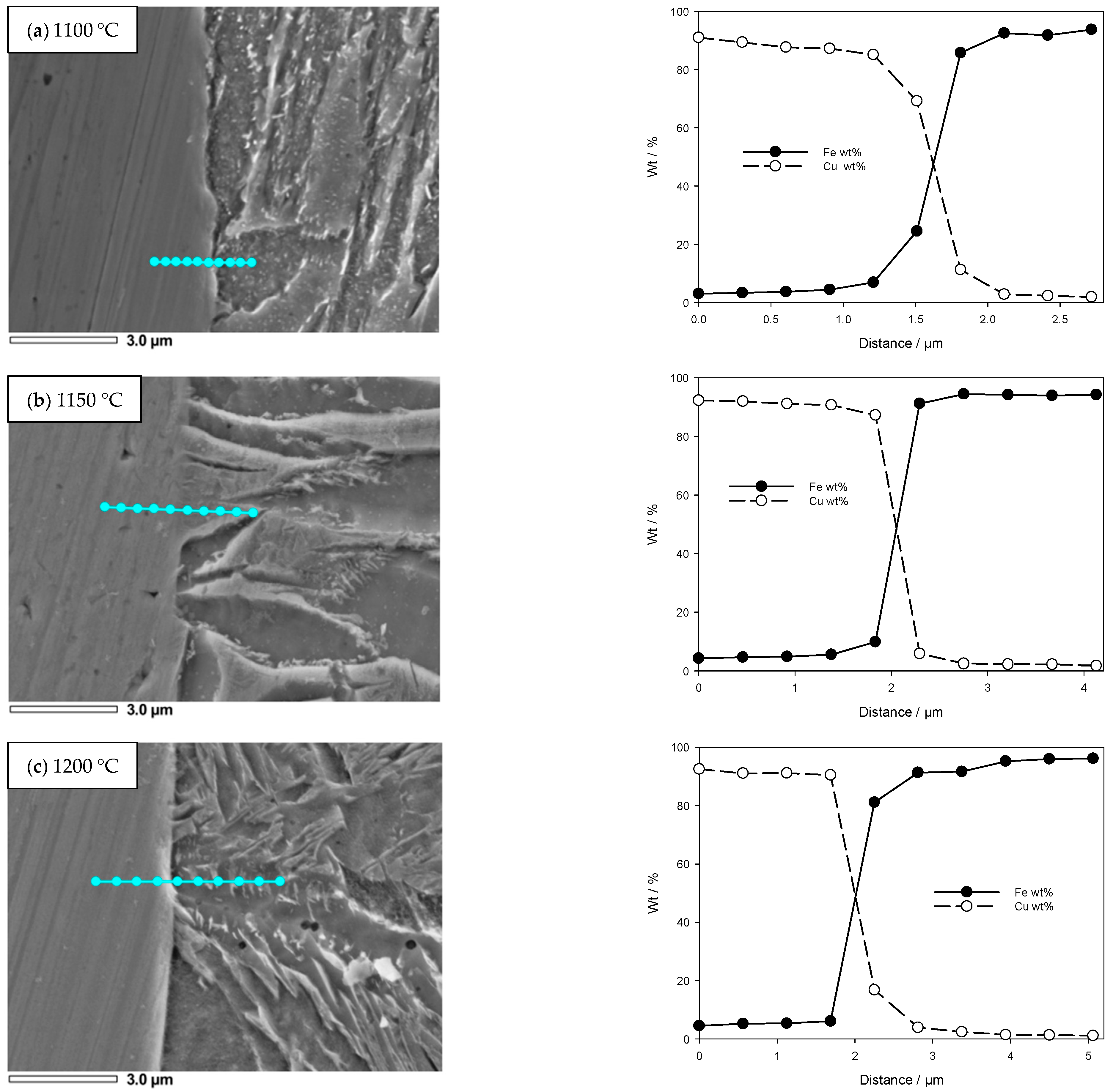
The metallographic structure analysis under a light microscope can only determine whether there is a defect in the bonding between the copper and steel under different process conditions, and cannot reflect the specific combination. Therefore, in this study, the copper–steel transition layers of three typical samples at 1100 °C, 1150 °C and 1175 °C were selected for electron probe line scanning analysis, and the results are shown in Figure 4a–c, respectively.
It can be seen from Figure 4 that a stable copper–steel transition layer formed at 1100 °C, 1150 °C and 1200 °C, but the thickness of the transition layer was thin. The thickness of the copper–steel transition layer under different hot-dip temperatures was extracted from the scanning results of the electron probe wire, and the results are shown in Figure 5. It can be seen from Figure 5 that although the thickness of copper–steel transition layer corresponding to 1150 °C was relatively large, the thickness of the transition layer corresponding to three hot–dip plating temperatures was not more than 1.5 μm, and the difference was not large.
Due to the severe impact of cooling water and the extrusion deformation of the fan section roller in the secondary cooling zone, if the bonding strength of the ultra-thin copper/steel transition layer is not high, the two will be stripped under the action of water scouring and mechanical extrusion in the secondary cooling zone. If the copper and steel are separated, copper-induced cracks will not occur due to mold friction. Therefore, the bonding strength of the copper–steel transition layer of the hot-dip coating sample was tested in this study. In the strength test experiment, the electronic tensile testing machine was used to bond the polished copper layer and the steel matrix layer on the steel bar of the tensile sample with strong adhesive. In this study, the samples with the thinnest transition layer after hot dipping at 1100 °C for 60 s were selected for detection, and the specific results are shown in Figure 6.
It can be seen from Figure 6 that the fracture of the sample occurred on the interface between the copper layer and the strong adhesive, and the load before the fracture was once more than 700 N, indicating that the bonding strength of the copper–steel transition layer was great. This shows that in the continuous casting process, the copper that has been attached to the surface of the steel substrate will not be peeled off due to the mechanical extrusion of the secondary cold roll and the erosion of the secondary cold water, and the extrusion of the secondary cold roll will also aggravate the expansion of copper on the surface of the steel substrate to a certain extent, which also lays a foundation for the generation of copper-induced cracks on the surface of the billet.
4. Analysis of Copper-Induced Crack Formation Mechanism/Analysis of the Formation Mechanism of Copper-Induced Cracks
It can be seen from the above experimental results that under the continuous casting process conditions, no matter the surface temperature of the continuous casting slab corresponding to the melting-loss position of the copper layer in the mold and the length of the melting loss combination time, a stable combination will be formed between the slab surface and the melting-loss copper layer.
Figure 7 shows the CuFe binary phase diagram. It can be seen from Figure 7 that under the standard state, Cu-Fe is a typical binary immiscible system, and there is no intermediate phase between the two. However, when the system increases to a certain temperature, Cu-Fe can be infinitely immiscible.
The melting point of pure copper is 1083 °C. When Fe is dissolved in a copper solution, the melting point of the Cu-Fe alloy increases slowly with the increase in Fe content. When the Fe content in the copper exceeds 4%, the melting point of the Cu-Fe alloy increases rapidly. This shows that if the bonding temperature between the slab surface and the molten copper is higher than 1083 °C, the Fe on the slab surface will be partially dissolved in the copper, but the melting point will also increase after the dissolution of Fe in the copper liquid, thereby accelerating its solidification on the slab surface. On the other hand, in terms of dissolution kinetics, the rough zone on the steel side of the copper–steel interface tends to preferentially dissolve in the copper liquid, and the rough zone is the relatively coarse grain boundary of the steel matrix.
In order to further analyze the bonding of the copper–steel interface, the copper layer on the surface of the hot-dip plated sample was milled in this study, and a surface scanning analysis of the steel substrate at the copper–steel interface was carried out by scanning electron microscopy under the working conditions of 1125 °C and 30 s. The results are shown in Figure 8.
It can be seen from Figure 8 that the Cu element at the interface is concentrated in the original austenite grain boundary position, and there is also segregation of the C element at the corresponding position, but there is no obvious segregation of the P and S elements. Xiong [14] found through the preparation of Cu-Fe-C composites at high temperatures, the addition of C would make the Fe-Cu change from the metastable state to the stable state, whereas for steel, the grain boundary was precisely the Fe-C phase enrichment region, which made the Cu more stable at the grain boundary. At the same time, a large number of vacancy defects at the grain boundary further accelerate the diffusion of Cu in the grain boundary region [15].
For continuous casting billets, coarse grain boundaries are both the enrichment regions of the C element and the vacancy and weak links of the steel matrix interface, which will accelerate the enrichment of the Cu element in the original austenite grain boundary region. Kajitani et al. [16] found that when Cu segregation and enrichment occurs, the interface energy required for the formation of cracks is only 1/1700 of the normal value. Under the bending–straightening effect of the tension-straightening roll, the probability of cracks forming in the surface copper penetration area of the continuous casting slab is greatly increased.
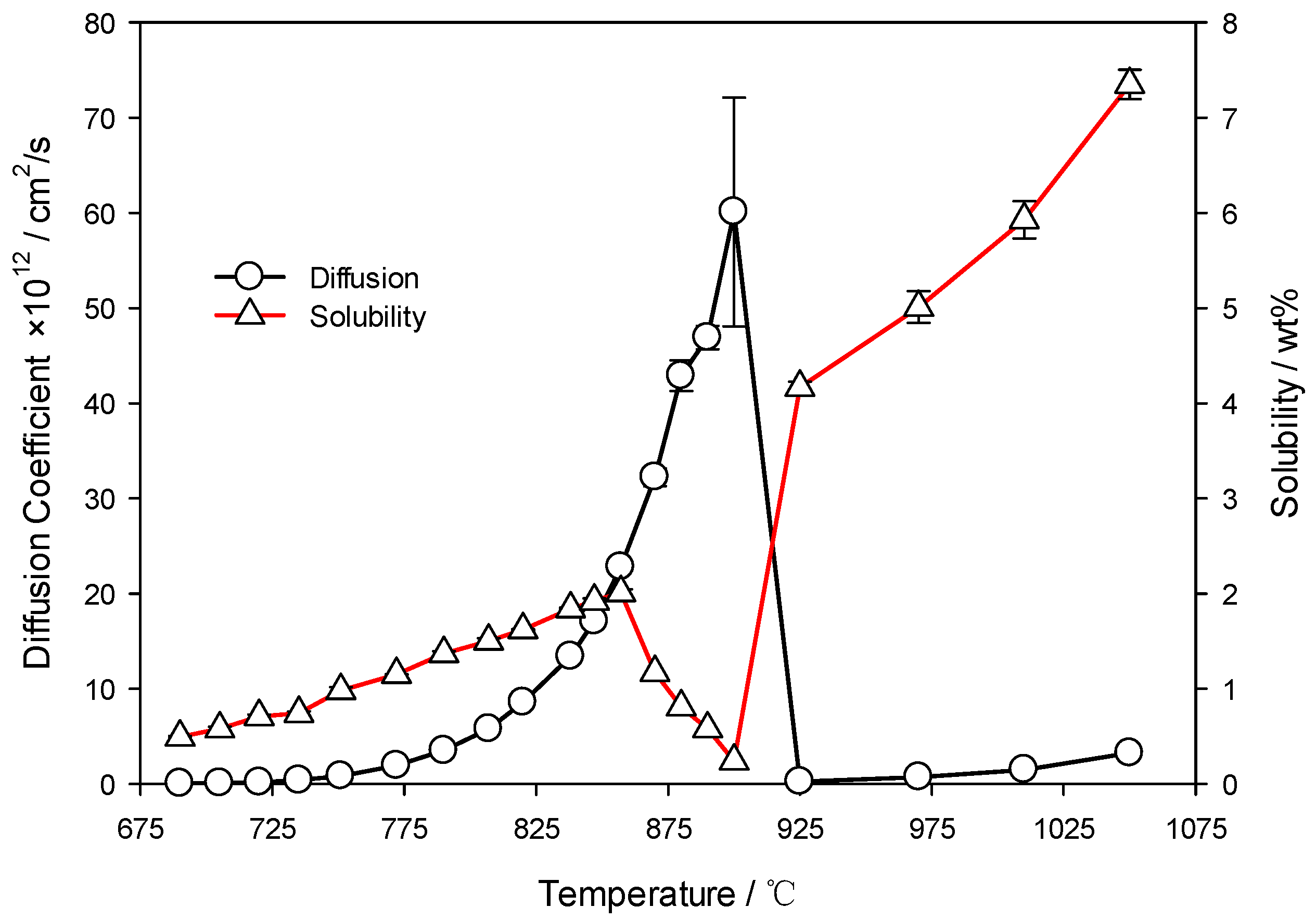
G. Salje et al. [17] systematically studied and summarized the dissolution and diffusion behavior of Cu in Fe. The solubility and diffusion coefficients of Cu in Fe at different temperatures are shown in Figure 9.
It can be seen from Figure 9 that when the temperature is higher than 925 °C, although the solubility of Cu in Fe is high, reaching more than 4%, the corresponding diffusion coefficient of Cu in Fe is extremely low. For continuous casting, the temperature of the billet is above 900 °C during the operation of the continuous caster, which makes it difficult for the Cu accumulated in the grain boundary to diffuse into the steel matrix and form the copper-rich phase on the surface of the billet. The probability of crack formation along the grain boundary, i.e., copper-rich phase, increases significantly for billets requiring bending and straightening deformation.
When the steel is in the austenite temperature range, the diffusion coefficient of Cu in Fe is large, but the solubility of Cu in Fe is very low, which is not conducive to the uniform diffusion of Cu in steel. Further, only when the billet is out of the caster is the temperature likely to leave the austenitizing temperature range, but at this time the surface cracks have been generated. In addition, the low solubility of Cu in steel makes it easier for Cu to accumulate in the micro-defects of steel. At this time, the diffusion of Cu cannot eliminate cracks, and the uneven diffusion of Cu into the steel matrix will further aggravate the propagation of cracks on the surface of slab during rolling.
5. Conclusions
After the contact wear between the copper layer and the casting billet, the worn copper will remelt when it is attached to the surface of the casting billet. At this time, in addition to the diffusion of Cu on the surface of the steel, Fe in the steel will also begin to dissolve in the copper liquid, which improves the melting point of the copper liquid and accelerates the solidification of the copper liquid, and forming a stable fusion bonding between copper and steel. When the temperature is 1100 °C and the hot-dip coating is 60 s, the load of the sample before fracture exceeds 700 n, indicating that the bonding strength of the copper–steel transition layer is great. Due to the enrichment of the Fe-C phase and a large number of vacancies at the grain boundary of the steel, the Cu initially combined with the steel matrix is more likely to accumulate at the grain boundary. Moreover, because the continuous casting temperature is higher than 900 °C, the Cu at this time has a high solubility in Fe, which can reach more than 4%, but the diffusion coefficient is very low, which makes it very difficult for the Cu accumulated at the grain boundary to diffuse into the steel matrix during the whole continuous casting process, and forms a copper-rich phase on the surface of the slab, leading to the formation of surface cracks in the bending and straightening deformation of the slab.
Author Contributions
J.Z. conducted the research and results analysis under the supervision of L.Z., L.S. and P.X. contributed to the design of the experiments and the morphology analysis during the research activities, and B.W. contributed to the image processing and data calculation. All authors have read and agreed to the published version of the manuscript.
Funding
This work was supported by the National Natural Science Foundation of China (Grant Numbers: 51804125, 51904107, and 52004093) and the Fundamental Scientific Research Business Expenses of Colleges and Universities in Hebei Province (Grant number: JQN2021017, BJ2019041).
Conflicts of Interest
The authors declare no conflict of interest.
References
- Cai, K.K.; Cheng, S.F. Principles and Processes of Continuous Casting Steel; Metallurgical Industry Press: Beijing, China, 2007. [Google Scholar]
- Geng, M.S.; He, K.N.; Zhang, J.M.; Wang, X.H.; Xiao, J.G. Study on surface micro cracks on medium plate. Iron Steel 2008, 43, 80–83. [Google Scholar]
- Yang, C.F.; Su, H.; Li, L.; Zhang, Y.Q. Enrichment of Cu, Ni in surface oxidation layer of copper-bearing age hardening steel. Iron Steel 2007, 42, 57–60. [Google Scholar]
- Yang, H.X.; Yang, H.; Zhao, Y.L.; Liu, J.; Ge, J.J.; Ren, L.L.; Yu, Q.X.; Yu, J.Z. Cracking analysis and control measures for pressure vessel steel. Heat Treat. Met. 2017, 42, 187–191. [Google Scholar]
- Huang, Y.; Du, J.L.; Wang, Z.M. Progress in research on the alloying of binary immiscible metals. Acta Metall. Sin. 2020, 56, 801–820. [Google Scholar]
- Bachmaier, A.; Kerber, M.; Setman, D.; Pippan, R. The formation of supersaturated solid solutions in fe–cu alloys deformed by high-pressure torsion. Acta Mater. 2012, 60, 860–871. [Google Scholar] [CrossRef] [PubMed] [Green Version]
- Li, P.H.; Bao, Y.P.; Yue, F.; Peng, Z.; Wu, H.J. Effect of abnormally large prior-austenite grains on the presence of surface intergranular cracks. J. Univ. Sci. Technol. Beijing 2009, 31, 177–181. [Google Scholar]
- Imai, N.; Komatsubara, N.; Kunishige, K. Effect of Cu, Sn and Ni on hot workability of hot-rolled mild steel. ISIJ Int. 1997, 37, 217–223. [Google Scholar] [CrossRef] [Green Version]
- Sun, Y.; Zhao, Y.; Zhao, B.; Guo, Z.; Hou, H. Multi-component phase-field simulation of microstructural evolution and elemental distribution in Fe–Cu–Mn–Ni–Al alloy. Calphad 2020, 69, 101759. [Google Scholar] [CrossRef]
- Messina, L.; Schuler, T.; Nastar, M.; Marinica, M.C.; Olsson, P. Solute diffusion by self-interstitial defects and radiation-induced segregation in ferritic Fe-X (X=Cr, Cu, Mn, Ni, p, Si) dilute alloys. Acta Mater. 2020, 191, 166–185. [Google Scholar] [CrossRef] [Green Version]
- Xu, T. Interfacial Segregation and Embrittlement. In Reference Module in Materials Science and Materials Engineering; Elsevier: Amsterdam, The Netherlands, 2016. [Google Scholar]
- Liu, S.X. Practical Metal Materials Handbook; China Machine Press: Beijing, China, 2017. [Google Scholar]
- Wang, T.; Zhao, Y.L.; Chai, L.T.; Xu, Q.; Sun, L. Influence of hot dip process on aluminum silicon coating for hot forming steel. China Metall. 2016, 26, 20–25. [Google Scholar]
- Xiong, L.; Chen, W.; Guo, W.; Fu, Q.F.; Lu, D.P.; Yi, G.B.; Jing, Y.H.; Luo, L.; Liu, Y. Effect of C addition on the liquid phase separation in an as-cast Cu–14Fe alloy. Materialia 2019, 7, 100379. [Google Scholar] [CrossRef]
- Pan, J.S.; Tong, J.M.; Tian, M.B. Foundation of Material Science; Tsinghua University Press: Beijing, China, 2011. [Google Scholar]
- Toshiyuki, K.; Masamitsu, W.; Naoki, T.; Shigeaki, O.; Shozo, M. Influence of heating temperature and strain on surface crack in carbon steel induced by residual copper. Tetsu-to-Hagane 2009, 81, 185–190. [Google Scholar]
- Salje, G.; Feller-Kniepmeier, M. The diffusion and solubility of copper in iron. J. Appl. Phys. 1977, 48, 1833–1839. [Google Scholar] [CrossRef]
Figure 1.
Experimental equipment.

Figure 2.
The microstructures of the Cu–steel interface with hot-dipping time of 60 s under different temperatures.
Figure 2.
The microstructures of the Cu–steel interface with hot-dipping time of 60 s under different temperatures.

Figure 3.
The microstructures of the Cu–steel interface with different hot-dipping times under 1125 °C.
Figure 3.
The microstructures of the Cu–steel interface with different hot-dipping times under 1125 °C.

Figure 4.
Changes in Cu and Fe elements of Cu–steel transition layer under different temperatures.

Figure 5.
The thickness of Cu–steel transition layer under different hot-dipping temperatures.

Figure 6.
The bounding strength of Cu–Steel interface.

Figure 7.
Cu-Fe binary phase diagram.

Figure 8.
Surface scan results of the steel substrate surface at the Cu–steel interface.

Figure 9.
The solubility and diffusion coefficients of Cu in Fe under different temperatures.

Publisher’s Note: MDPI stays neutral with regard to jurisdictional claims in published maps and institutional affiliations. |
© 2022 by the authors. Licensee MDPI, Basel, Switzerland. This article is an open access article distributed under the terms and conditions of the Creative Commons Attribution (CC BY) license (https://creativecommons.org/licenses/by/4.0/).
Share and Cite
MDPI and ACS Style
Zhou, J.; Zhu, L.; Sun, L.; Wang, B.; Xiao, P. Analysis of the Formation Mechanism of Surface Cracks of Continuous Casting Slabs Caused by Mold Wear. Processes 2022, 10, 797. https://0-doi-org.brum.beds.ac.uk/10.3390/pr10040797
AMA Style
Zhou J, Zhu L, Sun L, Wang B, Xiao P. Analysis of the Formation Mechanism of Surface Cracks of Continuous Casting Slabs Caused by Mold Wear. Processes. 2022; 10(4):797. https://0-doi-org.brum.beds.ac.uk/10.3390/pr10040797
Chicago/Turabian StyleZhou, Jingyi, Liguang Zhu, Ligen Sun, Bo Wang, and Pengcheng Xiao. 2022. "Analysis of the Formation Mechanism of Surface Cracks of Continuous Casting Slabs Caused by Mold Wear" Processes 10, no. 4: 797. https://0-doi-org.brum.beds.ac.uk/10.3390/pr10040797
Note that from the first issue of 2016, this journal uses article numbers instead of page numbers. See further details here.