
Coating Process of Honeycomb Cordierite Support with Ni/Boehmite Gels
by
 ,
,
Vincent Claude
1, 
Julien G. Mahy
1,2,*,
Timothée Lohay
1,
Jérémy Geens
1 and
Stéphanie D. Lambert
1,2,* 1
Department of Chemical Engineering—Nanomaterials, Catalysis, Electrochemistry, B6a, University of Liège, 4000 Liège, Belgium
2
Fonds de la Recherche Scientifique (FNRS), Rue d’Egmont 5, 1000 Bruxelles, Belgium
*
Authors to whom correspondence should be addressed.
Processes 2022, 10(5), 875; https://0-doi-org.brum.beds.ac.uk/10.3390/pr10050875
Submission received: 21 March 2022
/
Revised: 14 April 2022
/
Accepted: 27 April 2022
/
Published: 28 April 2022
(This article belongs to the Special Issue Advances in Sol-Gel Processes)
Abstract
:This study presents the development of a method for the washcoating of Ni/boehmite gels, prepared by the sol–gel process, onto the surface of a commercial ceramic monolith. Indeed, a cordierite monolith in a honeycomb shape was used as the substrate for the Ni/Al2O3 deposition. An experimental assembly was made in order to apply the coating on the cordierite surface. Different suspensions were used with various viscosities, and multiple coating parameters were tested as the withdrawal speed, or the number of impregnations. It was observed that the simple deposition of the Ni/boehmite gel led to the formation of coating. Different morphologies were observed, and defects were highlighted as cracks, coating-free areas or aggregates. Among the various parameters studied, the pH of the sol appeared to play a role even more important than the viscosity. Indeed, the sol acidified with nitric acid showed a coating which was almost free of cracks or of large aggregates. Moreover, the use of a slurry mix of calcined alumina particles and colloidal boehmite appeared also as an interesting path. The beneficial influence of the slurry was attributed to a better resistance of the coating against the stresses induced during drying, and a deviation of the cracks in the gels by slurry grains.
1. Introduction
Monolithic catalytic reactors are part of a broad category of structured catalysts. Monoliths can be described as bunches of parallel channels of square-shaped cross sections, though triangular, hexagonal, corrugated or circular shapes are also common. Each of these channels constitutes by itself a sub-reactor because no mass transfer can occur from one channel to another. A fluid flows through the channels and comes in contact with the catalytically active phase, which may either be the monolith itself or a coating. Monolithic supports can be made of either metal or ceramic. Metallic monoliths are produced by the corrugation of a metal sheet, whereas ceramic ones are extruded and fired at a high temperature (>1000 °C) [1]. Only ceramic monoliths are used in this study.
The use of monolithic reactors has different advantages/disadvantages in comparison to packed-bed reactors, whose catalytic phase spatial arrangement does not exhibit any geometrical regularity or symmetry. Among these particularities, one can retain (i) the low-pressure drop associated with a laminar flow of the reaction mixture within the straight channels of the monolith; (ii) an almost impossibility to plug the channels—however, fouling can occur by impaction of dust particles or by coking against the channel walls; (iii) the ease of scaling-up; (iv) the absence of attrition in the active phase; (v) the high surface-to-volume ratio [2,3,4,5,6,7].
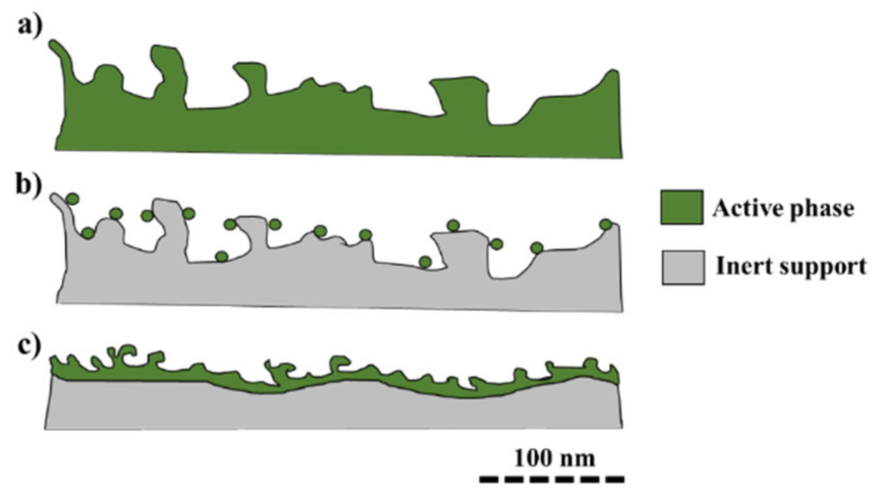
The ceramic monoliths used in catalysis are classified according to the porous properties of the constitutive material and of the method of incorporation of the active phase (Figure 1) [8,9].
Integral monoliths (Figure 1a) are partially or entirely made out of the active phase. They are usually formed from a paste, which is either molded or extruded, and then fired at high temperature (T > 1000 °C) [8,9]. High-surface monoliths (Figure 1b) show a well-designed porous structure (specific surface of a few hundreds of m2/g), over which precursors of the active phases (usually salts) can be directly deposited by impregnation. However, these supports show low mechanical strengths [10]. Low-surface monoliths (Figure 1c) show a low specific surface (<10 m2/g), but present higher mechanical strength. The purpose of the low-surface monolith is to be a support for the deposition of a high-surface coating. The coating material can either be a commercial high-surface catalyst or a highly porous support phase, such as mesoporous γ-alumina or colloidal boehmite [11,12,13]. The active phase can be either contained inside the coating phase or impregnated thereafter on the high-surface-area layer.
In this study, low-surface monoliths were produced from Ni/boehmite-based catalyst suspensions. Low-surface monoliths give a high mechanical strength to the produced catalysts. Commercial cylinders of cordierite with square-shaped cross sections were used. Cordierite material (2Al2O3·2MgO·5SiO2) is commonly used as a monolith support in the catalyst field [14,15,16,17].
Ni/boehmite-based catalysts can be used in tar removal [18,19,20,21,22]. Indeed, Ni catalysts can be supported on many substrates as Al2O3, ZrO2, SiO2, Zeolites or Olivine [18,19,20,21,22].
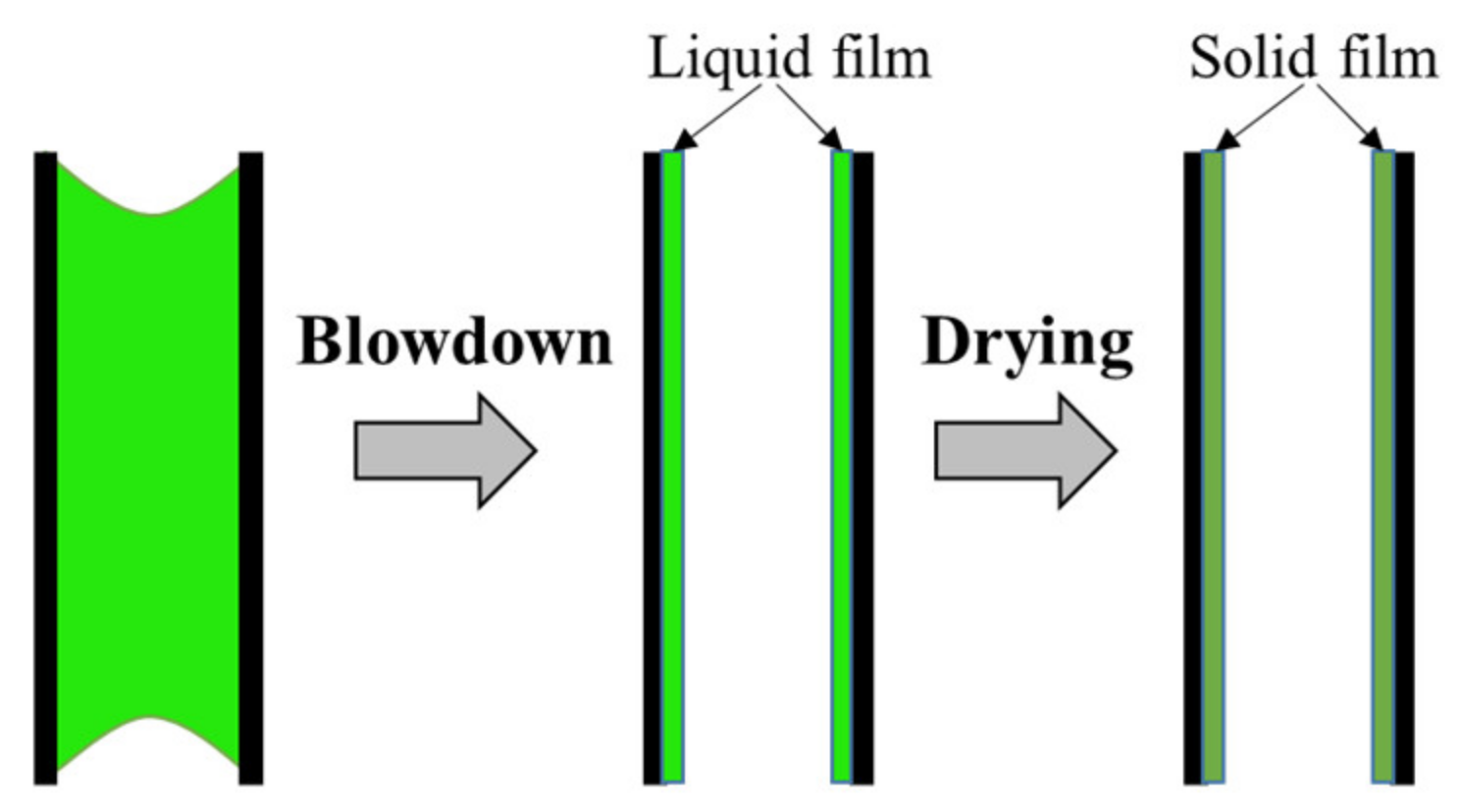
To produce the coating, a suspension of catalytic materials must be prepared. The coating precursor phase is either a powder slurry or a sol that undergoes gelation in the channels of the monolith [12]. The premises of monolith coating were established by Taylor [23] for the coating of cylindrical capillaries, extending the work of Fairbrothers & Stubbs [24] to a greater range of experimental conditions. The method developed by the authors, known as gas–fluid displacement, consisted of sending a gas flux into a previously filled glass capillary. As the bubble of gas crossed the capillary at a given speed, it drives out a fraction of the liquid and leaves the remaining as a film. A few decades later, Kolb & Cerro [25] devised a similar method to coat porous square-channeled monoliths. The coating was performed in three steps: filling of the channels by dip; removal of the liquid with a blowdown step; and drying (Figure 2). The blowdown step allows the formation of a film whilst pre-drying it, thus preventing the appearance and growth of instabilities in the liquid coating film [26].
The thickness and quality of the deposited layer depends on two simultaneous mechanisms: (i) the mechanism of filter–cake formation, which consists in the selective absorption of the solvent by capillary suction into the porous monolith walls, leaving behind a concentrated layer of particles that may gel if the concentration of particles exceeds a critical value [11]. The name “filter” comes from the fact that the support acts the same way as a classical filter used to recover a solid from a colloidal solution; (ii) the mechanism of viscous adhesion, which is defined by the remaining of a liquid film on the monolith walls after the blowdown step. The film thickness depends on the purging gas velocity and on the viscosity of the coating solution [11,26]. A similar system was used in this study.
Once a solid film is deposited, it must adhere strongly enough to the monolith walls to prevent spalling during operation. Coating adhesion is mainly the result of anchoring and interlocking of the washcoated gel with the support surface irregularities and porosity. In comparison, the chemical affinity between the support and the coating is, apparently, asserted to play little role [27].
This study presents the development of a method for the washcoating of Ni/boehmite gels (prepared by the sol–gel process) onto the surface of a ceramic monolith. Indeed, from the economic and technical points of view, it is common to use a catalyst made of an inert ceramic support coated with an active phase [28]. The development of an effective washcoating method in the laboratory would therefore allow the use of the catalysts designed at larger scale. An experimental assembly was made in order to apply the coating on the surfaces of a commercial honeycomb monolith made of cordierite. Different compositions of Ni/alumina sols were used. The obtained materials were characterized by electronic microscopy. Hence, the influences of the composition of the coating solutions (type of solvent, concentration, acidity, slurry and sol + slurry) and of the procedure variables (withdrawal speed, number of impregnations, blowdown step and impregnation with a syringe) are investigated in order to optimize the quality of the deposited film.
2. Materials and Methods
2.1. Properties of Monolithic Support
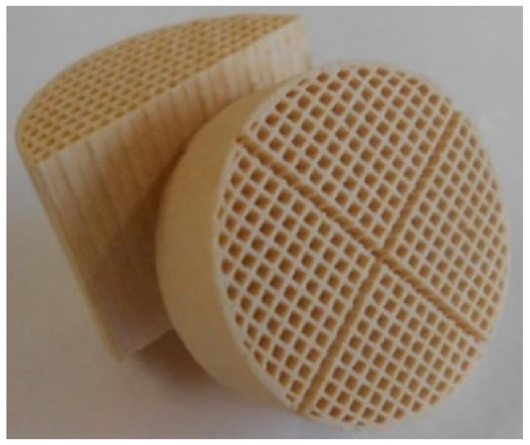
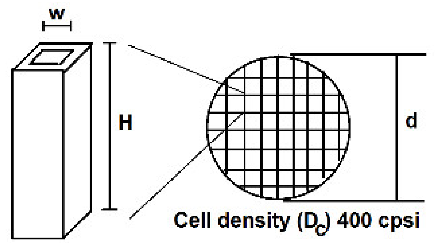
The support is shown in Figure 3. The cylinder cordierite monolith was furnished by the CTI SAS enterprise. Its cell density was of 400 cpsi (62 cells/cm2). The diameter of the cylinder was determined as 26 mm ± 1 mm. The channels were square-shaped with an inner width of 1 mm and the cordierite wall thickness was roughly of 0.275 mm. The cylinder was sliced into different parts of 0.96 cm for the impregnations. Hence, the surface-to-volume ratio of the monoliths was 31.5 for an open frontal area (OFA) of 61%. The OFA is the clear cross section surface available for the flow of the reaction mixture.
Nitrogen adsorption–desorption measurements (Supplementary Materials Figure S1) revealed that the support did not present any micro/mesoporosity (VDubinin < 0.001 cm3/g; Vp < 0.1 cm3/g) and had a very low specific surface area (SBET < 1 m2/g). Figure S2 shows a SEM–BSE picture of cordierite support. It can be observed that the support was macroporous with a wide pore size distribution, from a few µm to a ten of µm.
Thanks to mercury porosimetry (Supplementary Materials Figure S3), it is observed that most of the macropore sizes of the cordierite are between 1 and 20 µm. The macroporous volume, VHg,Cordierite was relatively small (0.30 cm3/g).
2.2. Ni Catalyst Suspension Preparation
Different suspensions were prepared for deposition on cordierite support with two main paths: (i) suspensions made from precursor solutions (Ni/boehmite suspensions); and (ii) suspensions made from pre-calcined-Ni/Al2O3 nanoparticles.
For the precursor suspension, the synthesis is as follows [18]:
Aluminum(III) nitrate nonahydrate Al(NO3)3·9H2O was dissolved in a deionized water/ethanol 3:1 mixture in a bottle under stirring. Amorphous aluminum hydroxide [Al(OH)3]n was precipitated at room temperature by dropwise addition (1 mL/min) of aqueous ammonia NH4OH (30 wt. %) until a pH of 9.5 was reached. The precipitate was aged at 85 °C in an oil bath and boehmite nanocrystallites were obtained within 24 h. They were washed two times with deionized water by centrifugation (8000 rpm for 15 min) to remove NH4+. Indeed, mixed with NO3− from the metallic salt, they could lead to the formation of explosive ammonium nitrate upon drying. The hydrated solid recovered was then redispersed in deionized water in a bottle. When the agglomerates have been broken under stirring, nickel(II) nitrate hexahydrate, Ni(NO3)2·6H2O, was added. The reference suspension (suspension A) of Ni/boehmite was obtained; some variations in the protocol provided different suspensions denoted in Table 1.
Then, for the suspensions made from pre-calcined-Ni/Al2O3 nanoparticles, the same steps were followed with these the following additional steps:
The bottle with precursor suspension was kept at room temperature under stirring for 30 min. Water was evacuated in an oven at 85 °C for 24 h at 700 mbar and a paste-like solid was obtained. Another drying step at 110 °C and 900 mbar for 24 h led to complete removal of the absorbed water and consecutive gelation between the boehmite crystallites. Nickel ions were supposed to be adsorbed on the colloidal boehmite. Calcination under air at 550 °C for 5 h transformed boehmite into γ-alumina and yields nickel oxide. Then, the powder was mechanically crushed to below 45 µm and dispersed in water to produce the suspension G (Table 1). The reference concentration was set to 50 g/L.
2.3. Coating Production
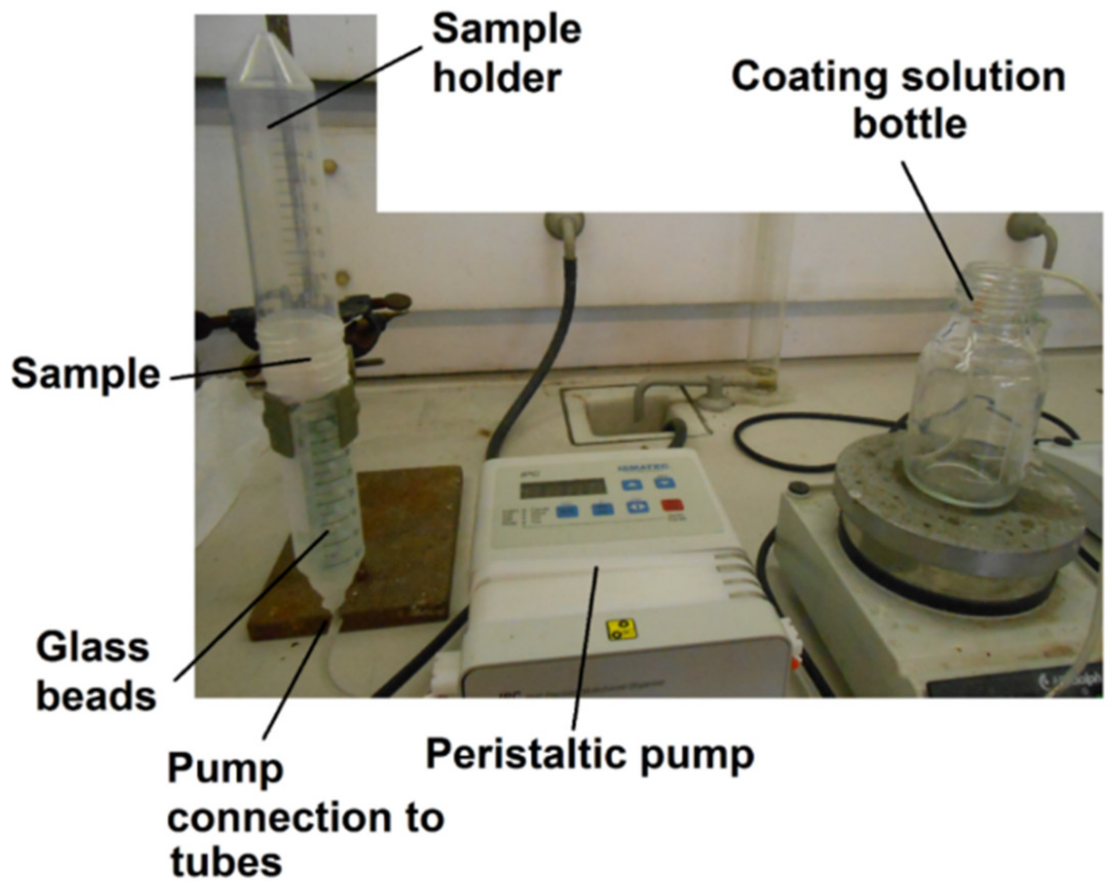
Figure 4 shows the experimental apparatus used for the preparation of cordierite supports coated with Ni/boehmite sols.
The coating apparatus consisted of two joined plastic tubes of a diameter slightly larger than the cordierite samples, so that the cordierite cylinders could be made to fit by surrounding their outer border with Parafilm®. The coating solution was sent in the tubes via an ISMATEC IPC peristaltic pump and risen at 0.6 cm/min until the monolith was completely covered. The pump was then stopped and after 2 min, the liquid was pumped back to the coating solution bottle. Clean glass beads were added to the bottom tube in order to reduce the dead volume and speed up the process. Finally, the monolith sample was carefully removed and dried from its top and bottom face at 85 °C and 700 mbar for 24 h.
Table 2 presents the different coating procedures investigated for sample A and the corresponding names of the resulting samples. The samples B to H were deposited with the classical parameters.
Prior to coating, the monoliths were cleaned in diluted nitric acid (1 M) for 30 min, followed by thorough washing with water and acetone, and a drying step at 120 °C for 2 h. The solid content of the coating solutions was equal to 5 g of calcined 10 wt. % Ni/γ-Al2O3 per 100 mL, except for the sol of the sample B, for which the amount of solid content was set to 2.5 g. In the case of sample 2A, the support was impregnated, dried for 2 h, and then submitted to a second impregnation.
2.4. Characterizations
Nitrogen adsorption–desorption isotherms were measured at −196 °C on a Micromeritics ASAP 2010 instrument after 12 h of outgassing at 300 °C and 10−5 Pa. The total specific surface area (SBET, m2/g) and mesoporous surface area (Smeso, m2/g) were determined by the Brunauer–Emmet–Teller (BET) theory on the part of the nitrogen adsorption curves for p/p0 values from 0.05 to 0.3. The Dubinin volume (VDubinin, cm3/g) corresponds to the sample microporous volume and was calculated using the Dubinin–Raduskevitch model [29,30]. The pore volume at saturation pressure (Vp, cm3/g) and the pore size distributions were determined by a home-made informatic program, which applied the Broekhoff–de Boer theory (BdB) to the adsorption profile branch of the nitrogen isotherms. The pore volume density is defined by the pore volume (cm3/g) as a function of the pore size (nm).
Mercury porosimetry measurements were performed on monolith samples crushed to between 300 and 700 µm using a Poremaster60 instrument from Quantachrome with pressures ranging from 1 to 60,000 Psi. The measurements permitted the determining of the macroporous volume (VHg, cm3/g), to plot the curves of volume introduced as a function of the pressure and to plot the macropore size distribution.
Viscosity measurements were performed on a DV-2+ Pro Brookfield viscometer at 10, 20, 50 and 100 rpm on an S61 or S62 spindle to ensure that the measured torque was superior to 10%. Solutions were poured into a 100 mL graduated cylinder to allow immersion of the spindle to the required level. To avoid border effect, the spindle was also placed at the center of the graduated cylinder. The measurement consists of the rotation of a spindle at a fixed speed in a fluid and the measurement of the amount of torque required to maintain the speed as viscous forces impede the rotation. It translates into the torsion of a spring inside the apparatus, proportional to the fluid viscosity. Apparent viscosity (shear stress divided by shear rate, expressed as mPa·s or centipoise, cP) was then recorded.
Point of zero charge (PZC) measurements were performed by powder addition method by adding crushed cordierite or 1 mL of the suspension to 10 mL flasks filled with deionized water, with a pH adjusted between 1 and 12 with NaOH and HCl. The flasks were stirred for 2 h and the pH was measured. As the hydroxyl surface groups of the powder protonate and deprotonate, the number of protons within the solution decreased or increased and the final pH changed. The hydroxyl surface groups of the powder assumed the role of a buffer, and providing sufficient surface groups were available, the solution reached equilibrium. On a plot of initial pH versus final pH, a plateau value is observed and corresponds to the PZC point.
The Dynamic Light Scattering Apparatus used was a Viscotek 802 DLS instrument. The sols were diluted 30× in MilliQ water and put on ultra-sound for 5 min in order to eliminate the presence of air bubbles. Dynamic light scattering (DLS) allows the obtaining of the particle hydrodynamic size distribution of the suspensions.
Scanning Electron Microscopy measurements were performed with a FEI ESEM-FEG XL3 device. The measurements were performed at an acceleration voltage of 15 keV, set on the Spot 4 and with a vacuum of 0.4 Torr. No previous metallization of the samples was necessary.
3. Results and Discussion
3.1. Properties of the Suspensions
3.1.1. Suspension A
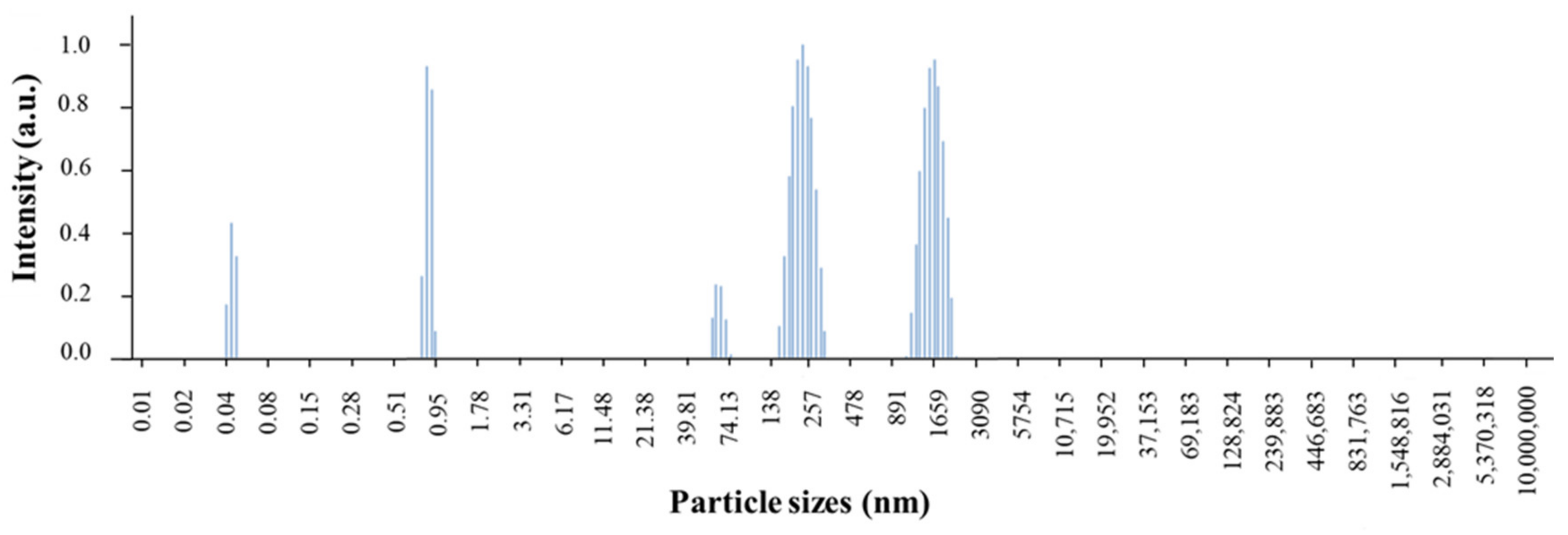
Figure 5 presents the particle size distribution of the reference suspension of Ni/boehmite (sample A, Table 1). It was observed that the major part of the boehmite grains sizes were either about 250 or 1500 nm.
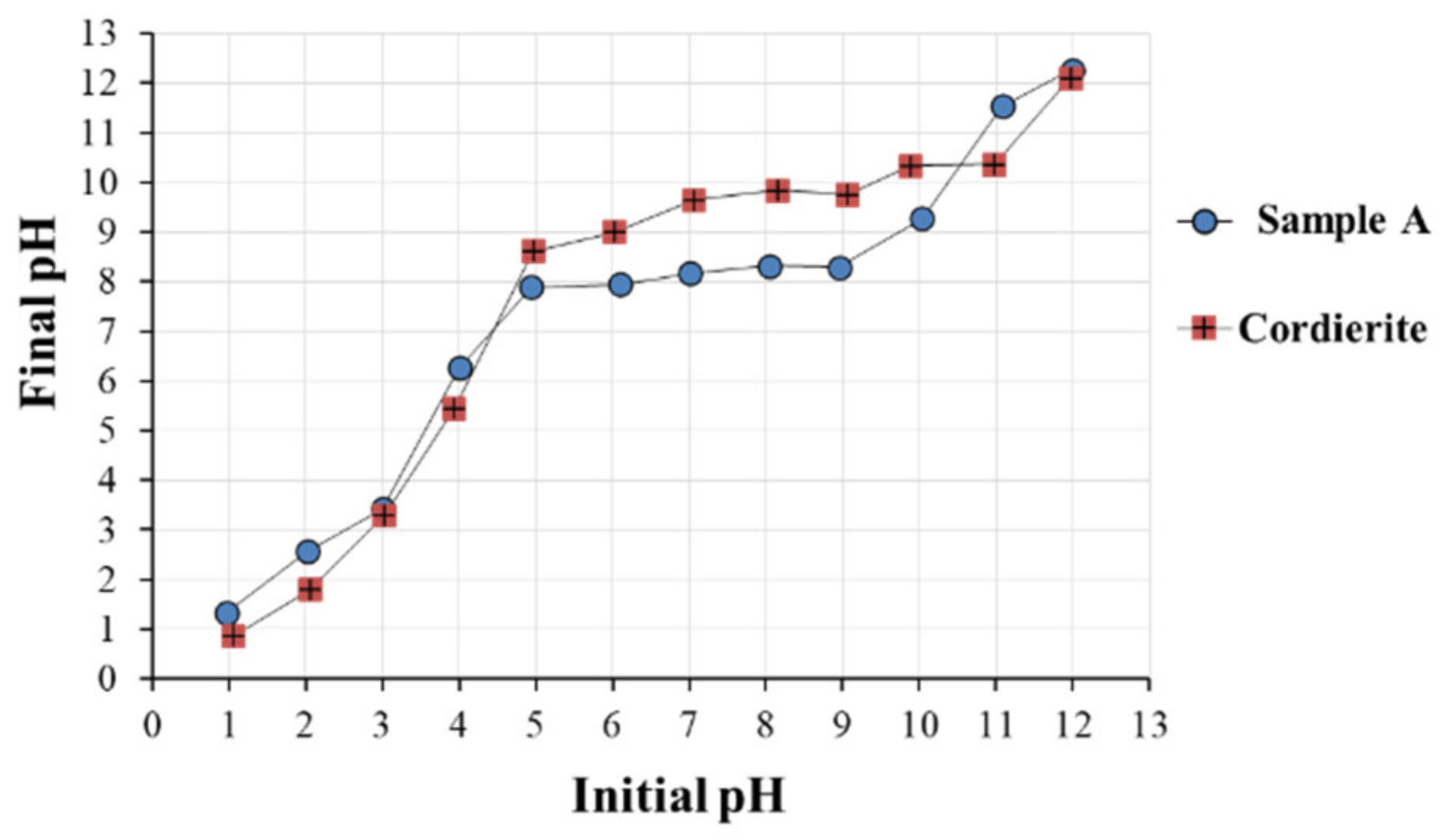
PZC measurements were carried out using the powder addition method to highlight potential electrostatic interactions between suspension A and the cordierite monolith. The PZC of cordierite was around 9.8, whereas it was around 8.1 for the Ni/boehmite sol (Figure 6). For information, the pH of a freshly prepared Ni/boehmite sol was equal to 6.7. Hence, the particles of boehmite were positively charged and were therefore theoretically able to be adsorbed on the basic surface of cordierite.
3.1.2. Modified Suspensions (B to H)
The composition of the standard Ni/boehmite sol (sample A) was modified according to different parameters. Table 1 presents the different parameters investigated, their corresponding samples names, and the viscosity of the sols measured at 10 rpm. In the case of sample C, the sol was paste-like and unsuitable for coating.
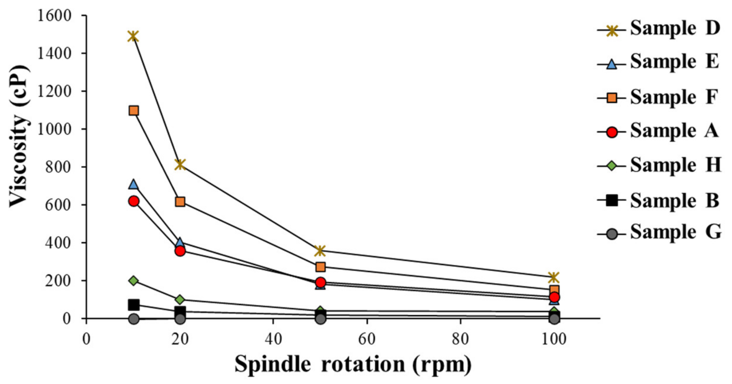
Figure 7 shows the viscosity of the different sols measured with rotating spindles and at different rotation speeds (10, 20, 50 and 100 rpm).
It can be observed in Figure 7 that, except for sample G, all the sols showed shear-thinning (i.e., non-Newtonian) behaviors, meaning that their viscosity values decreased under increasing shear strain. For example, the viscosity of sample A was measured to be equal to 630 cP at 10 rpm, but decreased to 110 cP when the rotation speed was set at 100 rpm. This rheological property can be explained by the interactions between the particles, which can form micron and submicron-sized agglomerates, as evidenced by the DLS measurement (Figure 5). These agglomerates are destroyed upon stirring, but reassembles as soon as stirring strength is decreased [31,32].
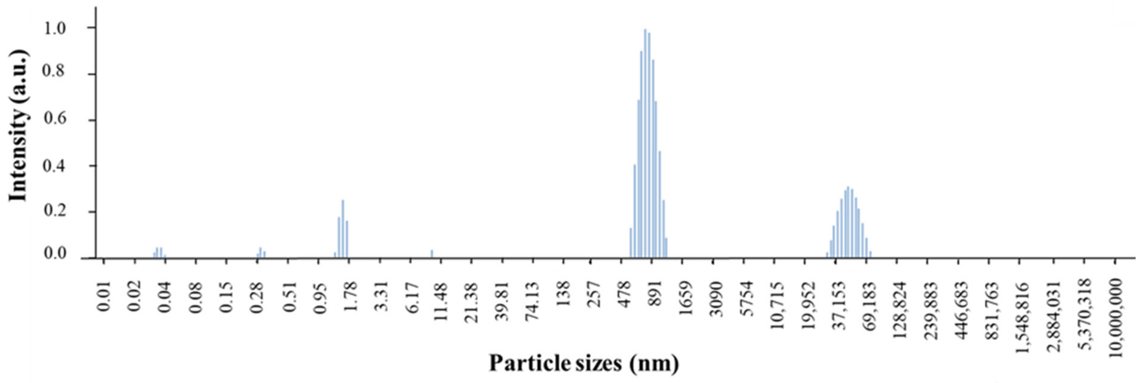
In the case of sample G, DLS measurement (Figure 8) showed that the slurry was mostly composed of grains of either about 800 nm or 5 μm. This information was important since it has been shown in the literature that coatings performed with slurry and slurry/boehmite sols should be performed with calcined alumina particles whose diameters are 5 μm maximum [33]. The very low viscosity (magnitude of the viscosity of water, ~1 cP) observed for this sample (Figure 7, Table 1) was attributed to the very few interactions existing between the calcined γ-Al2O3 particles of the slurry [11].
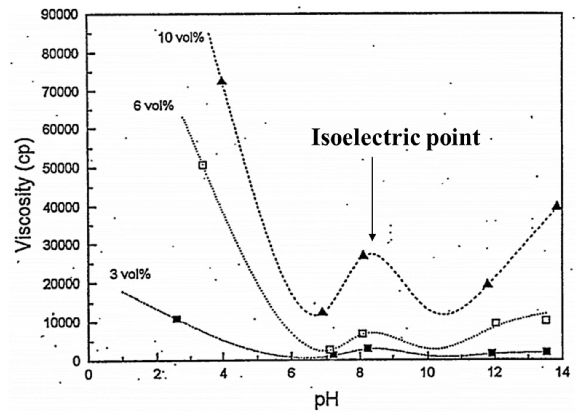
The addition of nitric acid, down to a pH of 1.8, for the coating solution of sample D, resulted in an increase in viscosity compared to sample A (Figure 7 and Table 1). Figure 9 shows the typical behavior of the viscosity of a boehmite solution as a function of pH [34]. At high acidic or basic pH (sample D), the viscosity is increased due to the presence of strong, long-range particle–particle repulsions [32,34]. Then, when the pH is moderately acidic or basic, the viscosity goes through minima because of lower repulsion forces between the particles (sample A). As the pH of the boehmite sol comes closer to the isoelectric point (typically a pH of 8–9, in the present case 8.1), the suspended particles are no longer repulsed but instead they flocculate, which greatly increase the viscosity of the sol [32].
It was observed in Figure 7 that the viscosities changed with the nature of the solvent in this increasing order: A < E < F. This was attributed to two reasons: (i) the dielectric constant values of ethanol and acetone are much lower than water (εWater,25°C = 80.1 > εEthanol,25°C = 25.1 > εAcetone,25°C = 20.3) [35]. This could result in greater repulsion between particles of similar charges and consequently an increase in the viscosity [36]; (ii) the absolute viscosity value of the solvents are as follows: μEthanol,25°C = 1.09 cP > μWater,25°C = 0.89 cP > μAcetone,25°C = 0.30 cP [35], which would explain why, among the three solutions, sample F showed the highest viscosity.
In accordance with the literature [32], it was observed that the evolution of the viscosity of the sol with the concentration of Ni/boehmite was non-linear (Figure 7, Table 1). In the case where the gel concentration was multiplied by 2 (sample C), the sol was far too viscous for its viscosity to be measured, or to coat in on the monolith. In contrast, when the Ni/boehmite concentration was divided by 2 (sample B), the sol was much less viscous (viscosity divided by 8 at 10 rpm) (Figure 7, Table 1).
The presence of slurry particles increased the viscosity of the sol. Indeed, for a similar concentration of boehmite, sample H presented a viscosity of 200 cP at 10 rpm instead of 80 cP for sample B.
3.2. Control of the Coating Mass Deposition
Figure 10 shows the typical geometrical variables used to definite a honeycomb channel inside a monolith.
In order to check that the amount deposited was equal to the amount expected, the samples were weighted before the coating and after the drying steps. The theoretical mass load after calcination, mth, was calculated for each sample using Equation (1). It corresponds to the total amount of solid that should be found in the monolith after drying, considering that the whole channel volume was filled by the coating solution.
where mth is the theoretical mass load, Vch is the whole channels volume, Dc is the cell density, Amonolith is the monolith of cross section area and Csol,wt is the concentration of the coating solution.
Replacing Vchl by HW2 and Amonolith by π(d/2)2, Equation (1) becomes:
Csol,wt was set to 0.05 g/mL. H, W and d were respectively equal to 0.96 cm, 0.1 cm and 2.55 cm. Dc was equal to 62 cells/cm2.
According to TG-DSC measurements performed on these kinds of Ni/Al2O3 catalysts [18], the mass loss during transformation of boehmite to γ-Al2O3 is of 75%. Hence, the theoretical mass of boehmite obtained after coating and drying is:
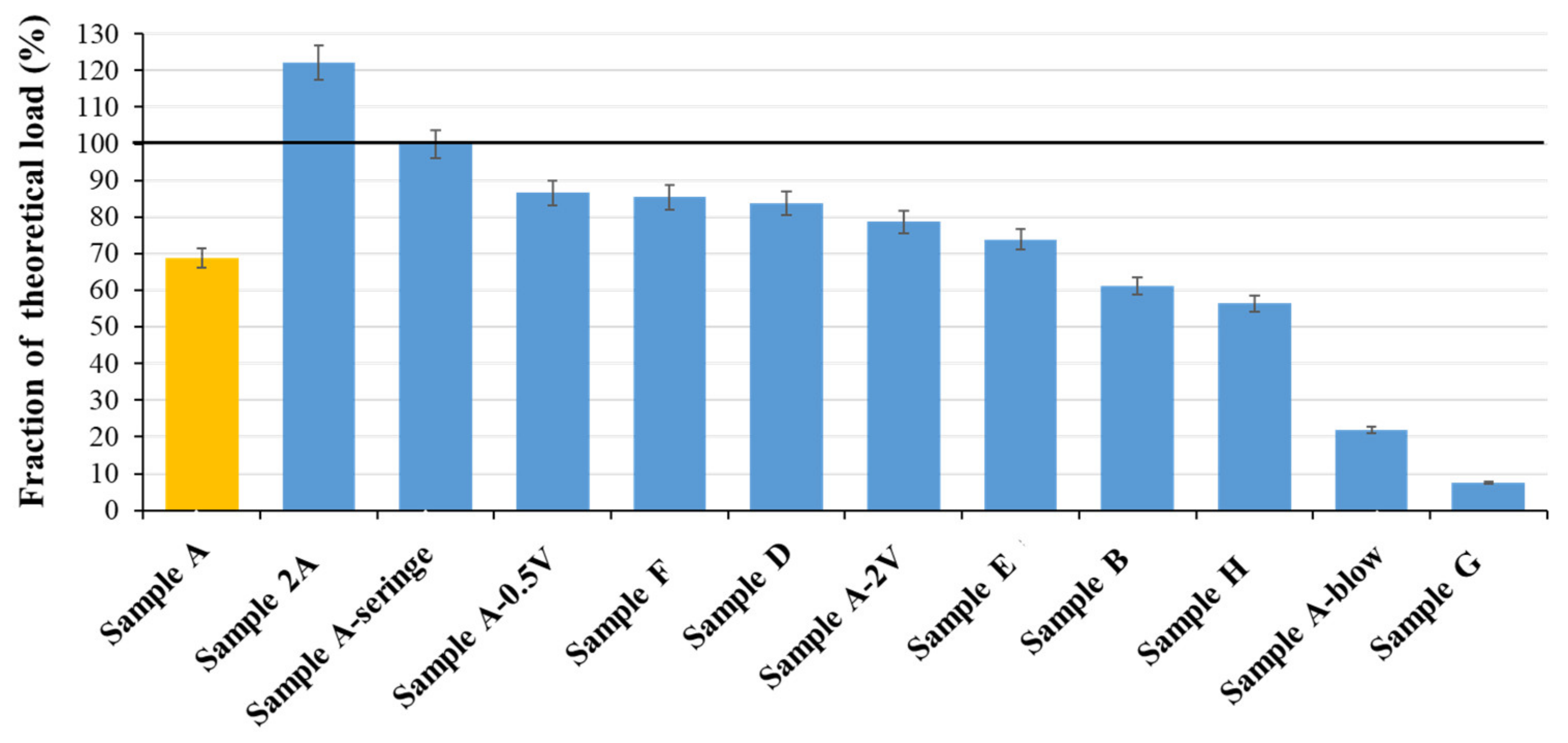
It was observed in Figure 11 that most of the coated monoliths presented differences between their theoretical and actual loadings after drying. These differences revealed some issues that occurred during the impregnation. For instance, sample A presented a coating mass of about 70% of the theoretical load. When impregnated a second time (sample 2A), the sample presented a higher mass (123%), but this value was still below the theoretical mass gain value (in case of twice doping: 200%).
It was suspected that the high viscosity of the coating solutions avoided their uniform penetration through the channels of the monolith. Indeed, it was observed that, at first, the coating solutions penetrated the sample only by a few channels, whilst the others may have been only partially filled. Aside from inhomogeneous filling of the channels by the coating solutions, the difference between the actual and theoretical coating mass deposited was also attributed to the presence of air bubbles trapped by the coating solution as the sol rose through the monolith channels. Evidence confirming this effect is presented in the next section.
The change in the withdrawal speed (samples A-0.5V and A-2V) did not have a visible influence on the mass of deposited coating.
Since ethanol and acetone show lower tension surface values compared to water (γEthanol ~ 0.022 N/m and γAcetone ~ 0.024 N/m, whereas γWater ~ 0.073 N/m) [37], one could have expected that it would have promoted the capillary filling of the channels. However, as these samples also showed high viscosity values (Figure 7, Table 1), it could explain why these samples also showed lower mass deposits (Figure 11).
The low mass deposit observed for sample A-blow is attributed to the nitrogen flux causing the evacuation of a part of the sol from the channels (Figure 11).
In the case of samples B and G, it was assumed that the coating solutions had a too low viscosity to remain totally inside the channels when solutions were withdrawn. As a result, only a liquid film, whose thickness is a function of the coating solution viscosity, was deposited when the coating solution was withdrawn. Furthermore, as the particles of the slurry had very low interactions between each other, this would explain why sample G showed the lowest mass gain value (8%).
The correct mass deposit (99% of mass gain) obtained for the sample prepared by an individual filling of each channel with a syringe (sample A-Syringe) tends to confirm the assumption that the mass deficits were principally caused by an incomplete filling of the channels.
3.3. Aspects of the Coatings
SEM measurements were performed on each dried sample in order to get an overview of the aspects of the coatings. The following three main types of defects were observed: coating-free areas; large aggregates; and cracks. Table 3 lists the observations made on the 13 samples coated, varying the solution properties and the coating procedure parameters.
All the coatings prepared at different withdrawal speeds (samples A-0.5V and A-2V), with different solvents (samples E and F), and with a second impregnation (sample 2A) or with a filling of the channels by a syringe (sample A-Syringe), presented the typical defects observed for a standard impregnation (sample A), that is to say, coating-free areas, cracks and large aggregates.
The transformation of boehmite into γ-Al2O3 is known to be topotactic (no variation of volume) [38,39]. Hence, the formation of a homogeneous Ni/boehmite gel coating free of defects appears as the most critical step. This assumption was confirmed by the fact that SEM observations (not shown here) performed on a calcined coating of Ni/γ-Al2O3, prepared according to the standard impregnation method (sample A), presented similar aspects and defects as observed for the dried samples. For this reason, only the aspects of dried samples are described in the following parts.
3.3.1. Coating-Free Areas and Large Aggregates
Coating-free areas were observed for almost all the samples (Table 3). In the case of sample G, instead of a film, only isolated micron-sized slurry particles were present on the channel walls (Figure 12).
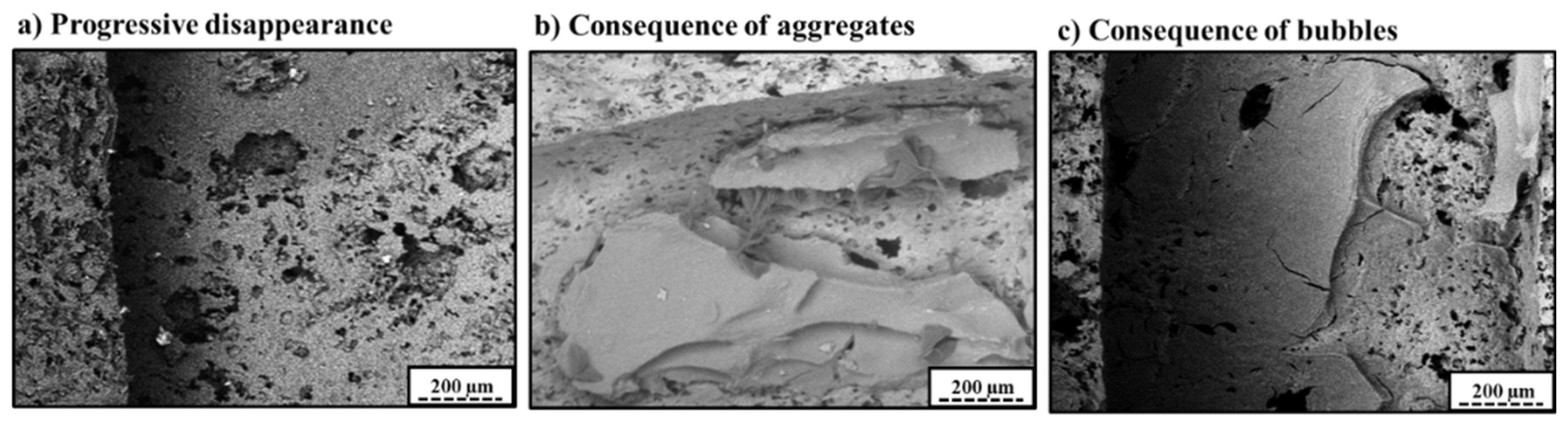
Figure 13 gives an overview of the three main aspects and reasons leading to the presence of coating-free areas.
The progressive disappearance (Figure 13a) of the coating in some areas was a consequence of an inhomogeneous repartition of the coating. According to the surface of monoliths available and to the theoretical mass deposited (determined in Section 3.2), the thickness of a homogeneous coating was expected to be at a maximum of 4.2 µm for a standard impregnation. In reality, in some areas, the coating was thicker than the theoretical value of 4.2 µm. Hence, in some other areas, it was thinner than 4.2 µm, sometimes to such an extent that there was no coating anymore. The progressive disappearance generally occurred in a gradual transition from thick to thin and, finally, to no coating. This behavior could be attributed to uneven drying, which tended to draw the coating solution to places where the evaporation was fastest, usually the outer rims [12,40]. Indeed, it was observed during SEM measurements that these coating-free areas were usually present at the center of the channels.
Figure 13b shows a typical example of a coating-free area caused by the formation of large aggregates. The formation of these large aggregates is believed to be caused by an insufficient anchoring of the gelating sol within the porosity of the cordierite support [27]. In this way, during the drying step, the shrinking gels are broken apart from the support and compacted into huge agglomerates.
Figure 13c shows a typical aspect of a circular coating-free area caused by the presence of bubbles. Indeed, during the impregnation, bubbles could be either within the cordierite porosity or in the coating solution.
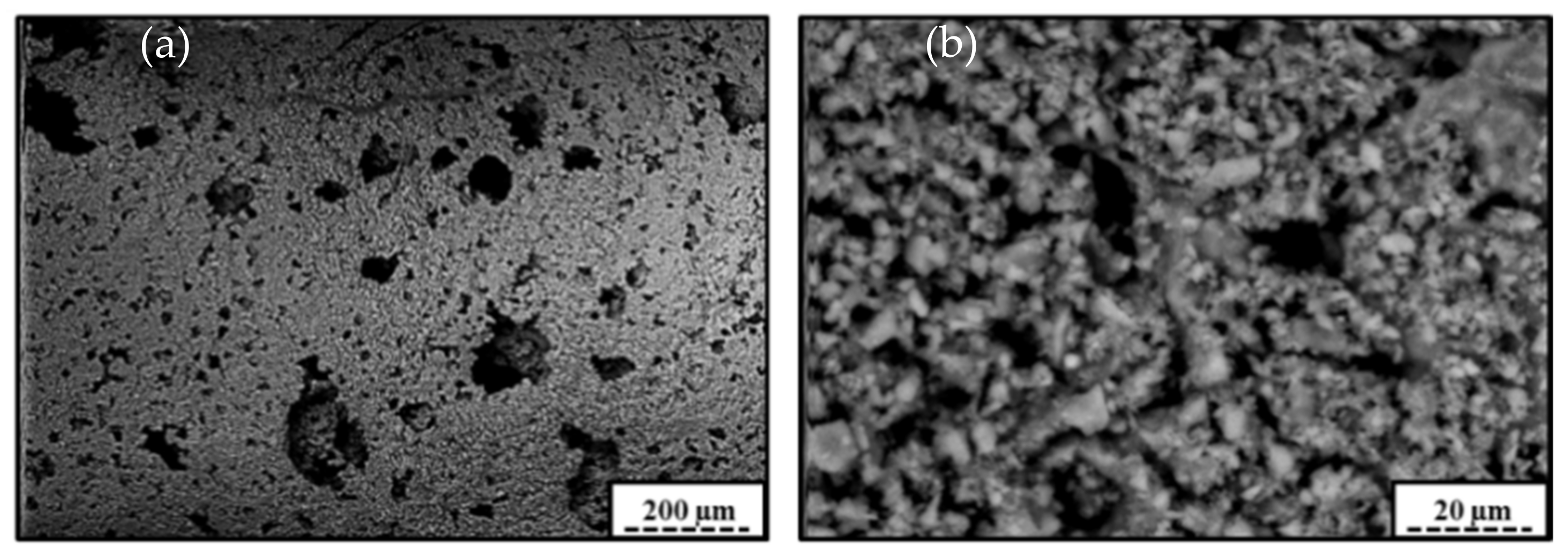
Sample A-Blown confirmed the positive influence of a blowdown step on the formation of homogeneous coating (Table 3). In that case, the flux permitted to prevent the formation of large aggregates and to eliminate the presence of bubbles. However, coating-free areas of the progressive disappearance type were observed, caused by a too high experimental blowing pressure. It is noteworthy that in some places where the coating film was homogenous, darker spots were visible during SEM–BSE measurements (Figure 14a). These darker spots were actually pores of cordierite filled with the Ni/boehmite gel. This fact was positive since a good anchoring of the gels within the support porosity is known to prevent the shrinkage of the gels, together with its associated undesirable consequences.
These darker spots were also observed for the solution acidified by nitric acid
(Figure 14b, sample D). Whereas this sample was the one presenting the highest viscosity value (Table 1), it presented a homogeneous coating, almost free of cracks and almost free of large agglomerates. This good aspect of the coating was attributed to the presence of strong repulsions between positively charged boehmite particles at a strongly acidic pH (Figure 6), which would permit the retention of a good dispersion of the particles and to prevent the aggregation of the coating in large aggregates [11,34].
3.3.2. Cracks
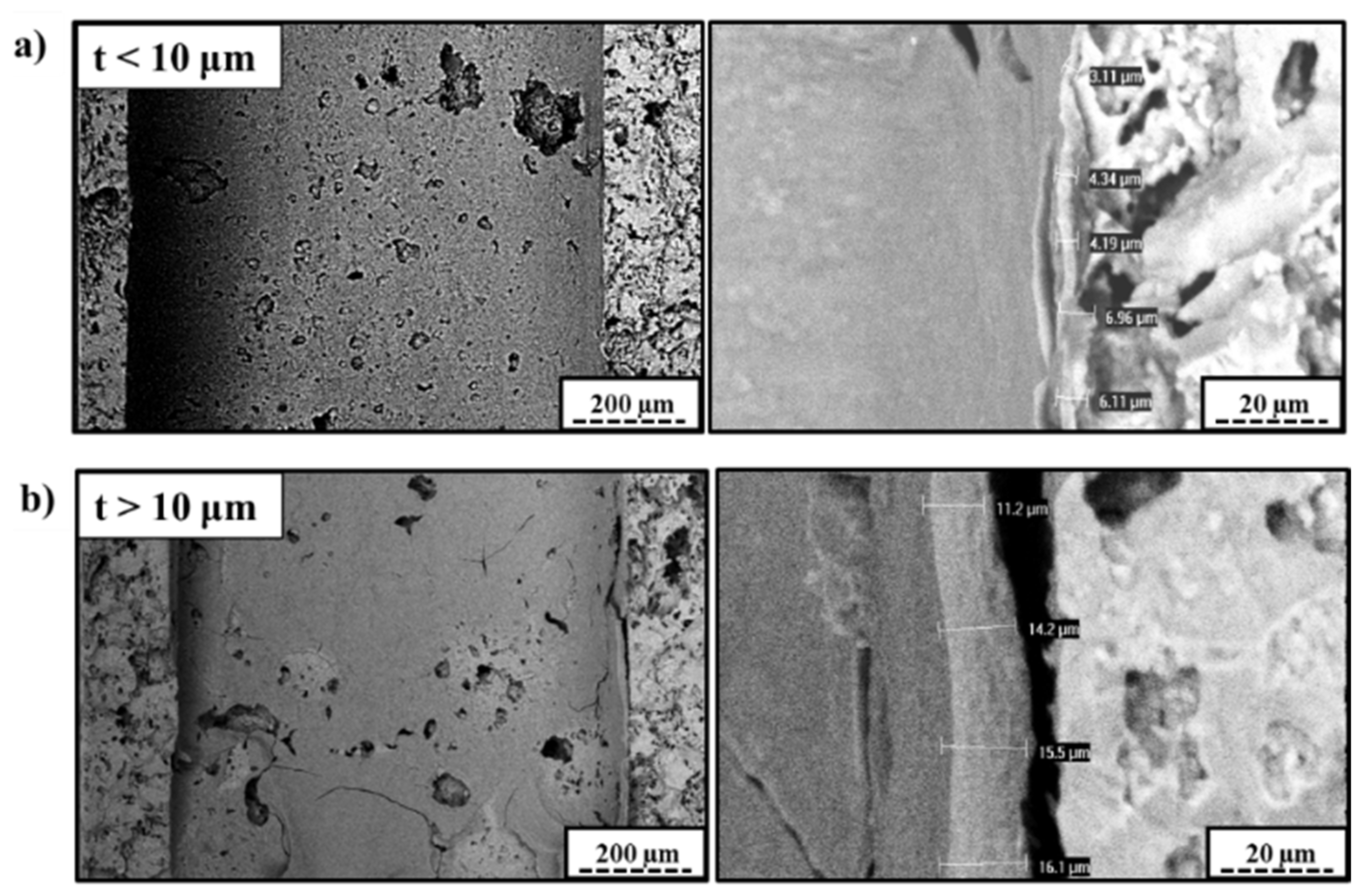
Cracks are thought to result from shrinkage-induced stresses in the gelating sol, mostly caused by non-uniform drying rates through the coating. Once the stresses reach a critical value, cracks appear [11,41]. However, it is known that for a given support and a given coating material, below a critical thickness, the coating can withstand the residual stresses and consequently the formation of cracks is prevented [42]. For the coating of cordierite monoliths, the critical value of the calcined Al2O3 film thickness is about 10 µm [11]. Since, in this study, the theoretical Al2O3 thickness value was equal to 4.2 µm for a standard impregnation, it is assumed that a better homogeneity of the coating homogeneity would theoretically result in a coating free of cracks.
The most visible influence of the critical thickness value was observed for sample B (Figure 15), where a reduction in the concentration of the coating solution decreased the thickness of the coating and led to a film which was almost free of cracks. However, as depicted in Figure 15, the sample still presented some heterogeneity in the repartition of its coating.
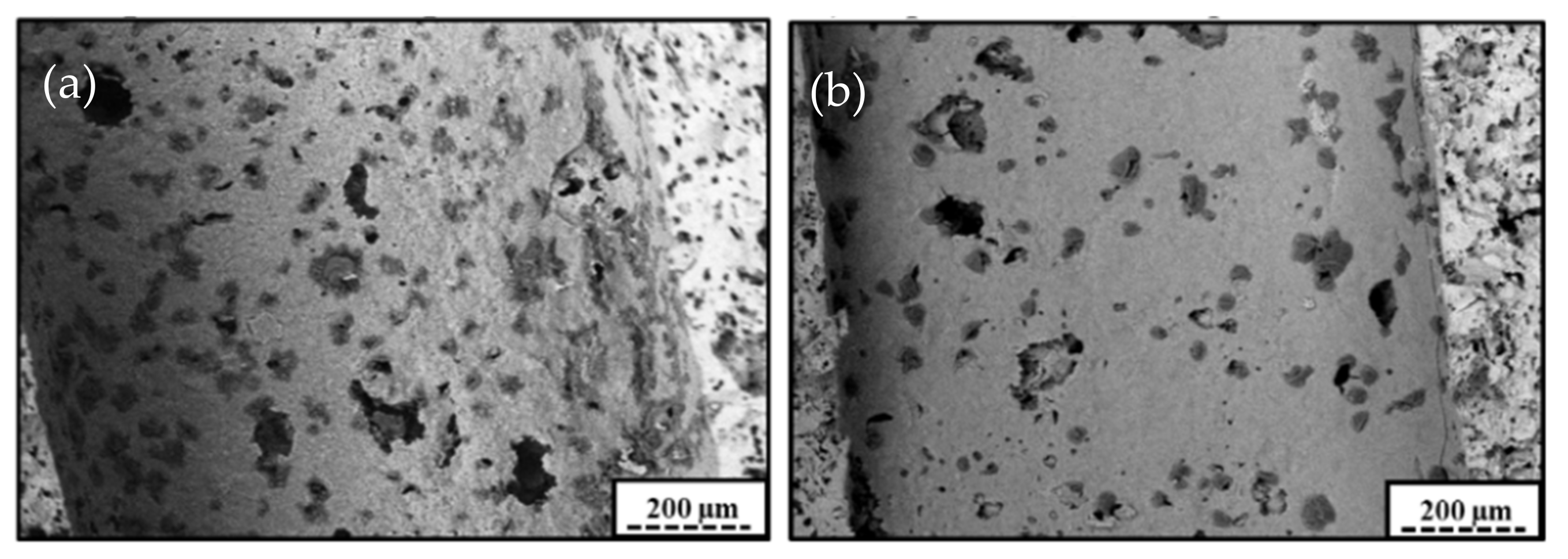
The support impregnated with a mixture of sol and slurry (sample H) presented a composite-like aspect with a homogeneous distribution of the slurry grains dispersed within the gelated sol matrix (Figure 16).
The coating of sample H presented almost no cracks, and where cracks were observed, they had smaller lengths compared to those observed in a standard sample. This beneficial association of the colloidal boehmite and the slurry of alumina particles (whose diameters are <5 µm) was also evidenced by Agrafiotis & Tsetsekou [11]. In the present case, it was assumed that the interactions at the interface between the slurry particles and the gelating sol helped the coating to resist the capillary pressure-induced shrinkage and resultant stresses during drying. Furthermore, it is assumed that the presence of slurry grains slowed down the propagation of cracks, as the energy would dissipate by the change of directions needed to bypass the slurry grains [43].
4. Conclusions
This study set the basis for the development of an efficient method for the washcoating of cordierite monolith with an aqueous sol of Ni/boehmite. Thirteen samples were coated with varying solution properties and coating procedure parameters.
The presence of high-mass losses of coating for almost all the samples was the first technical problem. From visual observations, and since the sample prepared by an individual filling of the channels with a syringe did not present this mass loss, it was deduced that the mass losses resulted from an imperfect penetration of the sols through the channels of the support. A small pressurization or depressurization applied on the solution during the coating step could be a simple and efficient way to favor the penetration of the solutions through the support channels.
Furthermore, it appears necessary to improve the coating assembly prototype in order to apply a blowdown step with an adjustable flowrate. Indeed, the sample prepared with a manual blowdown presented a good quality of coating (no cracks, no aggregates), but the too high nitrogen flux caused a high-mass loss and coating-free areas.
No influences on the coatings quality were observed at different withdrawal speed, with different solvents (water, ethanol or acetone), with a second impregnation or by filling of the channels by a syringe.
The pH of the sol appeared to play a role even more important than the viscosity. Indeed, despite having the highest viscosity, the sol acidified with nitric acid showed a coating which was almost free of cracks or of large aggregates. This was attributed to the presence of strong repulsions between positively charged boehmite particles at a strongly acidic pH, which permit the retention of a good dispersion of the particles and the prevention of aggregation of the coating in large aggregates. One direction of investigation would, therefore, be to determine the optimal pH for the deposition of the coating.
The presence of a slurry mix of calcined alumina particles and of colloidal boehmite appeared also to be an interesting path to follow. The beneficial influence of a slurry was attributed to a better resistance of the coating against the stresses induced during drying, and a deviation of the cracks in the gels by slurry grains. It would be however interesting to determine the influence of the slurry/boehmite ratio on the property of the coating.
Supplementary Materials
The following supporting information can be downloaded at: https://0-www-mdpi-com.brum.beds.ac.uk/article/10.3390/pr10050875/s1, Figure S1: Cordierite monolith nitrogen adsorption–desorption isotherms; Figure S2: Cordierite channel surface (front view) obtained with SEM–BSE at 100× magnification; Figure S3: Mercury porosimetry curve for the cordierite sample; (1) mercury volume introduced as a function of the pressure, (2) macropore size distribution.
Author Contributions
Conceptualization, Methodology, V.C., T.L. and J.G., Investigation, Formal analysis, Writing—original draft, V.C. and J.G.M., Supervision, Funding acquisition, Project administration, S.D.L. All the authors corrected the paper before submission and during the revision process. All authors have read and agreed to the published version of the manuscript.
Funding
This research received no external funding.
Institutional Review Board Statement
Not applicable.
Informed Consent Statement
Not applicable.
Data Availability Statement
The raw/processed data required to reproduce these findings cannot be shared at this time as these data are part of an ongoing study.
Acknowledgments
V.C., J.G.M. and S.D.L. thank the Belgian National Funds for Scientific Research (F.R.S.-FNRS) for his doctoral grant obtained with the “Fonds de Recherche collective” n◦ 2.4541.12., his postdoctoral fellowship and for her senior associate researcher position, respectively.
Conflicts of Interest
The authors declare no conflict of interest.
References
- Govender, S.; Friedrich, H.B. Monoliths: A Review of the Basics, Preparation Methods and Their Relevance to Oxidation. Catalysts 2017, 7, 62. [Google Scholar] [CrossRef]
- Cybulsky, A.; Moulijn, J.A. Structured Catalysts and Reactors, 2nd ed.; CRC Press: Boca Raton, FL, USA, 2006. [Google Scholar]
- Kapteijn, F.; Nijhuis, T.A.; Heiszwolf, J.J.; Moulijn, J.A. New Non-Traditional Multiphase Catalytic Reactors Based on Monolithic Structures. Catal. Today 2001, 66, 133–144. [Google Scholar] [CrossRef]
- Nijhuis, T.A.; Beers, A.E.W.; Vergunst, T.; Hoek, I.; Kapteijn, F.; Moulijn, J. Preparation of Monolithic Catalysts. Catal. Rev. 2001, 43, 345–380. [Google Scholar] [CrossRef]
- Bustinza, A.; Frías, M.; Liu, Y.; García-Bordejé, E. Mono- and Bimetallic Metal Catalysts Based on Ni and Ru Supported on Alumina-Coated Monoliths for CO2 methanation. Catal. Sci. Technol. 2020, 10, 4061–4071. [Google Scholar] [CrossRef]
- Agueniou, F.; Vidal, H.; de Dios López, J.; Hernández-Garrido, J.C.; Cauqui, M.A.; Botana, F.J.; Calvino, J.J.; Galvita, V.V.; Gatica, J.M. 3D-Printing of Metallic Honeycomb Monoliths as a Doorway to a New Generation of Catalytic Devices: The Ni-Based Catalysts in Methane Dry Reforming Showcase. Catal. Commun. 2021, 148, 106181. [Google Scholar] [CrossRef]
- Martinez, A.A.; Fixman, E.M.; Cánepa, A.L.; Barbero, B.P. Preparation, Characterization, and Application of Nano-FeOx/Al2O3/Cordierite Monolithic Catalysts for Heterogeneous Dark Fenton Reaction. J. Chem. Technol. Biotechnol. 2020, 95, 2868–2878. [Google Scholar] [CrossRef]
- Avila, P.; Montes, M.; Miró, E.E. Monolithic Reactors for Environmental Applications: A Review on Preparation Technologies. Chem. Eng. J. 2005, 109, 11–36. [Google Scholar] [CrossRef]
- Hazlett, M.J.; Epling, W.S. Heterogeneous Catalyst Design: Zoned and Layered Catalysts in Diesel Vehicle Aftertreatment Monolith Reactors. Can. J. Chem. Eng. 2019, 97, 188–206. [Google Scholar] [CrossRef]
- Elmer, H. Application of Refractories; John Wiley & Sons: Hoboken, NJ, USA, 1986. [Google Scholar]
- Agrafiotis, C.; Tsetsekou, A. Deposition of Meso-Porous y-Alumina Coatings on Ceramic Honeycombs by Sol-Gel Methods. J. Eur. Ceram. Soc. 2002, 22, 423–434. [Google Scholar] [CrossRef]
- Cybulski, A.; Moulijn, J.A. Monoliths in Heterogeneous Catalysis. Catal. Rev. Sci. Eng. 1994, 36, 179–270. [Google Scholar] [CrossRef]
- el Assal, Z.; Ojala, S.; Drif, A.; Zbair, M.; Bensitel, M.; Pirault-Roy, L.; Nevanperä, T.; Pitkäaho, S.; Keiski, R.L.; Brahmi, R. Total Oxidation of Dichloromethane over Silica Modified Alumina Catalysts Washcoated on Ceramic Monoliths. Catalysts 2018, 8, 339. [Google Scholar] [CrossRef] [Green Version]
- Vo, N.Q.D.; Huynh, N.D.T.; Huynh, H.T.; Ngo, T.H.; Hoang Luan, V.; Thi Ngoc Suong, H.; Nguyen, V.H.; Le, M.V. TiO2-SiO2 Coatings onto Cordierite Honeycomb Monolith Support for Effective Photocatalytic Degradation of β-Naphthol in a Water Solution. Mater. Lett. 2021, 302, 130461. [Google Scholar] [CrossRef]
- Peroni, B.; Navas, M.; Bideberripe, H.P.; Barbero, B.; Casella, M.L.; Jaworski, M.A. Development of PdCu Structured Catalysts Based on ZrO2-CeO2 Materials Supported on Cordierite Monoliths for Water Remediation: Removal of Hazardous Oxyanions. Ind. Eng. Chem. Res. 2021, 60, 12767–12775. [Google Scholar] [CrossRef]
- Nguyen, V.T.; Yoon, K.H.; Mok, Y.S.; Nguyen, D.B.; Dinh, D.K.; Hossain, M.M.; Saud, S.; Kim, S.J.; Kim, Y.J.; Lee, J.H.; et al. Practical-Scale Honeycomb Catalytic Reactor Coupled with Non-Thermal Plasma for High-Throughput Removal of Isopropanol. Chem. Eng. J. 2022, 430, 132905. [Google Scholar] [CrossRef]
- Sedjame, H.J.; Brahmi, R.; Lafaye, G.; Barbier, J.; Fontaine, C. Influence de La Composition Des Catalyseurs Déposés Sur Des Monolithes En Cordiérite Pour l’oxydation de l’acide Acétique. C. R. Chim. 2018, 21, 182–193. [Google Scholar] [CrossRef]
- Claude, V.; Mahy, J.G.; Geens, J.; Lambert, S.D. Ni-Doped γ-Al2O3 as Secondary Catalyst for Bio-Syngas Purification: Influence of Ni Loading, Catalyst Preparation, and Gas Composition on Catalytic Activity. Mater. Today Chem. 2019, 13, 98–109. [Google Scholar] [CrossRef]
- Claude, V.; Mahy, J.G.; Douven, S.; Pirard, S.L.; Courson, C.; Lambert, S.D. Ni- and Fe-Doped g-Al2O3 or Olivine as Primary Catalyst for Toluene Reforming. Mater. Today Chem. 2019, 14, 100197. [Google Scholar] [CrossRef]
- Xu, L.; Song, H.; Chou, L. Ordered Mesoporous MgO–Al2O3 Composite Oxides Supported Ni Based Catalysts for CO2 Reforming of CH4: Effects of Basic Modifier and Mesopore Structure. Int. J. Hydrogen Energy 2013, 38, 7307–7325. [Google Scholar] [CrossRef]
- Świerczyński, D.; Libs, S.; Courson, C.; Kiennemann, a. Steam Reforming of Tar from a Biomass Gasification Process over Ni/Olivine Catalyst Using Toluene as a Model Compound. Appl. Catal. B Environ. 2007, 74, 211–222. [Google Scholar] [CrossRef]
- Mahy, J.G.; Claude, V.; Sacco, L.; Lambert, S.D. Ethylene Polymerization and Hydrodechlorination of 1,2-Dichloroethane Mediated by Nickel(II) Covalently Anchored to Silica Xerogels. J. Sol-Gel Sci. Technol. 2017, 81, 59–68. [Google Scholar] [CrossRef]
- Taylor, G.I. Deposition of a Viscous Fluid on a Plane Surface. J. Fluid Mech. 1961, 9, 218. [Google Scholar] [CrossRef]
- Fairbrother, F.; Stubbs, A.E. Studies in Electro-Endosmosis. Part VI. The “Bubble-Tube” Method of Measurement. J. Chem. Soc. (Resumed) 1935, 527–529. [Google Scholar] [CrossRef]
- Kolb, W.B.; Cerro, R.L. Coating the inside of a Capillary of Square Cross Section. Chem. Eng. Sci. 1991, 46, 2181–2195. [Google Scholar] [CrossRef]
- Kolb, W.B.; Papadimitriou, A.A.; Cerro, R.L.; Leavitt, D.D.; Summers, J.C. Ins and Outs of Coating Monolithic Structures. Chem. Eng. Prog. 1993, 89, 61–67. [Google Scholar]
- Agrafiotis, C.; Tsetsekou, A.; Ekonomakou, A. Effect of Particle Size on the Adhesion Properties of Oxide Washcoats on Cordierite Honeycombs. J. Mater. Sci. Lett. 1999, 18, 1421–1424. [Google Scholar] [CrossRef]
- Claude, V.; Courson, C.; Köhler, M.; Lambert, S.D. Overview and Essentials of Biomass Gasification Technologies and Their Catalytic Cleaning Methods. Energy Fuels 2016, 30, 8791–8814. [Google Scholar] [CrossRef]
- Lecloux, J. Texture of Catalysts. Catal. Sci. Technol. 1981, 2, 171. [Google Scholar]
- Bodson, C.J.; Heinrichs, B.; Tasseroul, L.; Bied, C.; Mahy, J.G.; Wong Chi Man, M.; Lambert, S.D. Efficient P- and Ag-Doped Titania for the Photocatalytic Degradation of Waste Water Organic Pollutants. J. Alloys Compd. 2016, 682, 144–153. [Google Scholar] [CrossRef]
- Mueller, S.; Lllewellin, E.; Mader, H. The Rheology of Suspensions of Solid Particles. Proc. R. Soc. 2010, 466, 1201–1228. [Google Scholar] [CrossRef] [Green Version]
- Rector, D.; Bunker, B. Effect of Collooidal Aggregation on the Sedimentation and Rheological Properties of Tank Waste; Pacific Northwest National Laboratory (PNNL): Richland, WA, USA, 1995.
- Agrafiotis, C.; Tsetsekou, A. The Effect of Powder Characteristics on Washcoat Quality. Part I: Alumina Washcoats. J. Eur. Ceram. Soc. 2000, 20, 815–824. [Google Scholar] [CrossRef]
- Ananthakumar, S.; Raja, V.; Warrier, K.G.K. Effect of Nanoparticulate Boehmite Sol as a Dispersant for Slurry Compaction of Alumina Ceramics. Mater. Lett. 2000, 43, 174–179. [Google Scholar] [CrossRef]
- Constantes Dieletriques and Absolute Viscosity. Available online: http://www.ddbst.com/ (accessed on 17 February 2022).
- Troy, D.; Beringer, P. The Science and Practice of Pharmacy; Lippincott Williams & Wilkins: Philadelphia, PA, USA, 2006. [Google Scholar]
- Lange, N.A.; Dean, J.A. Lange’s Handbook of Chemistry, 10th ed.; McGraw-Hill: New York, NY, USA, 1967; ISBN 0070161909. [Google Scholar]
- Raybaud, P.; Digne, M.; Sautet, P.; Euzen, P.; Toulhoat, H. Use of DFT to Achieve a Rational Understanding of Acid-Basic Properties of Gamma-Alumina Surfaces. J. Catal. 2004, 226, 54–68. [Google Scholar] [CrossRef]
- Alphonse, P.; Courty, M. Structure and Thermal Behavior of Nanocrystalline Boehmite. Thermochim. Acta 2005, 425, 75–89. [Google Scholar] [CrossRef] [Green Version]
- Hayes, R.E.; Liu, B.; Moxom, R.; Votsmeier, M. The Effect of Washcoat Geometry on Mass Transfer in Monolith Reactors. Chem. Eng. Sci. 2004, 59, 3169–3181. [Google Scholar] [CrossRef]
- Leenaars, A.F.M.; Burggraaf, A.J. The Preparation and Characterization of Alumina Membranes with Ultra-Fine Pores. J. Membr. Sci. 1985, 24, 261–270. [Google Scholar] [CrossRef] [Green Version]
- Brinker, C.; Scherer, G. Sol-Gel Science: The Physics and Chemistry of Sol-Gel Processing; Academic Press: San Diego, CA, USA, 1990; ISBN 9780121349707. [Google Scholar]
- Rice, R. Mechanical Properties of Ceramics and Composites: Grain and Particle Effects; CRC Press: Boca Raton, FL, USA, 2000; ISBN 0824745280. [Google Scholar]
Figure 1.
Types of monoliths as a function of the method of deposition of the active phase and of the porous properties of the monolith constitutive material. (a) integral (b) high-surface (c) low-surface.
Figure 1.
Types of monoliths as a function of the method of deposition of the active phase and of the porous properties of the monolith constitutive material. (a) integral (b) high-surface (c) low-surface.

Figure 2.
Coating process used by Kolb [26].
Figure 2.
Coating process used by Kolb [26].

Figure 3.
Cordierite monolith used in this work.

Figure 4.
Coating apparatus used for the coating of cordierite supports with Ni/boehmite gels.

Figure 5.
Particle size distribution of a standard Ni/boehmite sol (sample A).

Figure 6.
PZC measurements performed on cordierite and the standard Ni/boehmite sol (sample A).

Figure 7.
Viscosity of the coating solutions at 10, 20, 50 and 100 rpm.

Figure 8.
Particle size distribution of Ni/γ-Al2O3 slurry sol (sample G).

Figure 9.
General evolutions of the viscosity of boehmite sols versus pH for different loadings of solid [32].
Figure 9.
General evolutions of the viscosity of boehmite sols versus pH for different loadings of solid [32].

Figure 10.
Schematic representation of a channel and monolith section seen from the top.

Figure 11.
Diagram showing the actual load of coating compared to the theoretical load of coating. The error intervals were estimated by taking into account the uncertainty about the monolith diameters.
Figure 11.
Diagram showing the actual load of coating compared to the theoretical load of coating. The error intervals were estimated by taking into account the uncertainty about the monolith diameters.

Figure 12.
Picture of sample G: (a) magnification of 100×, (b) magnification of 1000×.

Figure 13.
Illustrations of the three main type coating-free areas encountered.

Figure 14.
Homogeneous coatings with presence of dark spots: (a) sample A-blown, (b) sample D.

Figure 15.
Influence of the coating thickness on the appearance of cracks for sample B after drying step; (a) thickness below the critical value, (b) thickness above the critical value.
Figure 15.
Influence of the coating thickness on the appearance of cracks for sample B after drying step; (a) thickness below the critical value, (b) thickness above the critical value.

Figure 16.
Pictures of dried coatings; (a) sample H, (b) cracks on sample H coating, (c) cracks on sample A coating.
Figure 16.
Pictures of dried coatings; (a) sample H, (b) cracks on sample H coating, (c) cracks on sample A coating.


Table 1.
Modifications to the coating solutions and corresponding viscosity.
| Samples | Type of Suspension | Modified Parameter | Coating Solution Viscosity (in cP—At 10 rpm and 25 °C) |
|---|---|---|---|
| A | Precursor (Ni/boehmite) | - | 630 |
| B | Precursor (Ni/boehmite) | Solution concentration divided per 2 (25 g/L) | 80 |
| C | Precursor (Ni/boehmite) | Solution concentration doubled (100 g/L) | (too high to be measured) |
| D | Precursor (Ni/boehmite) | Solution pH (1.8) | 1490 |
| E | Precursor (Ni/boehmite) | Solution solvent (acetone) | 710 |
| F | Precursor (Ni/boehmite) | Solution solvent (ethanol) | 1100 |
| G | Pre-calcined Ni/Al2O3 nanoparticles | Coating with a slurry composed of calcined Ni/γ-Al2O3, crushed below 45 µm and dispersed in water. | ~1 |
| H | Pre-calcined Ni/Al2O3 nanoparticles | Suspension A/H 50/50% vol. mixture | 200 |
Table 2.
Modifications of the coating procedures for sample A.
| Samples | Modified Parameter |
|---|---|
| A | - |
| A-0.5V | Withdrawal speed (×0.5) |
| A-2V | Withdrawal speed (×2) |
| 2A | Number of impregnations (2) |
| A-syringe | Channels filled with a syringe |
| A-blow | Blowdown step |
Table 3.
Coated samples, related coating method and observed defects on dried coatings.
| Samples | Modified Parameters | Coating Solution Viscosity at 10 rpm (cP) | Coating-Free Areas | Cracks | Aggregates |
|---|---|---|---|---|---|
| A | - | 630 | Yes | Yes | Yes |
| A-0.5V | Withdrawal speed (×0.5) | 630 | Yes | Yes | Yes |
| A-2V | Withdrawal speed (×2) | 630 | Yes | Yes | Yes |
| B | Solution concentration (×0.5) | 80 | Little | Almost none | Few |
| C | Solution concentration (×2) | Impregnation not possible, solution too much viscous | |||
| D | Solution pH (1.8) | 1490 | Little | Almost none | Few |
| E | Solution solvent (acetone) | 710 | Yes | Yes | Yes |
| F | Solution solvent (ethanol) | 1100 | Yes | Yes | Yes |
| 2A | Number of impregnations (×2) | 630 | Yes | Yes | Yes |
| A-syringe | Channels filled with a syringe | 630 | Yes | Yes | Yes |
| A-blow | Blowdown step | 630 | Yes | No | No |
| H | Particles slurry instead of boehmite sol | ~1 | Almost exclusively (scattered particles) | No | No |
| G | Slurry/sol 50/50% vol. mixture | 200 | Almost none | Little | Few |
Publisher’s Note: MDPI stays neutral with regard to jurisdictional claims in published maps and institutional affiliations. |
© 2022 by the authors. Licensee MDPI, Basel, Switzerland. This article is an open access article distributed under the terms and conditions of the Creative Commons Attribution (CC BY) license (https://creativecommons.org/licenses/by/4.0/).
Share and Cite
MDPI and ACS Style
Claude, V.; Mahy, J.G.; Lohay, T.; Geens, J.; Lambert, S.D. Coating Process of Honeycomb Cordierite Support with Ni/Boehmite Gels. Processes 2022, 10, 875. https://0-doi-org.brum.beds.ac.uk/10.3390/pr10050875
AMA Style
Claude V, Mahy JG, Lohay T, Geens J, Lambert SD. Coating Process of Honeycomb Cordierite Support with Ni/Boehmite Gels. Processes. 2022; 10(5):875. https://0-doi-org.brum.beds.ac.uk/10.3390/pr10050875
Chicago/Turabian StyleClaude, Vincent, Julien G. Mahy, Timothée Lohay, Jérémy Geens, and Stéphanie D. Lambert. 2022. "Coating Process of Honeycomb Cordierite Support with Ni/Boehmite Gels" Processes 10, no. 5: 875. https://0-doi-org.brum.beds.ac.uk/10.3390/pr10050875
Note that from the first issue of 2016, this journal uses article numbers instead of page numbers. See further details here.